EL- NISSAN ALMERA N16 2003 Electronic Repair Manual
[x] Cancel search | Manufacturer: NISSAN, Model Year: 2003, Model line: ALMERA N16, Model: NISSAN ALMERA N16 2003Pages: 3189, PDF Size: 54.76 MB
Page 16 of 3189
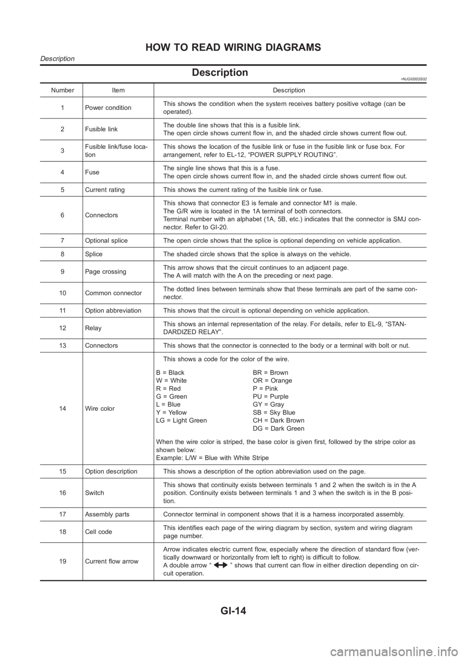
Description=NJGI0003S02
Number Item Description
1 Power conditionThis shows the condition when the system receives battery positive voltage (can be
operated).
2 Fusible linkThe double line shows that this is a fusible link.
The open circle shows current flow in, and the shaded circle shows current flow out.
3Fusible link/fuse loca-
tionThis shows the location of the fusible link or fuse in the fusible link or fusebox.For
arrangement, refer to EL-12, “POWER SUPPLY ROUTING”.
4FuseThe single line shows that this is a fuse.
The open circle shows current flow in, and the shaded circle shows current flow out.
5 Current rating This shows the current rating of the fusible link or fuse.
6 ConnectorsThis shows that connector E3 is female and connector M1 is male.
The G/R wire is located in the 1A terminal of both connectors.
Terminal number with an alphabet (1A, 5B, etc.) indicates that the connector is SMJ con-
nector. Refer to GI-20.
7 Optional splice The open circle shows that the splice is optional depending on vehicle application.
8 Splice The shaded circle shows that the splice is always on the vehicle.
9 Page crossingThis arrow shows that the circuit continues to an adjacent page.
The A will match with the A on the preceding or next page.
10 Common connectorThe dotted lines between terminals show that these terminals are part of thesamecon-
nector.
11 Option abbreviation This shows that the circuit is optional depending on vehicle application.
12 RelayThis shows an internal representation of the relay. For details, refer to EL-9, “STAN-
DARDIZED RELAY”.
13 Connectors This shows that the connector is connected to the body or a terminal with bolt or nut.
14 Wire colorThis shows a code for the color of the wire.
B=Black
W = White
R = Red
G = Green
L = Blue
Y = Yellow
LG = Light GreenBR = Brown
OR = Orange
P = Pink
PU = Purple
GY = Gray
SB = Sky Blue
CH = Dark Brown
DG=DarkGreen
When the wire color is striped, the base color is given first, followed by the stripe color as
shown below:
Example: L/W = Blue with White Stripe
15 Option description This shows a description of the option abbreviationused on the page.
16 SwitchThis shows that continuity exists between terminals 1 and 2 when the switchis in the A
position. Continuity exists between terminals 1 and 3 when the switch is inthe B posi-
tion.
17 Assembly parts Connector terminal in component shows that it is a harness incorporated assembly.
18 Cell codeThis identifies each page of the wiring diagram by section, system and wiring diagram
page number.
19 Current flow arrowArrow indicates electric current flow, especially where the direction ofstandard flow (ver-
tically downward or horizontally from left to right) is difficult to follow.
A double arrow “
” shows that current can flow in either direction depending on cir-
cuit operation.
HOW TO READ WIRING DIAGRAMS
Description
GI-14
Page 17 of 3189
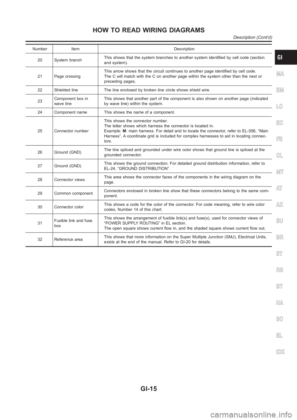
Number Item Description
20 System branchThis shows that the system branches to another system identified by cell code (section
and system).
21 Page crossingThis arrow shows that the circuit continues to another page identified by cell code.
The C will match with the C on another page within the system other than the next or
preceding pages.
22 Shielded line The line enclosed by broken line circle shows shield wire.
23Component box in
wave lineThis shows that another part of the component is also shown on another page (indicated
by wave line) within the system.
24 Component name This shows the name of a component.
25 Connector numberThis shows the connector number.
The letter shows which harness the connector is located in.
Example:M: main harness. For detail and to locate the connector, refer to EL-556, “Main
Harness”. A coordinate grid is included for complex harnesses to aid in locating connec-
tors.
26 Ground (GND)The line spliced and grounded under wire color shows that ground line is spliced at the
grounded connector.
27 Ground (GND)This shows the ground connection. For detailed ground distribution information, refer to
EL-24, “GROUND DISTRIBUTION”.
28 Connector viewsThis area shows the connector faces of the components in the wiring diagramon the
page.
29 Common componentConnectors enclosed in broken line show that these connectors belong to thesamecom-
ponent.
30 Connector colorThis shows a code for the color of the connector. For code meaning, refer to wire color
codes, Number 14 of this chart.
31Fusible link and fuse
boxThis shows the arrangement of fusible link(s) and fuse(s), used for connector views of
“POWER SUPPLY ROUTING” in EL section.
The open square shows current flow in, and the shaded square shows current flow out.
32 Reference areaThis shows that more information on the Super Multiple Junction (SMJ), Electrical Units,
exists at the end of the manual. Refer to GI-20 for details.
MA
EM
LC
EC
FE
CL
MT
AT
AX
SU
BR
ST
RS
BT
HA
SC
EL
IDX
HOW TO READ WIRING DIAGRAMS
Description (Cont’d)
GI-15
Page 18 of 3189
SGI364
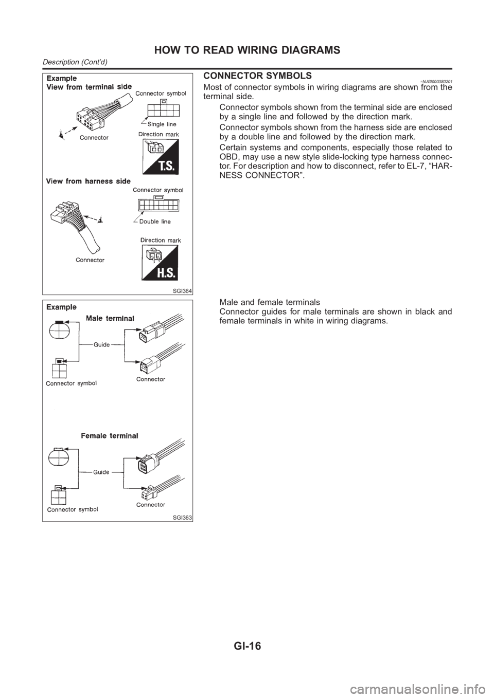
CONNECTOR SYMBOLS=NJGI0003S0201Most of connector symbols in wiring diagrams are shown from the
terminal side.
Connector symbols shown from the terminal side are enclosed
by a single line and followed by the direction mark.
Connector symbols shown from the harness side are enclosed
by a double line and followed by the direction mark.
Certain systems and components, especially those related to
OBD, may use a new style slide-locking type harness connec-
tor. For description and how to disconnect, refer to EL-7, “HAR-
NESS CONNECTOR”.
SGI363
Male and female terminals
Connector guides for male terminals are shown in black and
female terminals in white in wiring diagrams.
HOW TO READ WIRING DIAGRAMS
Description (Cont’d)
GI-16
Page 64 of 3189
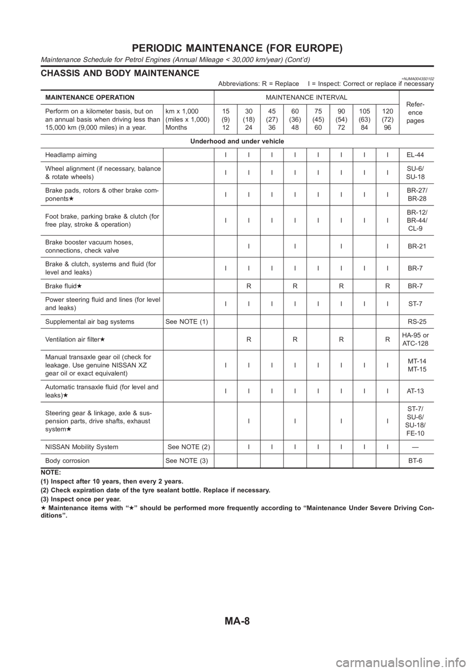
CHASSIS AND BODY MAINTENANCE=NJMA0043S0102Abbreviations: R = Replace I = Inspect: Correct or replace if necessary
MAINTENANCE OPERATIONMAINTENANCE INTERVAL
Refer-
ence
pages Perform on a kilometer basis, but on
an annual basis when driving less than
15,000 km (9,000 miles) in a year.kmx1,000
(miles x 1,000)
Months15
(9)
1230
(18)
2445
(27)
3660
(36)
4875
(45)
6090
(54)
72105
(63)
84120
(72)
96
Underhood and under vehicle
Headlamp aimingIIIIIIIIEL-44
Wheel alignment (if necessary, balance
& rotate wheels)IIIIIIIISU-6/
SU-18
Brake pads, rotors & other brake com-
ponents★IIIIIIIIBR-27/
BR-28
Foot brake, parking brake & clutch (for
free play, stroke & operation)IIIIIIIIBR-12/
BR-44/
CL-9
Brake booster vacuum hoses,
connections, check valveIIIIBR-21
Brake & clutch, systems and fluid (for
level and leaks)IIIIIIIIBR-7
Brake fluid★RRRRBR-7
Power steering fluid and lines (for level
and leaks)IIIIIIIIST-7
Supplemental air bag systems See NOTE (1) RS-25
Ventilation air filter★RRRRHA-95 or
AT C - 1 2 8
Manual transaxle gear oil (check for
leakage. Use genuine NISSAN XZ
gear oil or exact equivalent)IIIIIIIIMT-14
MT-15
Automatic transaxle fluid (for level and
leaks)★IIIIIIIIAT-13
Steering gear & linkage, axle & sus-
pension parts, drive shafts, exhaust
system★IIIIST-7/
SU-6/
SU-18/
FE-10
NISSAN Mobility System See NOTE (2)IIIIIII —
Body corrosion See NOTE (3) BT-6
NOTE:
(1) Inspect after 10 years, then every 2 years.
(2) Check expiration date of the tyre sealant bottle. Replace if necessary.
(3) Inspect once per year.
★Maintenance items with “★” should be performed more frequently according to “Maintenance Under Severe Driving Con-
ditions”.
PERIODIC MAINTENANCE (FOR EUROPE)
Maintenance Schedule for Petrol Engines (Annual Mileage < 30,000 km/year) (Cont’d)
MA-8
Page 66 of 3189
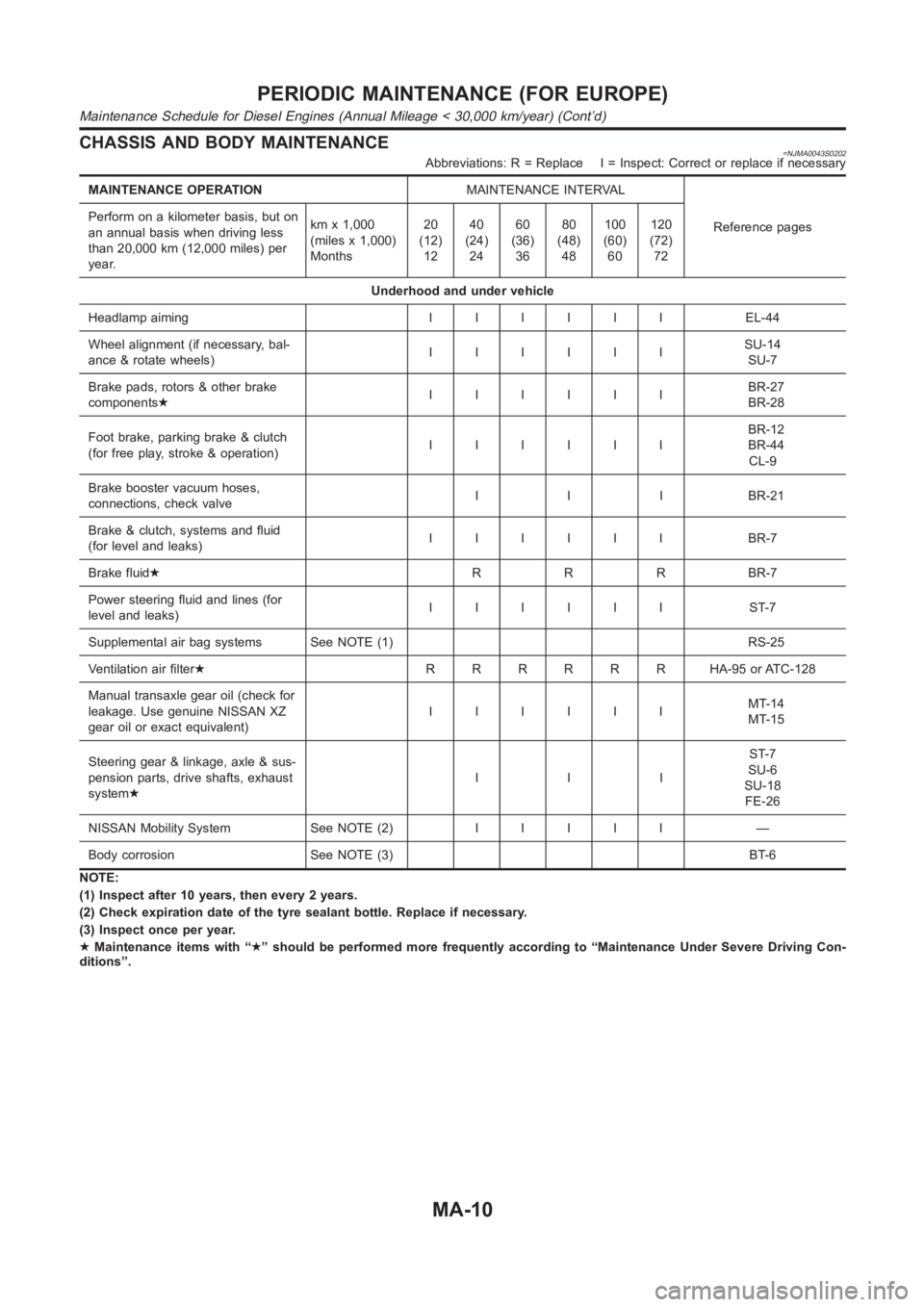
CHASSIS AND BODY MAINTENANCE=NJMA0043S0202Abbreviations: R = Replace I = Inspect: Correct or replace if necessary
MAINTENANCE OPERATIONMAINTENANCE INTERVAL
Reference pages Perform on a kilometer basis, but on
an annual basis when driving less
than 20,000 km (12,000 miles) per
year.kmx1,000
(miles x 1,000)
Months20
(12)
1240
(24)
2460
(36)
3680
(48)
48100
(60)
60120
(72)
72
Underhood and under vehicle
Headlamp aimingIIIIII EL-44
Wheel alignment (if necessary, bal-
ance & rotate wheels)IIIIIISU-14
SU-7
Brake pads, rotors & other brake
components★IIIIIIBR-27
BR-28
Foot brake, parking brake & clutch
(for free play, stroke & operation)IIIIIIBR-12
BR-44
CL-9
Brake booster vacuum hoses,
connections, check valveI I I BR-21
Brake & clutch, systems and fluid
(for level and leaks)IIIIII BR-7
Brake fluid★R R R BR-7
Power steering fluid and lines (for
level and leaks)IIIIII ST-7
Supplemental air bag systems See NOTE (1) RS-25
Ventilation air filter★RRRRRR HA-95orATC-128
Manual transaxle gear oil (check for
leakage. Use genuine NISSAN XZ
gear oil or exact equivalent)IIIIIIMT-14
MT-15
Steering gear & linkage, axle & sus-
pension parts, drive shafts, exhaust
system★IIIST-7
SU-6
SU-18
FE-26
NISSAN Mobility System See NOTE (2)IIIII —
Body corrosion See NOTE (3) BT-6
NOTE:
(1) Inspect after 10 years, then every 2 years.
(2) Check expiration date of the tyre sealant bottle. Replace if necessary.
(3) Inspect once per year.
★Maintenance items with “★” should be performed more frequently according to “Maintenance Under Severe Driving Con-
ditions”.
PERIODIC MAINTENANCE (FOR EUROPE)
Maintenance Schedule for Diesel Engines (Annual Mileage < 30,000 km/year) (Cont’d)
MA-10
Page 70 of 3189
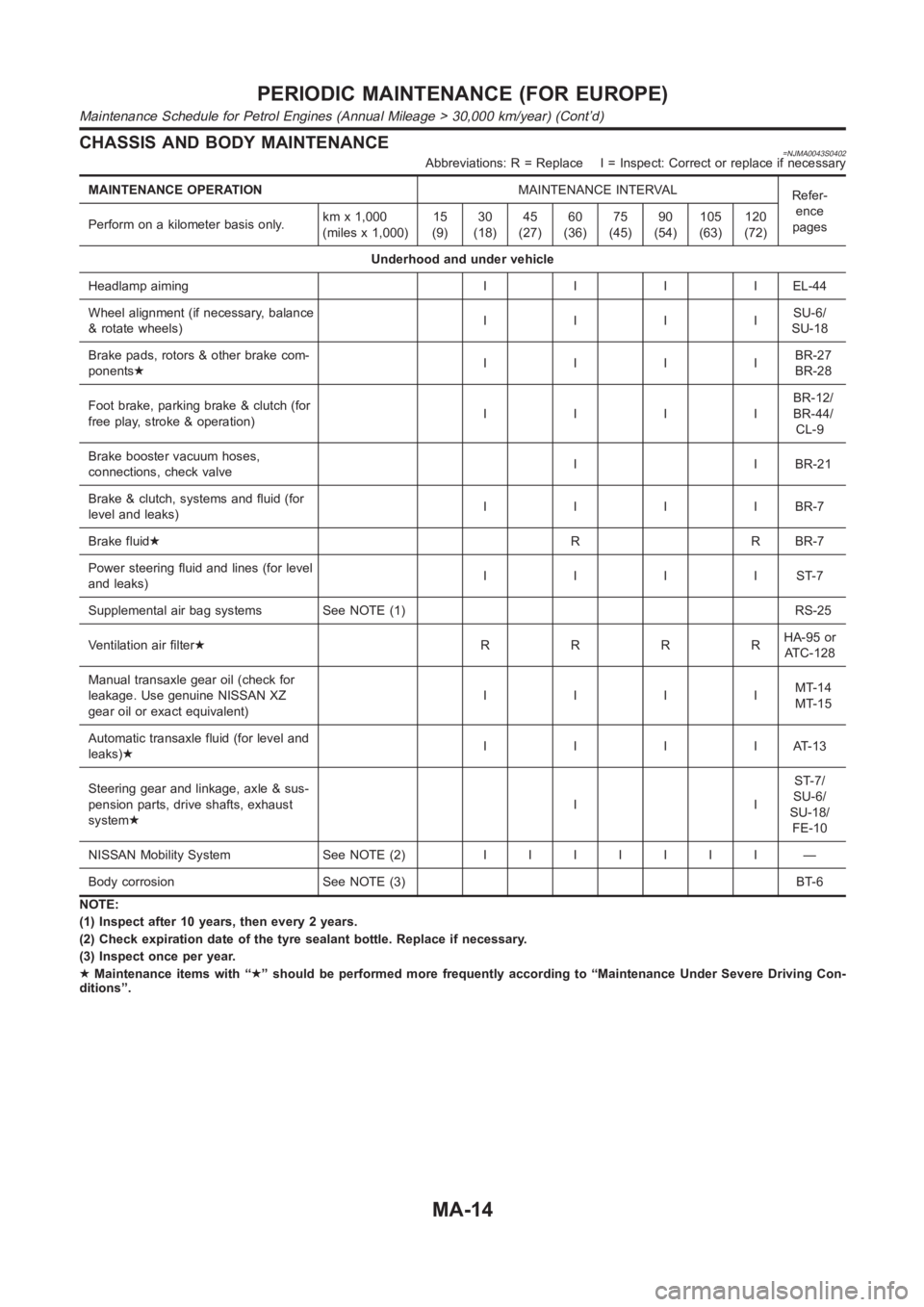
CHASSIS AND BODY MAINTENANCE=NJMA0043S0402Abbreviations: R = Replace I = Inspect: Correct or replace if necessary
MAINTENANCE OPERATIONMAINTENANCE INTERVAL
Refer-
ence
pages Perform on a kilometer basis only.kmx1,000
(miles x 1,000)15
(9)30
(18)45
(27)60
(36)75
(45)90
(54)105
(63)120
(72)
Underhood and under vehicle
Headlamp aimingIIIIEL-44
Wheel alignment (if necessary, balance
& rotate wheels)IIIISU-6/
SU-18
Brake pads, rotors & other brake com-
ponents★IIIIBR-27
BR-28
Foot brake, parking brake & clutch (for
free play, stroke & operation)IIIIBR-12/
BR-44/
CL-9
Brake booster vacuum hoses,
connections, check valveI I BR-21
Brake & clutch, systems and fluid (for
level and leaks)IIIIBR-7
Brake fluid★R R BR-7
Power steering fluid and lines (for level
and leaks)IIIIST-7
Supplemental air bag systems See NOTE (1) RS-25
Ventilation air filter★RRRRHA-95 or
AT C - 1 2 8
Manual transaxle gear oil (check for
leakage. Use genuine NISSAN XZ
gear oil or exact equivalent)IIIIMT-14
MT-15
Automatic transaxle fluid (for level and
leaks)★IIIIAT-13
Steering gear and linkage, axle & sus-
pension parts, drive shafts, exhaust
system★IIST-7/
SU-6/
SU-18/
FE-10
NISSAN Mobility System See NOTE (2)IIIIIII —
Body corrosion See NOTE (3) BT-6
NOTE:
(1) Inspect after 10 years, then every 2 years.
(2) Check expiration date of the tyre sealant bottle. Replace if necessary.
(3) Inspect once per year.
★Maintenance items with “★” should be performed more frequently according to “Maintenance Under Severe Driving Con-
ditions”.
PERIODIC MAINTENANCE (FOR EUROPE)
Maintenance Schedule for Petrol Engines (Annual Mileage > 30,000 km/year) (Cont’d)
MA-14
Page 72 of 3189
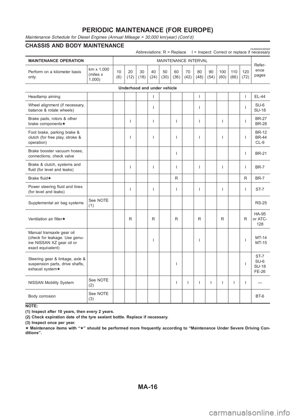
CHASSIS AND BODY MAINTENANCE=NJMA0043S0502Abbreviations: R = Replace I = Inspect: Correct or replace if necessary
MAINTENANCE OPERATIONMAINTENANCE INTERVAL
Refer-
ence
pages Perform on a kilometer basis
only.kmx1,000
(miles x
1,000)10
(6)20
(12)30
(18)40
(24)50
(30)60
(36)70
(42)80
(48)90
(54)100
(60)11 0
(66)120
(72)
Underhood and under vehicle
Headlamp aiming I I I EL-44
Wheel alignment (if necessary,
balance & rotate wheels)IIISU-6
SU-18
Brake pads, rotors & other
brake components★IIIIIIBR-27
BR-28
Foot brake, parking brake &
clutch (for free play, stroke &
operation)IIIIIIBR-12
BR-44
CL-9
Brake booster vacuum hoses,
connections, check valveI I BR-21
Brake & clutch, systems and
fluid (for level and leaks)IIIIIIBR-7
Brake fluid★R R BR-7
Power steering fluid and lines
(for level and leaks)IIIIIIST-7
Supplemental air bag systemsSee NOTE
(1)RS-25
Ventilation air filter★RRRRRRHA-95
or ATC-
128
Manual transaxle gear oil
(check for leakage. Use genu-
ine NISSAN XZ gear oil or
exact equivalent)IIIMT-14
MT-15
Steering gear & linkage, axle &
suspension parts, drive shafts,
exhaust system★IIST-7
SU-6
SU-18
FE-26
NISSAN Mobility SystemSee NOTE
(2)IIIIIII —
Body corrosionSee NOTE
(3)BT-6
NOTE:
(1) Inspect after 10 years, then every 2 years.
(2) Check expiration date of the tyre sealant bottle. Replace if necessary.
(3) Inspect once per year.
★Maintenance items with “★” should be performed more frequently according to “Maintenance Under Severe Driving Con-
ditions”.
PERIODIC MAINTENANCE (FOR EUROPE)
Maintenance Schedule for Diesel Engines (Annual Mileage > 30,000 km/year) (Cont’d)
MA-16
Page 120 of 3189
![NISSAN ALMERA N16 2003 Electronic Repair Manual EM-42
[QG]
CAMSHAFT
Valve Lifter Hole Diameter
●Using inside micrometer, measure diameter of valve lifter hole of
cylinder head.
Calculation of Valve Lifter Clearance
(Valve lifter clearance) = (hol NISSAN ALMERA N16 2003 Electronic Repair Manual EM-42
[QG]
CAMSHAFT
Valve Lifter Hole Diameter
●Using inside micrometer, measure diameter of valve lifter hole of
cylinder head.
Calculation of Valve Lifter Clearance
(Valve lifter clearance) = (hol](/img/5/57350/w960_57350-119.png)
EM-42
[QG]
CAMSHAFT
Valve Lifter Hole Diameter
●Using inside micrometer, measure diameter of valve lifter hole of
cylinder head.
Calculation of Valve Lifter Clearance
(Valve lifter clearance) = (hole diameter of valve lifter) – (outer diam-
eter of valve lifter).
●When out of specified range, referring to each specification of outer and inner diameter, replace either or
both valve lifter and cylinder head.
Valve ClearanceEBS00LQC
INSPECTION
●The following procedure is applicable when: Components related to camshafts or valves are removed,
installed, or replaced. Drivability concerns (poor starting, poor idling, noise) are caused by valve clearance
aging.
1. Warm up engine, and stop.
2. Remove RH splash cover (integrated with undercover).
3. Remove rocker cover. Refer to EM-29, "
ROCKER COVER" .
4. Turn crankshaft pulley clockwise (viewed from front) to align yel-
low paint with timing indicator.
5. At this point, confirm that both intake and exhaust cam noses on
No. 1 cylinder face outward. (No. 1 cylinder is at TDC of its com-
pression stroke.)
●If not, turn crankshaft pulley more.
NOTE:
Or, valves to be checked when No. 4 cylinder is at TDC of its
compression stroke can be checked first following step 8.
6. Referring to figure, measure valve clearances of valves with × in
table below using a thickness gauge.Standard (Intake and exhaust)
: 30.000 - 30.021 mm (1.1811 - 1.1819 in) dia.
Standard (Intake and exhaust)
: 0.025 - 0.061 mm (0.0010 - 0.0024 in)
SEM867E
MBIB0222E
Cylinder No.1 No.2 No.3 No.4
Valve INT EXH INT EXH INT EXH INT EXH
No. 1 cylinder at
TDC of its compres-
sion stroke××× ×
MBIB0223E
MBIB0224E
Page 226 of 3189
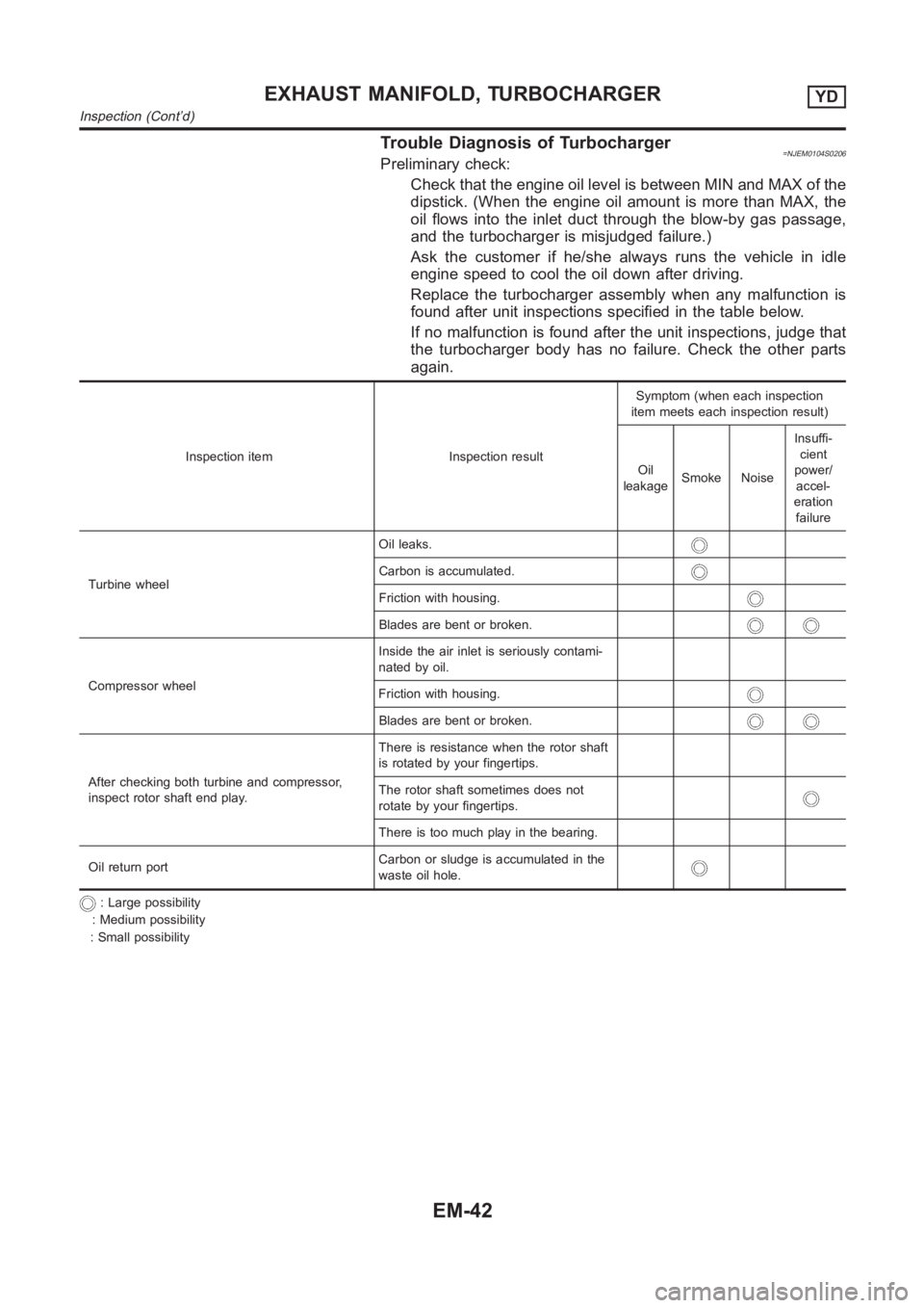
Trouble Diagnosis of Turbocharger=NJEM0104S0206Preliminary check:
Check that the engine oil level is between MIN and MAX of the
dipstick. (When the engine oil amount is more than MAX, the
oil flows into the inlet duct through the blow-by gas passage,
and the turbocharger is misjudged failure.)
Ask the customer if he/she always runs the vehicle in idle
engine speed to cool the oil down after driving.
Replace the turbocharger assembly when any malfunction is
found after unit inspections specified in the table below.
If no malfunction is found after the unit inspections, judge that
the turbocharger body has no failure. Check the other parts
again.
Inspection item Inspection resultSymptom (when each inspection
item meets each inspection result)
Oil
leakageSmoke NoiseInsuffi-
cient
power/
accel-
eration
failure
Turbine wheelOil leaks.
Carbon is accumulated.
Friction with housing.
Blades are bent or broken.
Compressor wheelInside the air inlet is seriously contami-
nated by oil.
Friction with housing.
Blades are bent or broken.
After checking both turbine and compressor,
inspect rotor shaft end play.There is resistance when the rotor shaft
is rotated by your fingertips.
The rotor shaft sometimes does not
rotate by your fingertips.
There is too much play in the bearing.
Oil return portCarbon or sludge is accumulated in the
waste oil hole.
: Large possibility
: Medium possibility
: Small possibility
EXHAUST MANIFOLD, TURBOCHARGERYD
Inspection (Cont’d)
EM-42
Page 345 of 3189
![NISSAN ALMERA N16 2003 Electronic Repair Manual PRECAUTIONS
EC-15
[QG (WITH EURO-OBD)]
C
D
E
F
G
H
I
J
K
L
MA
EC
PRECAUTIONSPFP:00001
Precautions for Supplemental Restraint System (SRS) “AIR BAG” and “SEAT
BELT PRE-TENSIONER”
EBS00K2V
The NISSAN ALMERA N16 2003 Electronic Repair Manual PRECAUTIONS
EC-15
[QG (WITH EURO-OBD)]
C
D
E
F
G
H
I
J
K
L
MA
EC
PRECAUTIONSPFP:00001
Precautions for Supplemental Restraint System (SRS) “AIR BAG” and “SEAT
BELT PRE-TENSIONER”
EBS00K2V
The](/img/5/57350/w960_57350-344.png)
PRECAUTIONS
EC-15
[QG (WITH EURO-OBD)]
C
D
E
F
G
H
I
J
K
L
MA
EC
PRECAUTIONSPFP:00001
Precautions for Supplemental Restraint System (SRS) “AIR BAG” and “SEAT
BELT PRE-TENSIONER”
EBS00K2V
The Supplemental Restraint System such as “AIR BAG” and “SEAT BELT PRE-TENSIONER”, used along
with a front seat belt, helps to reduce the risk or severity of injury to the driver and front passenger for certain
types of collision. Information necessary to service the system safely is included in the SRS and SB section of
this Service Manual.
WARNING:
●To avoid rendering the SRS inoperative, which could increase the risk of personal injury or death
in the event of a collision which would result in air bag inflation, all maintenance must be per-
formed by an authorized NISSAN/INFINITI dealer.
●Improper maintenance, including incorrect removal and installation of the SRS, can lead to per-
sonal injury caused by unintentional activation of the system. For removal of Spiral Cable and Air
Bag Module, see the SRS section.
●Do not use electrical test equipment on any circuit related to the SRS unless instructed to in this
Service Manual. SRS wiring harnesses can be identified by yellow and/or orange harness connec-
tors.
On Board Diagnostic (OBD) System of Engine and A/TEBS00K2W
The ECM has an on board diagnostic system. It will light up the malfunction indicator (MI) to warn the driver of
a malfunction causing emission deterioration.
CAUTION:
●Be sure to turn the ignition switch OFF and disconnect the battery ground cable before any repair
or inspection work. The open/short circuit of related switches, sensors, solenoid valves, etc. will
cause the MI to light up.
●Be sure to connect and lock the connectors securely after work. A loose (unlocked) connector will
cause the MI to light up due to the open circuit. (Be sure the connector is free from water, grease,
dirt, bent terminals, etc.)
●Certain systems and components, especially those related to OBD, may use a new style slide-
locking type harness connector. For description and how to disconnect, refer to EL-7.
●Be sure to route and secure the harnesses properly after work. The interference of the harness
with a bracket, etc. may cause the MI to light up due to the short circuit.
●Be sure to connect rubber tubes properly after work. A misconnected or disconnected rubber tube
may cause the MI to light up due to the malfunction of the fuel injection system, etc.
●Be sure to erase the unnecessary malfunction information (repairs completed) from the ECM and
TCM (Transmission control module) before returning the vehicle to the customer.
PrecautionEBS00K2X
●Always use a 12 volt battery as power source.
●Do not attempt to disconnect battery cables while engine is
running.
●Before connecting or disconnecting the ECM harness con-
nector, turn ignition switch OFF and disconnect battery
ground cable. Failure to do so may damage the ECM
because battery voltage is applied to ECM even if ignition
switch is turned off.
●Before removing parts, turn ignition switch OFF and then
disconnect battery ground cable.
SEF289H