Hazards NISSAN ALMERA N16 2003 Electronic Repair Manual
[x] Cancel search | Manufacturer: NISSAN, Model Year: 2003, Model line: ALMERA N16, Model: NISSAN ALMERA N16 2003Pages: 3189, PDF Size: 54.76 MB
Page 521 of 3189
![NISSAN ALMERA N16 2003 Electronic Repair Manual DTC P0171 FUEL INJECTION SYSTEM FUNCTION
EC-191
[QG (WITH EURO-OBD)]
C
D
E
F
G
H
I
J
K
L
MA
EC
6.CHECK FUNCTION OF INJECTORS
With CONSULT-II
1. Start engine.
2. Perform “POWER BALANCE” in “A](/img/5/57350/w960_57350-520.png "NISSAN ALMERA N16 2003 Electronic Repair Manual DTC P0171 FUEL INJECTION SYSTEM FUNCTION
EC-191
[QG (WITH EURO-OBD)]
C
D
E
F
G
H
I
J
K
L
MA
EC
6.CHECK FUNCTION OF INJECTORS
With CONSULT-II
1. Start engine.
2. Perform “POWER BALANCE” in “A")
DTC P0171 FUEL INJECTION SYSTEM FUNCTION
EC-191
[QG (WITH EURO-OBD)]
C
D
E
F
G
H
I
J
K
L
MA
EC
6.CHECK FUNCTION OF INJECTORS
With CONSULT-II
1. Start engine.
2. Perform “POWER BALANCE” in “ACTIVE TEST” mode with
CONSULT-II.
3. Make sure that each circuit produces a momentary engine
speed drop.
Without CONSULT-II
1. Start engine.
2. Listen to each injector operating sound.
OK or NG
OK >> GO TO 7.
NG >> Perform trouble diagnosis for EC-375, "
INJECTOR CIRCUIT" .
7.CHECK INJECTOR
1. Confirm that the engine is cooled down and there are no fire hazards near the vehicle.
2. Turn ignition switch “OFF”.
3. Disconnect injector harness connectors.
4. Remove injector gallery assembly. Refer to EM-26, "
FUEL INJECTOR AND FUEL TUBE" .
Keep fuel hose and all injectors connected to injector gallery.
The injector harness connectors should remain connected.
5. Disconnect all ignition coil harness connectors.
6. Prepare pans or saucers under each injector.
7. Crank engine for about 3 seconds. Make sure that fuel sprays
out from injectors.
OK or NG
OK >> GO TO 8.
NG >> Replace injectors from which fuel does not spray out.
Always replace O-ring with new ones.
PBIB0133E
Clicking noise should be heard.
MEC703B
Fuel should be sprayed evenly for each injector.
SEF595Q
Page 528 of 3189
![NISSAN ALMERA N16 2003 Electronic Repair Manual EC-198
[QG (WITH EURO-OBD)]
DTC P0172 FUEL INJECTION SYSTEM FUNCTION
7. CHECK INJECTOR
1. Remove injector assembly. Refer to EM-26, "
FUEL INJECTOR AND FUEL TUBE" .
Keep fuel hose and all inje](/img/5/57350/w960_57350-527.png "NISSAN ALMERA N16 2003 Electronic Repair Manual EC-198
[QG (WITH EURO-OBD)]
DTC P0172 FUEL INJECTION SYSTEM FUNCTION
7. CHECK INJECTOR
1. Remove injector assembly. Refer to EM-26, \"
FUEL INJECTOR AND FUEL TUBE\" .
Keep fuel hose and all inje")
EC-198
[QG (WITH EURO-OBD)]
DTC P0172 FUEL INJECTION SYSTEM FUNCTION
7. CHECK INJECTOR
1. Remove injector assembly. Refer to EM-26, "
FUEL INJECTOR AND FUEL TUBE" .
Keep fuel hose and all injectors connected to injector gallery.
2. Confirm that the engine is cooled down and there are no fire hazards near the vehicle.
3. Disconnect injector harness connectors.
The injector harness connectors should remain connected.
4. Disconnect all ignition coil harness connectors.
5. Prepare pans or saucers under each injectors.
6. Crank engine for about 3 seconds.
Make sure fuel does not drip from injector.
OK or NG
OK (Does not drip.)>>GO TO 8.
NG (Drips.)>>Replace the injectors from which fuel is dripping. Always replace O-ring with new one.
8. CHECK INTERMITTENT INCIDENT
Refer to EC-109, "
TROUBLE DIAGNOSIS FOR INTERMITTENT INCIDENT" .
>>INSPECTION END
Page 2718 of 3189
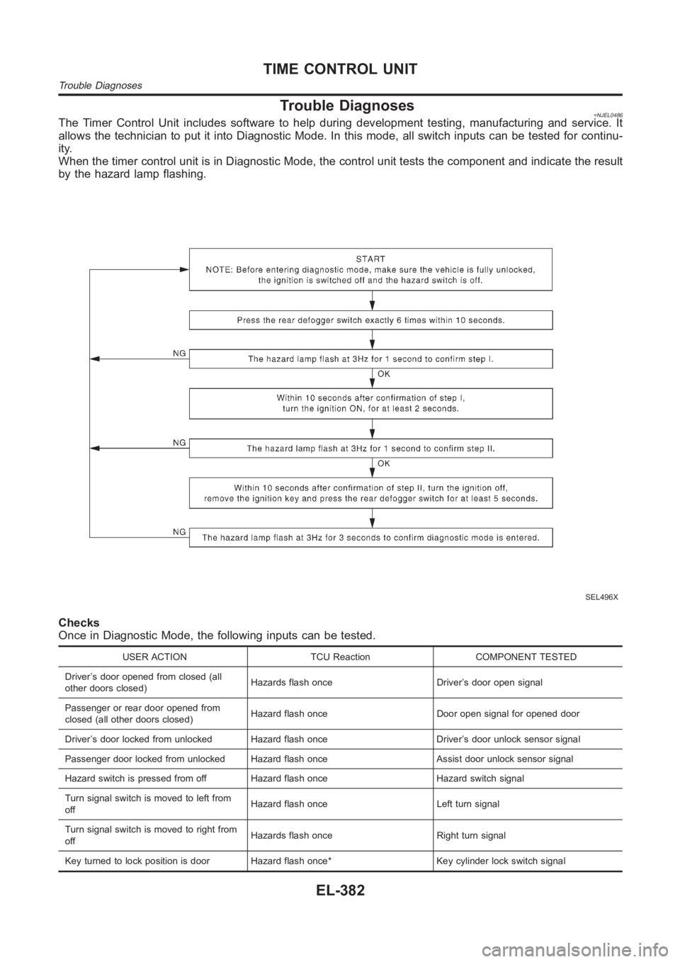
Trouble Diagnoses=NJEL0486The Timer Control Unit includes software to help during development testing, manufacturing and service. It
allows the technician to put it into Diagnostic Mode. In this mode, all switch inputs can be tested for continu-
ity.
When the timer control unit is in Diagnostic Mode, the control unit tests the component and indicate the result
by the hazard lamp flashing.
SEL496X
Checks
Once in Diagnostic Mode, the following inputs can be tested.
USER ACTION TCU Reaction COMPONENT TESTED
Driver’s door opened from closed (all
other doors closed)Hazards flash once Driver’s door open signal
Passenger or rear door opened from
closed (all other doors closed)Hazard flash once Door open signal for opened door
Driver’s door locked from unlocked Hazard flash once Driver’s door unlocksensor signal
Passenger door locked from unlocked Hazard flash once Assist door unlock sensor signal
Hazard switch is pressed from off Hazard flash once Hazard switch signal
Turn signal switch is moved to left from
offHazard flash once Left turn signal
Turn signal switch is moved to right from
offHazards flash once Right turn signal
Key turned to lock position is door Hazard flash once* Key cylinder lock switch signal
TIME CONTROL UNIT
Trouble Diagnoses
EL-382