Idler pulley removal NISSAN ALMERA N16 2003 Electronic Repair Manual
[x] Cancel search | Manufacturer: NISSAN, Model Year: 2003, Model line: ALMERA N16, Model: NISSAN ALMERA N16 2003Pages: 3189, PDF Size: 54.76 MB
Page 91 of 3189
![NISSAN ALMERA N16 2003 Electronic Repair Manual DRIVE BELTS
EM-13
[QG]
C
D
E
F
G
H
I
J
K
L
MA
EM
Removal and InstallationEBS00LQ0
REMOVAL
●Loosen each belt while referring to “Tension Adjustment”, and remove them one by one starting from the
NISSAN ALMERA N16 2003 Electronic Repair Manual DRIVE BELTS
EM-13
[QG]
C
D
E
F
G
H
I
J
K
L
MA
EM
Removal and InstallationEBS00LQ0
REMOVAL
●Loosen each belt while referring to “Tension Adjustment”, and remove them one by one starting from the](/img/5/57350/w960_57350-90.png)
DRIVE BELTS
EM-13
[QG]
C
D
E
F
G
H
I
J
K
L
MA
EM
Removal and InstallationEBS00LQ0
REMOVAL
●Loosen each belt while referring to “Tension Adjustment”, and remove them one by one starting from the
one in front.
INSTALLATION
1. Install belts to pulley in reverse order of removal.
2. Adjust belt tension.
CAUTION:
●When checking belt tension immediately after installation, first, adjust to specified value. Then,
after turning crankshaft more than two turns, re-adjust to specified value to avoid variation in
deflection between pulleys.
●Tighten idler pulley lock nut by hand and measure tension without looseness.
3. Tighten each adjusting bolt and nut to the specified torque.
4. Make sure that tension of each belt is within the standard.
Page 131 of 3189
![NISSAN ALMERA N16 2003 Electronic Repair Manual TIMING CHAIN
EM-53
[QG]
C
D
E
F
G
H
I
J
K
L
MA
EM
h. Install front cover with mounting bolts temporarily so that front
cover will not move.
i. Press fit dowel pin into cylinder block through NISSAN ALMERA N16 2003 Electronic Repair Manual TIMING CHAIN
EM-53
[QG]
C
D
E
F
G
H
I
J
K
L
MA
EM
h. Install front cover with mounting bolts temporarily so that front
cover will not move.
i. Press fit dowel pin into cylinder block through](/img/5/57350/w960_57350-130.png)
TIMING CHAIN
EM-53
[QG]
C
D
E
F
G
H
I
J
K
L
MA
EM
h. Install front cover with mounting bolts temporarily so that front
cover will not move.
i. Press fit dowel pin into cylinder block through front cover.
j. Tighten front cover mounting bolts temporarily.
●A [M6 x 20 mm (0.79 in)], B [M6 x 40 mm (1.57 in)], C [M8 x
70 mm (2.76 in)], D [M6 x 73 mm (2.87 in)]
●Bolt C also secures power steering pump adjusting bar.
●Bolt E [M6 x 12 mm (0.47 in)] is for installing power steering
pump adjusting bar.
k. Tighten cylinder head auxiliary bolts (M6) temporarily.
l. Tighten front cover mounting bolts and cylinder head auxiliary
bolts to specified torque.
4. Install oil pump drive spacer.
●When installing, align with flat of oil pump inner rotor.
●If they are not aligned, rotate inner rotor with a flat-bladed
screwdriver to align them.
CAUTION:
Be careful not to damage oil seal lips.
5. Install water pump pulley and idler pulley bracket assembly.
6. Install crankshaft pulley.
●When installing it, make sure that front oil seal lip is not inverted and garter spring is in position.
●For direction of mounting bolt washer, refer to “Component Parts Location”.
●With same procedure as “removal”, secure crankshaft, and tighten mounting bolts.
7. Install cylinder head front cover.
●Apply liquid gasket to cylinder head front cover.
●Use Genuine Liquid Gasket or equivalent.
8. Install engine front mounting bracket.
9. Install remaining parts in the reverse order of removal.
INSPECTION AFTER INSTALLATION
●In order to allow liquid gasket to be cured, perform inspection at least 30 minutes after the last step in
which parts sealed with liquid gasket are installed.
●With engine warmed up, check each part for engine oil leakage.
PBIC0564E
EMD0850D
PBIC0566E
PBIC0968E
Page 196 of 3189

If the belt deflection of the current belt is out of the “Limit
for re-tightening”, adjust to the “Adjusted value”.
When checking belt deflection immediately after
installation, first adjust it to the specified value. Then,
after turning crankshaft two turns or more, re-adjust it to
the specified value to avoid variation in deflection
between pulleys.
Make sure the belts are fully fitted into the pulley grooves
during installation.
Handle with care to avoid smearing the belts with oil or
cooling water etc.
Do not twist or bend the belts with strong force.
JEM251G
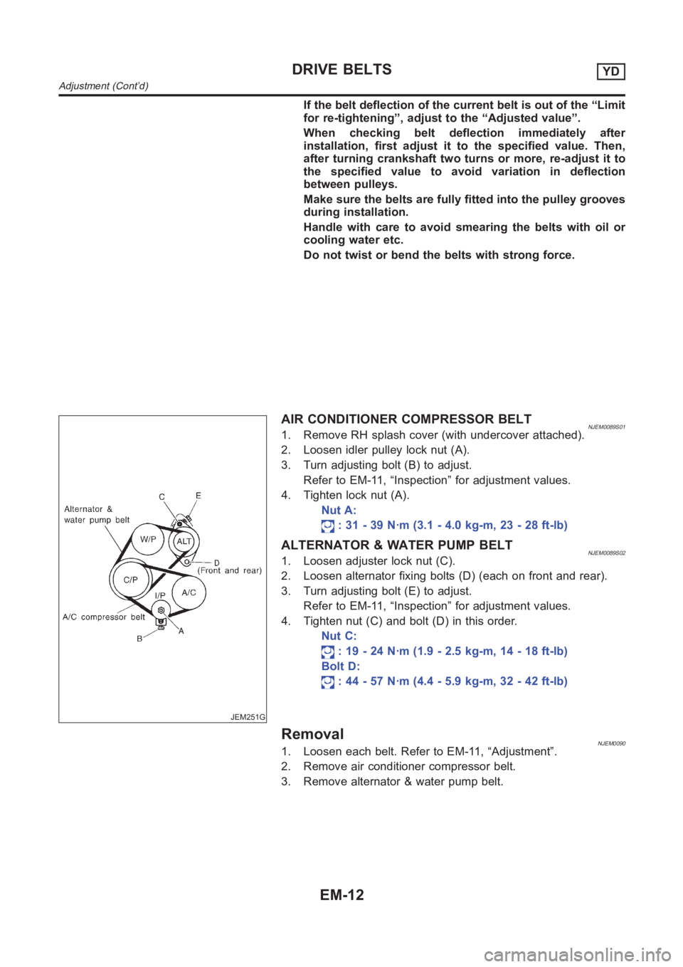
AIR CONDITIONER COMPRESSOR BELTNJEM0089S011. Remove RH splash cover (with undercover attached).
2. Loosen idler pulley lock nut (A).
3. Turn adjusting bolt (B) to adjust.
Refer to EM-11, “Inspection” for adjustment values.
4. Tighten lock nut (A).
Nut A:
: 31 - 39 N·m (3.1 - 4.0 kg-m, 23 - 28 ft-lb)
ALTERNATOR & WATER PUMP BELTNJEM0089S021. Loosen adjuster lock nut (C).
2. Loosen alternator fixing bolts (D) (each on front and rear).
3. Turn adjusting bolt (E) to adjust.
Refer to EM-11, “Inspection” for adjustment values.
4. Tighten nut (C) and bolt (D) in this order.
Nut C:
: 19 - 24 N·m (1.9 - 2.5 kg-m, 14 - 18 ft-lb)
Bolt D:
: 44 - 57 N·m (4.4 - 5.9 kg-m, 32 - 42 ft-lb)
RemovalNJEM00901. Loosen each belt. Refer to EM-11, “Adjustment”.
2. Remove air conditioner compressor belt.
3. Remove alternator & water pump belt.
DRIVE BELTSYD
Adjustment (Cont’d)
EM-12
Page 296 of 3189

Water Pump
REMOVAL AND INSTALLATIONNJLC0018
SEM858F
SEM859F
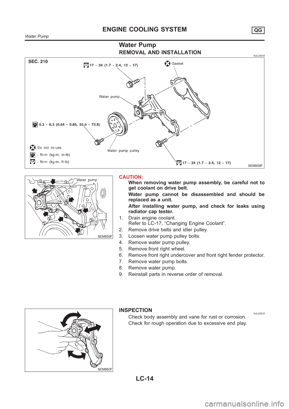
CAUTION:
When removing water pump assembly, be careful not to
get coolant on drive belt.
Water pump cannot be disassembled and should be
replaced as a unit.
After installing water pump, and check for leaks using
radiator cap tester.
1. Drain engine coolant.
Refer to LC-17, “Changing Engine Coolant”.
2. Remove drive belts and idler pulley.
3. Loosen water pump pulley bolts.
4. Remove water pump pulley.
5. Remove front right wheel.
6. Remove front right undercover and front right fender protector.
7. Remove water pump bolts.
8. Remove water pump.
9. Reinstall parts in reverse order of removal.
SEM860F
INSPECTIONNJLC0019Check body assembly and vane for rust or corrosion.
Check for rough operation due to excessive end play.
ENGINE COOLING SYSTEMQG
Water Pump
LC-14
Page 3139 of 3189

MEL497L
MEL145L
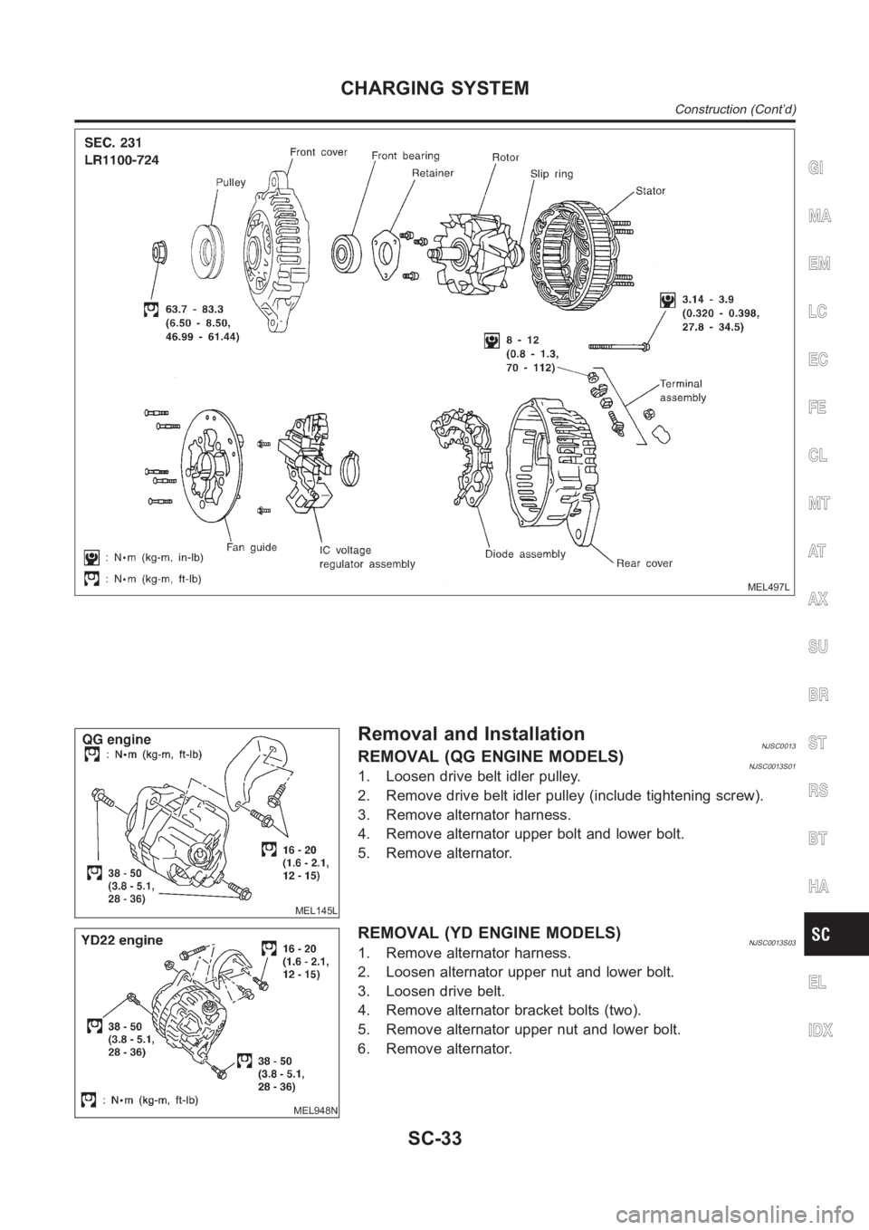
Removal and InstallationNJSC0013REMOVAL (QG ENGINE MODELS)NJSC0013S011. Loosen drive belt idler pulley.
2. Remove drive belt idler pulley (include tightening screw).
3. Remove alternator harness.
4. Remove alternator upper bolt and lower bolt.
5. Remove alternator.
MEL948N
REMOVAL (YD ENGINE MODELS)NJSC0013S031. Remove alternator harness.
2. Loosen alternator upper nut and lower bolt.
3. Loosen drive belt.
4. Remove alternator bracket bolts (two).
5. Remove alternator upper nut and lower bolt.
6. Remove alternator.
GI
MA
EM
LC
EC
FE
CL
MT
AT
AX
SU
BR
ST
RS
BT
HA
EL
IDX
CHARGING SYSTEM
Construction (Cont’d)
SC-33