auxiliary battery NISSAN ALMERA N16 2003 Electronic Repair Manual
[x] Cancel search | Manufacturer: NISSAN, Model Year: 2003, Model line: ALMERA N16, Model: NISSAN ALMERA N16 2003Pages: 3189, PDF Size: 54.76 MB
Page 126 of 3189
![NISSAN ALMERA N16 2003 Electronic Repair Manual EM-48
[QG]
TIMING CHAIN
2. Disconnect battery ground cable.
3. Remove undercover, front RH wheel and RH splash cover.
4. Drain engine coolant from radiator and cylinder block. Refer to LC-17, "Cha NISSAN ALMERA N16 2003 Electronic Repair Manual EM-48
[QG]
TIMING CHAIN
2. Disconnect battery ground cable.
3. Remove undercover, front RH wheel and RH splash cover.
4. Drain engine coolant from radiator and cylinder block. Refer to LC-17, "Cha](/img/5/57350/w960_57350-125.png)
EM-48
[QG]
TIMING CHAIN
2. Disconnect battery ground cable.
3. Remove undercover, front RH wheel and RH splash cover.
4. Drain engine coolant from radiator and cylinder block. Refer to LC-17, "Changing Engine Coolant".
5. Drain engine oil from oil pan.
6. Remove drive belt. Refer to EM-13, "
Removal and Installation" .
7. Remove power steering pump from adjusting bar.
8. Remove alternator. SC-33, "Removal and Installation".
9. Remove ignition coils. Refer to EM-24, "
IGNITION COIL" .
10. Remove rocker cover. Refer to EM-29, "
Removal and Installation" .
11. Remove oil level gauge.
12. Remove exhaust front tube. Refer to FE-10, "Removal and Installation".
13. Remove center member.
14. Remove gusset.
15. Remove rear plate (lower) (A/T models).
16. Remove oil pan and oil strainer. Refer to EM-22, "
Removal and Installation" .
17. For safe operation, and to reduce load to mount insulator, install removed center member again.
18. Remove engine front-side (right side of vehicle) engine mount. Refer to EM-67, "
ENGINE ASSEMBLY" .
a. Remove any parts that cause difficulties for operation around mount, or perform transfer.
b. Support cylinder block bottom surface with a transmission jack.
CAUTION:
●When applying jack, use a wooden block to avoid damage to oil pan mounting surface.
●While performing following operations, support engine front-side with jack.
c. Separate engine mounting insulator and bracket.
d. Remove engine mounting bracket.
19. Remove cylinder head front cover.
●Move harness which was previously fixed on front surface.
20. Remove auxiliary bolts of cylinder head.
21. Set the No. 1 cylinder to the compression TDC.
a. Turn the crankshaft pulley clockwise, and align the timing indica-
tor of the gear case to the timing mark of the crankshaft pulley.
PBIC0557E
PBIC0750E
Page 248 of 3189

crankshaft position sensor (TDC sensor) from the assem-
bly.
Always pay extra attention not to damage edge of crank-
shaft position sensor (TDC sensor) or ring gear teeth.
REMOVALNJEM0069S011. Remove engine undercover, and hood for hoisting.
2. Drain coolant from both cylinder block and radiator. Refer to
LC-43, “Changing Engine Coolant”.
3. Remove the following parts:
Battery
RH and LH front wheels
RH and LH splash covers (combined with undercover)
Auxiliary belts
Alternator
Alternator brackets
Radiator and cooling fan
Engine cover
Air ducts and air cleaner case
LH side of engine room:
4. Disconnect all harnesses and grounds that are connected to
components on vehicle.
5. Disconnect vacuum hose on vacuum pump side.
6. Disconnect fuel feed and fuel return hoses on engine side.
Immediately put blind plugs into the openings to prevent
fuel from flowing out.
7. Disconnect heater hose. Plug opening of hose to prevent cool-
ant from flowing out.
RH side of engine room:
8. Remove air conditioner compressor from brackets and move
it toward vehicle side. Secure compressor on vehicle side with
rope.
Vehicle underside:
9. Remove exhaust front tube.
10. Disconnect two hoses from power steering pump and plug to
stop fluid.
11. Remove M/T control rod and support rod.
12. Remove ABS wheel sensor, and temporarily hang brake cali-
per with rope on vehicle side.
13. Remove RH and LH drive shafts.
YEM024
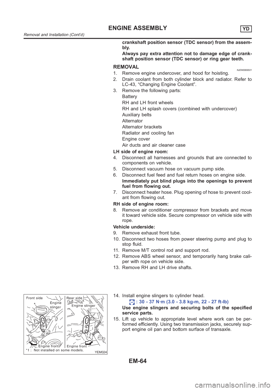
14. Install engine slingers to cylinder head.
: 30 - 37 N·m (3.0 - 3.8 kg-m, 22 - 27 ft-lb)
Use engine slingers and securing bolts of the specified
service parts.
15. Lift up vehicle to appropriate level where work can be per-
formed efficiently. Using two transmission jacks, securely sup-
port engine oil pan and bottom surface of transaxle.
ENGINE ASSEMBLYYD
Removal and Installation (Cont’d)
EM-64
Page 2549 of 3189

Trouble DiagnosesNJEL0385AUDIO UNITNJEL0385S05
Symptom Possible causes Repair order
Audio unit inoperative (no
digital display and no
sound from speakers).1. 10A fuse
2. Poor audio unit case ground
3. Audio unit1. Check 10A fuse. Turn ignition switch ON and verify
that battery positive voltage is present at the termi-
nal of audio unit.
2. Check audio unit case ground.
3. Remove audio unit for repair.
Audio unit presets are lost
when ignition switch is
turned OFF.1. 15A fuse
2. Audio unit1. Check 15A fuse and verify that battery positive volt-
age is present at the terminal of audio unit.
2. Remove audio unit for repair.
Individual rear speaker is
noisy or inoperative.1. Each speaker
2. Output circuit to each speaker1. Check speaker.
2. Check the output circuits to each speaker
between audio unit and speaker amp.
between speaker amp. and each speaker.
AM/FM stations are weak
or noisy.1. Roof antenna
2. Audio unit ground
3. Audio unit1. Check roof antenna.
2. Check audio unit ground condition.
3. Remove audio unit for repair.
Audio unit generates noise
in AM and FM modes with
engine running.1. Poor audio unit ground
2. Loose or missing ground bonding straps
3. Ignition condenser or rear window defog-
ger noise suppressor condenser
4. Ignition coil or secondary wiring
5. Audio unit1. Check audio unit ground.
2. Check ground bonding straps.
3. Replace ignition condenser or rear window defogger
noise suppressor condenser.
4. Check ignition coil and secondary wiring.
5. Remove audio unit for repair.
Audio unit generates noise
in AM and FM modes with
accessories on (switch
pops and motor noise).1. Poor audio unit ground
2. Antenna
3. Accessory ground
4. Faulty accessory1. Check audio unit ground.
2. Check antenna.
3. Check accessory ground.
4. Replace accessory.
InspectionNJEL0221AUDIO UNITNJEL0221S01All voltage inspections are made with:
Ignition switch ON or ACC
Audio unit ON
Audio unit connected (If audio unit is removed for inspection, supply a ground to the case using a jumper
wire.)
ANTENNANJEL0221S02Using a jumper wire, clip an auxiliary ground between antenna and body.
If reception improves, check antenna ground (at body surface).
If reception does not improve, check main feeder cable for short circuit oropen circuit.
GI
MA
EM
LC
EC
FE
CL
MT
AT
AX
SU
BR
ST
RS
BT
HA
SC
IDX
AUDIO
Trouble Diagnoses
EL-213