charging NISSAN ALMERA N16 2003 Electronic Repair Manual
[x] Cancel search | Manufacturer: NISSAN, Model Year: 2003, Model line: ALMERA N16, Model: NISSAN ALMERA N16 2003Pages: 3189, PDF Size: 54.76 MB
Page 1 of 3189

Edition: August 2003
Release: October 2003 (01)
Publication No.: SM3E00-1N16E1E
Reference No.: 7711347018
GENERAL INFORMATIONGI
MAINTENANCEMA
ENGINE MECHANICAL – QGEM-QG
ENGINE MECHANICAL – YDEM-YD
ENGINE LUBRICATION &
COOLING SYSTEMSLC
ENGINE CONTROL SYSTEM – QGEC - QG
ENGINE CONTROL SYSTEM – YDEC - YD
ACCELERATOR CONTROL,
FUEL & EXHAUST SYSTEMSFE
CLUTCHCL
MANUAL TRANSAXLEMT
AUTOMATIC TRANSAXLEAT
FRONT & REAR AXLEAX
FRONT & REAR SUSPENSIONSU
BRAKE SYSTEMBR
STEERING SYSTEMST
RESTRAINT SYSTEMRS
BODY & TRIMBT
HEATER & MANUAL AIR CONDITIONERHA
AUTOMATIC AIR CONDITIONERATC
STARTING & CHARGING SYSTEMSSC
ELECTRICAL SYSTEMEL
ALPHABETICAL INDEXIDX
ALMERA
MODEL N16 SERIES
NISSAN EUROPE S.A.S.
© 2003 NISSAN EUROPE S.A.S.
Produced in The Netherlands
Not to be reproduced in whole or in part
without the prior written permission of
Nissan Europe S.A.S., Paris, France.
QUICK REFERENCE INDEX
Page 711 of 3189
![NISSAN ALMERA N16 2003 Electronic Repair Manual FUEL PUMP CIRCUIT
EC-381
[QG (WITH EURO-OBD)]
C
D
E
F
G
H
I
J
K
L
MA
EC
FUEL PUMP CIRCUITPFP:17042
DescriptionEBS00KD3
SYSTEM DESCRIPTION
*: The ECM determines the start signal status by the signals o NISSAN ALMERA N16 2003 Electronic Repair Manual FUEL PUMP CIRCUIT
EC-381
[QG (WITH EURO-OBD)]
C
D
E
F
G
H
I
J
K
L
MA
EC
FUEL PUMP CIRCUITPFP:17042
DescriptionEBS00KD3
SYSTEM DESCRIPTION
*: The ECM determines the start signal status by the signals o](/img/5/57350/w960_57350-710.png)
FUEL PUMP CIRCUIT
EC-381
[QG (WITH EURO-OBD)]
C
D
E
F
G
H
I
J
K
L
MA
EC
FUEL PUMP CIRCUITPFP:17042
DescriptionEBS00KD3
SYSTEM DESCRIPTION
*: The ECM determines the start signal status by the signals of engine speed and battery voltage.
The ECM activates the fuel pump for several seconds after the ignition switch is turned on to improve engine
startability. If the ECM receives a engine speed signal from the crankshaft position sensor (POS) and cam-
shaft position sensor (PHASE), it knows that the engine is rotating, and causes the pump to operate. If the
engine speed signal is not received when the ignition switch is ON, the engine stalls. The ECM stops pump
operation and prevents battery discharging, thereby improving safety. The ECM does not directly drive the fuel
pump. It controls the ON/OFF fuel pump relay, which in turn controls the fuel pump.
COMPONENT DESCRIPTION
A turbine type design fuel pump is used in the fuel tank.
CONSULT-II Reference Value in Data Monitor ModeEBS00KD4
Specification data are reference values.
Sensor Input Signal to ECM ECM Function Actuator
Crankshaft position sensor (POS)
Camshaft position sensor (PHASE)Engine speed
*
Fuel pump control Fuel pump relay
Battery
Battery voltage
*
Condition Fuel pump operation
Ignition switch is turned to ON. Operates for 1 second.
Engine running and crankingOperates.
When engine is stoppedStops in 1.5 seconds.
Except as shown aboveStops.
MBIB0046E
MONITOR ITEM CONDITION SPECIFICATION
FUEL PUMP RLY
●For 1 seconds after turning ignition switch ON
●Engine running or crankingON
●Except above conditions OFF
Page 1029 of 3189
![NISSAN ALMERA N16 2003 Electronic Repair Manual FUEL PUMP CIRCUIT
EC-699
[QG (WITHOUT EURO-OBD)]
C
D
E
F
G
H
I
J
K
L
MA
EC
FUEL PUMP CIRCUITPFP:17042
DescriptionEBS00KM1
SYSTEM DESCRIPTION
*: The ECM determines the start signal status by the signal NISSAN ALMERA N16 2003 Electronic Repair Manual FUEL PUMP CIRCUIT
EC-699
[QG (WITHOUT EURO-OBD)]
C
D
E
F
G
H
I
J
K
L
MA
EC
FUEL PUMP CIRCUITPFP:17042
DescriptionEBS00KM1
SYSTEM DESCRIPTION
*: The ECM determines the start signal status by the signal](/img/5/57350/w960_57350-1028.png)
FUEL PUMP CIRCUIT
EC-699
[QG (WITHOUT EURO-OBD)]
C
D
E
F
G
H
I
J
K
L
MA
EC
FUEL PUMP CIRCUITPFP:17042
DescriptionEBS00KM1
SYSTEM DESCRIPTION
*: The ECM determines the start signal status by the signals of engine speed and battery voltage.
The ECM activates the fuel pump for several seconds after the ignition switch is turned on to improve engine
startability. If the ECM receives a engine speed signal from the crankshaft position sensor (POS) and cam-
shaft position sensor (PHASE), it knows that the engine is rotating, and causes the pump to operate. If the
engine speed signal is not received when the ignition switch is ON, the engine stalls. The ECM stops pump
operation and prevents battery discharging, thereby improving safety. The ECM does not directly drive the fuel
pump. It controls the ON/OFF fuel pump relay, which in turn controls the fuel pump.
COMPONENT DESCRIPTION
A turbine type design fuel pump is used in the fuel tank.
CONSULT-II Reference Value in Data Monitor ModeEBS00KM2
Specification data are reference values.
Sensor Input Signal to ECM ECM Function Actuator
Crankshaft position sensor (POS)
Camshaft position sensor (PHASE)Engine speed
*
Fuel pump control Fuel pump relay
Battery
Battery voltage
*
Condition Fuel pump operation
Ignition switch is turned to ON. Operates for 1 second.
Engine running and crankingOperates.
When engine is stoppedStops in 1.5 seconds.
Except as shown aboveStops.
MBIB0046E
MONITOR ITEM CONDITION SPECIFICATION
FUEL PUMP RLY
●For 1 seconds after turning ignition switch ON
●Engine running or crankingON
●Except above conditions OFF
Page 1469 of 3189

A/T FLUID
AT-13
D
E
F
G
H
I
J
K
L
MA
B
AT
A/T FLUIDPFP:KLE40
Checking A/T FluidECS007NC
1. Warm up engine.
2. Check for fluid leakage.
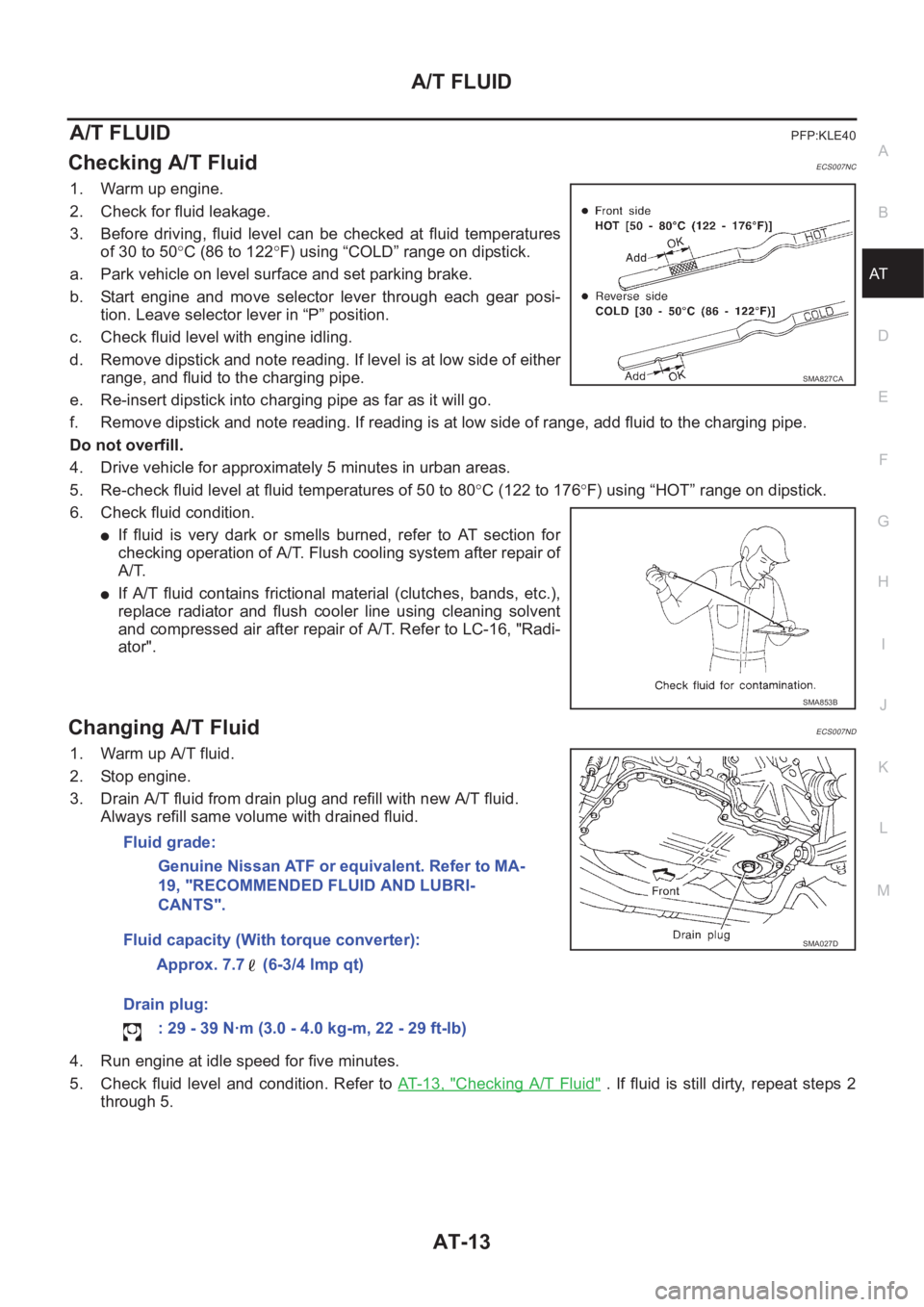
3. Before driving, fluid level can be checked at fluid temperatures
of 30 to 50°C (86 to 122°F) using “COLD” range on dipstick.
a. Park vehicle on level surface and set parking brake.
b. Start engine and move selector lever through each gear posi-
tion. Leave selector lever in “P” position.
c. Check fluid level with engine idling.
d. Remove dipstick and note reading. If level is at low side of either
range, and fluid to the charging pipe.
e. Re-insert dipstick into charging pipe as far as it will go.
f. Remove dipstick and note reading. If reading is at low side of range, add fluid to the charging pipe.
Do not overfill.
4. Drive vehicle for approximately 5 minutes in urban areas.
5. Re-check fluid level at fluid temperatures of 50 to 80°C (122 to 176°F) using “HOT” range on dipstick.
6. Check fluid condition.
●If fluid is very dark or smells burned, refer to AT section for
checking operation of A/T. Flush cooling system after repair of
A/T.
●If A/T fluid contains frictional material (clutches, bands, etc.),
replace radiator and flush cooler line using cleaning solvent
and compressed air after repair of A/T. Refer to LC-16, "Radi-
ator".
Changing A/T FluidECS007ND
1. Warm up A/T fluid.
2. Stop engine.
3. Drain A/T fluid from drain plug and refill with new A/T fluid.
Always refill same volume with drained fluid.
4. Run engine at idle speed for five minutes.
5. Check fluid level and condition. Refer to AT- 1 3 , "
Checking A/T Fluid" . If fluid is still dirty, repeat steps 2
through 5.
SMA827CA
SMA853B
Fluid grade:
Genuine Nissan ATF or equivalent. Refer to MA-
19, "RECOMMENDED FLUID AND LUBRI-
CANTS".
Fluid capacity (With torque converter):
Approx. 7.7 (6-3/4 lmp qt)
Drain plug:
: 29 - 39 N·m (3.0 - 4.0 kg-m, 22 - 29 ft-lb)
SMA027D
Page 1559 of 3189
![NISSAN ALMERA N16 2003 Electronic Repair Manual TROUBLE DIAGNOSIS — GENERAL DESCRIPTION
AT-103
[EURO-OBD]
D
E
F
G
H
I
J
K
L
MA
B
AT
Offensive smell at fluid charging
pipe.ON vehicle 1. Fluid levelAT-63, "
FLUID LEVEL
CHECK"
OFF vehicle2 NISSAN ALMERA N16 2003 Electronic Repair Manual TROUBLE DIAGNOSIS — GENERAL DESCRIPTION
AT-103
[EURO-OBD]
D
E
F
G
H
I
J
K
L
MA
B
AT
Offensive smell at fluid charging
pipe.ON vehicle 1. Fluid levelAT-63, "
FLUID LEVEL
CHECK"
OFF vehicle2](/img/5/57350/w960_57350-1558.png)
TROUBLE DIAGNOSIS — GENERAL DESCRIPTION
AT-103
[EURO-OBD]
D
E
F
G
H
I
J
K
L
MA
B
AT
Offensive smell at fluid charging
pipe.ON vehicle 1. Fluid levelAT-63, "
FLUID LEVEL
CHECK"
OFF vehicle2. Torque converterAT-417, "
Locations of
Adjusting Shims, Needle
Bearings, Thrust Washers
and Snap Rings"
3. Oil pumpAT-435, "Oil Pump"
4. Reverse clutchAT-455, "Reverse Clutch"
5. High clutchAT-459, "High Clutch"
6. Brake bandAT-483, "Band Servo Pis-
ton Assembly"
7. Forward clutchAT-464, "Forward and
Overrun Clutches"
8. Overrun clutchAT-464, "Forward and
Overrun Clutches"
9. Low & reverse brakeAT-470, "Low & Reverse
Brake"
Torque converter is not locked up.ON vehicle1. Throttle position sensor [Accelerator
pedal position (APP) sensor]AT-181, "
DTC P1705
ACCELERATOR PEDAL
POSITION (APP) SEN-
SOR"
2. Vehicle speed sensor·A/T (Revolution
sensor) and vehicle speed sensor·MTRAT-123, "
DTC P0720 VEHI-
CLE SPEED SENSOR A/T
(REVOLUTION SEN-
SOR)",AT-201, "DTC
VEHICLE SPEED SEN-
SOR MTR"
3. PNP switch adjustmentAT-408, "
Park/Neutral Posi-
tion (PNP) Switch Adjust-
ment"
4. Engine speed signalAT-129, "DTC P0725
ENGINE SPEED SIGNAL"
5. A/T fluid temp sen circ and TCM pow sourAT-195, "
DTC BATT/FLUID
TEMP SEN (A/T FLUID
TEMP SENSOR CIRCUIT
AND TCM POWER
SOURCE)"
6. Line pressure testAT-67, "Line Pressure Test"
7. Torque converter clutch solenoid valveAT-159, "
DTC P0740
TORQUE CONVERTER
CLUTCH SOLENOID
VA LV E"
8. Control valve assemblyAT-406, "
Control Valve
Assembly and Accumula-
tors"
OFF vehicle 9. Torque converterAT-417, "
Locations of
Adjusting Shims, Needle
Bearings, Thrust Washers
and Snap Rings"
Symptom Condition Diagnostic ItemReference Page
EURO-OBD
Page 1755 of 3189
![NISSAN ALMERA N16 2003 Electronic Repair Manual TROUBLE DIAGNOSIS — GENERAL DESCRIPTION
AT-299
[EXC.F/EURO-OBD]
D
E
F
G
H
I
J
K
L
MA
B
AT
Offensive smell at fluid charging pipe.ON vehicle 1. Fluid levelAT- 2 6 1 , "
FLUID LEVEL
CHECK"
NISSAN ALMERA N16 2003 Electronic Repair Manual TROUBLE DIAGNOSIS — GENERAL DESCRIPTION
AT-299
[EXC.F/EURO-OBD]
D
E
F
G
H
I
J
K
L
MA
B
AT
Offensive smell at fluid charging pipe.ON vehicle 1. Fluid levelAT- 2 6 1 , "
FLUID LEVEL
CHECK"](/img/5/57350/w960_57350-1754.png)
TROUBLE DIAGNOSIS — GENERAL DESCRIPTION
AT-299
[EXC.F/EURO-OBD]
D
E
F
G
H
I
J
K
L
MA
B
AT
Offensive smell at fluid charging pipe.ON vehicle 1. Fluid levelAT- 2 6 1 , "
FLUID LEVEL
CHECK"
OFF vehicle2. Torque converterAT- 4 1 7 , "
Locations of
Adjusting Shims, Needle
Bearings, Thrust Washers
and Snap Rings"
3. Oil pumpAT- 4 3 5 , "Oil Pump"
4. Reverse clutchAT- 4 5 5 , "Reverse Clutch"
5. High clutchAT- 4 5 9 , "High Clutch"
6. Brake bandAT- 4 8 3 , "Band Servo Pis-
ton Assembly"
7. Forward clutchAT- 4 6 4 , "Forward and
Overrun Clutches"
8. Overrun clutchAT- 4 6 4 , "Forward and
Overrun Clutches"
9. Low & reverse brakeAT- 4 7 0 , "Low & Reverse
Brake"
Torque converter is not locked up.ON vehicle1. Throttle position sensor (Accelerator
pedal position (APP) sensor)AT- 3 5 2 , "
ACCELE
RATOR PEDAL POSI-
TION (APP) SENSOR"
2. Vehicle speed sensor·A/T (Revolution
sensor) and vehicle speed sensor·MTRAT- 3 4 3 , "
VEHICLE
SPEED SENSOR - A/T
(REVOLUTION SEN-
SOR)",AT-348, "DTC
VEHICLE SPEED SEN-
SOR MTR"
3. PNP switch adjustmentAT- 4 0 8 , "
Park/Neutral
Position (PNP) Switch
Adjustment"
4. Engine speed signalAT- 3 8 3 , "ENGINE SPEED
SIGNAL"
5. A/T fluid temp sen circ and TCM pow
sourAT- 3 7 7 , "
BATT/FLUID
TEMP SEN (A/T FLUID
TEMP SENSOR CIR-
CUIT AND TCM POWER
SOURCE)"
6. Line pressure testAT- 2 6 5 , "Line Pressure
Te s t"
7. Torque converter clutch solenoid valveAT- 3 7 2 , "
TORQUE CON-
VERTER CLUTCH
SOLENOID VALVE"
8. Control valve assemblyAT- 4 0 6 , "
Control Valve
Assembly and Accumula-
tors"
OFF vehicle 9. Torque converterAT- 4 1 7 , "
Locations of
Adjusting Shims, Needle
Bearings, Thrust Washers
and Snap Rings"
Symptom Condition Diagnostic Item Reference Page
Page 1875 of 3189
![NISSAN ALMERA N16 2003 Electronic Repair Manual DISASSEMBLY
AT-419
[ALL]
D
E
F
G
H
I
J
K
L
MA
B
AT
4. Remove A/T fluid charging pipe and fluid cooler tube.
5. Set manual shaft to position P.
6. Remove park/neutral position (PNP) switch.
7. Remove o NISSAN ALMERA N16 2003 Electronic Repair Manual DISASSEMBLY
AT-419
[ALL]
D
E
F
G
H
I
J
K
L
MA
B
AT
4. Remove A/T fluid charging pipe and fluid cooler tube.
5. Set manual shaft to position P.
6. Remove park/neutral position (PNP) switch.
7. Remove o](/img/5/57350/w960_57350-1874.png)
DISASSEMBLY
AT-419
[ALL]
D
E
F
G
H
I
J
K
L
MA
B
AT
4. Remove A/T fluid charging pipe and fluid cooler tube.
5. Set manual shaft to position P.
6. Remove park/neutral position (PNP) switch.
7. Remove oil pan and oil pan gasket.
●Do not reuse oil pan bolts.
8. Check foreign materials in oil pan to help determine causes of
malfunction. If the fluid is very dark, smells burned, or contains
foreign particles, the frictional material (clutches, band) may
need replacement. A tacky film that will not wipe clean indicates
varnish build up. Varnish can cause valves, servo, and clutches
to stick and can inhibit pump pressure.
●If frictional material is detected, replace radiator after
repair of A/T. Refer to LC-16, "RADIATOR".
9. Remove control valve assembly according to the following pro-
cedures.
a. Remove control valve assembly mounting bolts A, B and C.
MCIB9012E
SAT023JA
SAT128E
AAT260A
Page 1970 of 3189
![NISSAN ALMERA N16 2003 Electronic Repair Manual AT-514
[ALL]
ASSEMBLY
21. Install A/T fluid charging pipe and fluid cooler tube to transmis-
sion case. Tighten A/T fluid charging pipe and fluid cooler tube
bolts to the specified NISSAN ALMERA N16 2003 Electronic Repair Manual AT-514
[ALL]
ASSEMBLY
21. Install A/T fluid charging pipe and fluid cooler tube to transmis-
sion case. Tighten A/T fluid charging pipe and fluid cooler tube
bolts to the specified](/img/5/57350/w960_57350-1969.png)
AT-514
[ALL]
ASSEMBLY
21. Install A/T fluid charging pipe and fluid cooler tube to transmis-
sion case. Tighten A/T fluid charging pipe and fluid cooler tube
bolts to the specified torque. Refer to AT- 4 1 3 , "
OVERHAUL" .
22. Install torque converter.
a. Pour ATF into torque converter.
●Approximately 1 liter (1-3/4 Imp pt) of fluid is required for
a new torque converter.
●When reusing old torque converter, add the same amount
of fluid as was drained.
b. Install torque converter while aligning notches of torque con-
verter with notches of oil pump.
c. Measure distance “A” to check that torque converter is in proper
position.
MCIB9012E
SAT428DA
SAT429D
Distance A:
Refer to AT- 5 1 5 , "
SERVICE DATA AND SPECIFICA-
TIONS (SDS)" .
SAT430D
Page 1981 of 3189

ATC-1
AUTOMATIC AIR CONDITIONER
J AIR CONDITIONER
CONTENTS
C
D
E
F
G
H
I
K
L
M
SECTION
A
B
AT C
AUTOMATIC AIR CONDITIONER
PRECAUTIONS .......................................................... 4
Precautions for Supplemental Restraint System
(SRS) “AIR BAG” and “SEAT BELT PRE-TEN-
SIONER” .................................................................. 4
Precautions for Working with HFC-134a (R-134a) ..... 4
General Refrigerant Precautions .............................. 4
Lubricant Precautions .............................................. 5
Precautions for Refrigerant Connection ................... 5
FEATURES OF NEW TYPE REFRIGERANT
CONNECTION ...................................................... 5
O-RING AND REFRIGERANT CONNECTION ..... 6
Precautions for Servicing Compressor ..................... 7
Precautions for Service Equipment .......................... 7
RECOVERY/RECYCLING EQUIPMENT .............. 7
ELECTRONIC LEAK DETECTOR ........................ 8
VACUUM PUMP ................................................... 8
MANIFOLD GAUGE SET ...................................... 8
SERVICE HOSES ................................................. 8
SERVICE COUPLERS .......................................... 9
REFRIGERANT WEIGHT SCALE ........................ 9
CALIBRATING ACR4 WEIGHT SCALE ................ 9
CHARGING CYLINDER ........................................ 9
Precautions for Leak Detection Dye ......................... 9
IDENTIFICATION ................................................ 10
IDENTIFICATION LABEL FOR VEHICLE ........... 10
Wiring Diagrams and Trouble Diagnosis ................ 10
PREPARATION ..........................................................11
Special Service Tools .............................................. 11
HFC-134a (R-134a) Service Tools and Equipment .... 11
REFRIGERATION SYSTEM ..................................... 15
Refrigerant Cycle ................................................... 15
REFRIGERANT FLOW ....................................... 15
FREEZE PROTECTION ..................................... 15
Refrigerant System Protection ............................... 15
REFRIGERANT PRESSURE SENSOR (WITH
GASOLINE ENGINE) .......................................... 15
DUAL-PRESSURE SWITCH (WITH DIESEL
ENGINE) ............................................................. 15
PRESSURE RELIEF VALVE ............................... 15
CSV613 Variable Displacement Compressor ......... 16GENERAL INFORMATION ................................. 16
DESCRIPTION .................................................... 16
Component Layout ................................................. 19
LUBRICANT .............................................................. 20
Maintenance of Lubricant Quantity in Compressor ... 20
LUBRICANT ........................................................ 20
LUBRICANT RETURN OPERATION .................. 20
LUBRICANT ADJUSTING PROCEDURE FOR
COMPONENTS REPLACEMENT EXCEPT
COMPRESSOR .................................................. 21
LUBRICANT ADJUSTING PROCEDURE FOR
COMPRESSOR REPLACEMENT ....................... 21
AIR CONDITIONER CONTROL ............................... 22
Overview Air Conditioner LAN Control System ...... 22
System Construction .............................................. 22
OPERATION ........................................................ 22
TRANSMISSION DATA AND TRANSMISSION
ORDER ............................................................... 23
AIR MIX DOOR CONTROL (AUTOMATIC TEM-
PERATURE CONTROL) ..................................... 23
FAN SPEED CONTROL ...................................... 24
INTAKE DOOR CONTROL ................................. 24
OUTLET DOOR CONTROL ................................ 24
MAGNET CLUTCH CONTROL ........................... 24
SELF-DIAGNOSTIC SYSTEM ............................ 24
Overview of Control system .................................... 24
Control Operation ................................................... 25
DISPLAY SCREEN .............................................. 25
AUTO SWITCH ................................................... 25
TEMPERATURE DIAL (POTENTIO TEMPERA-
TURE CONTROL) ............................................... 25
A/C SWITCH ....................................................... 25
DEFROSTER (DEF) SWITCH ............................. 25
MODE SWITCH .................................................. 25
FAN SWITCH ...................................................... 25
OFF SWITCH ...................................................... 25
FRESH (FRE) SWITCH ...................................... 25
RECIRCULATION (REC) SWITCH ..................... 26
REAR WINDOW DEFOGGER SWITCH ............. 26
Fail-safe Function ................................................... 26
Page 1987 of 3189

PRECAUTIONS
ATC-7
C
D
E
F
G
H
I
K
L
MA
B
AT C
●When installing an air conditioner in the vehicle, connect the pipes as the final stage of the opera-
tion. Do not remove the seal caps of pipes and other components until just before required for
connection.
●Allow components stored in cool areas to warm to working area temperature before removing seal
caps. This prevents condensation from forming inside A/C components.
●Thoroughly remove moisture from the refrigeration system before charging the refrigerant.
●Always replace used O-rings.
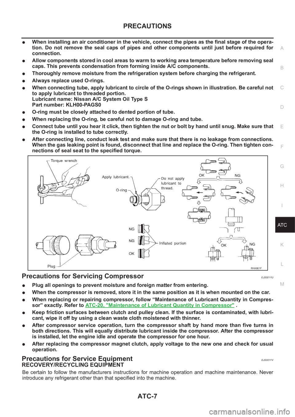
●When connecting tube, apply lubricant to circle of the O-rings shown in illustration. Be careful not
to apply lubricant to threaded portion.
Lubricant name: Nissan A/C System Oil Type S
Part number: KLH00-PAGS0
●O-ring must be closely attached to dented portion of tube.
●When replacing the O-ring, be careful not to damage O-ring and tube.
●Connect tube until you hear it click, then tighten the nut or bolt by hand until snug. Make sure that
the O-ring is installed to tube correctly.
●After connecting line, conduct leak test and make sure that there is no leakage from connections.
When the gas leaking point is found, disconnect that line and replace the O-ring. Then tighten con-
nections of seal seat to the specified torque.
Precautions for Servicing CompressorEJS001YU
●Plug all openings to prevent moisture and foreign matter from entering.
●When the compressor is removed, store it in the same position as it is when mounted on the car.
●When replacing or repairing compressor, follow “Maintenance of Lubricant Quantity in Compres-
sor” exactly. Refer to ATC-20, "
Maintenance of Lubricant Quantity in Compressor" .
●Keep friction surfaces between clutch and pulley clean. If the surface is contaminated, with lubri-
cant, wipe it off by using a clean waste cloth moistened with thinner.
●After compressor service operation, turn the compressor shaft by hand more than five turns in
both directions. This will equally distribute lubricant inside the compressor. After the compressor
is installed, let the engine idle and operate the compressor for one hour.
●After replacing the compressor magnet clutch, apply voltage to the new one and check for usual
operation.
Precautions for Service EquipmentEJS001YV
RECOVERY/RECYCLING EQUIPMENT
Be certain to follow the manufacturers instructions for machine operation and machine maintenance. Never
introduce any refrigerant other than that specified into the machine.
RHA861F