cooling fan wiring diagram NISSAN ALMERA N16 2003 Electronic Repair Manual
[x] Cancel search | Manufacturer: NISSAN, Model Year: 2003, Model line: ALMERA N16, Model: NISSAN ALMERA N16 2003Pages: 3189, PDF Size: 54.76 MB
Page 662 of 3189
![NISSAN ALMERA N16 2003 Electronic Repair Manual EC-332
[QG (WITH EURO-OBD)]
DTC P1217 ENGINE OVER TEMPERATURE
3. CHECK COOLING FAN MOTORS CIRCUIT
1. Turn ignition switch “OFF”.
2. Disconnect cooling fan motor-1 harness connector and cool NISSAN ALMERA N16 2003 Electronic Repair Manual EC-332
[QG (WITH EURO-OBD)]
DTC P1217 ENGINE OVER TEMPERATURE
3. CHECK COOLING FAN MOTORS CIRCUIT
1. Turn ignition switch “OFF”.
2. Disconnect cooling fan motor-1 harness connector and cool](/img/5/57350/w960_57350-661.png)
EC-332
[QG (WITH EURO-OBD)]
DTC P1217 ENGINE OVER TEMPERATURE
3. CHECK COOLING FAN MOTORS CIRCUIT
1. Turn ignition switch “OFF”.
2. Disconnect cooling fan motor-1 harness connector and cooling
fan motor-2 harness connector.
3. Check harness continuity between cooling fan relay-1 terminal 5
and cooling fan motor-1 terminal 1, cooling fan motor-1 terminal
2 and body ground.
Refer to Wiring Diagram.
4. Also check harness for short to ground and short to power.
5. Check harness continuity between cooling fan relay-1 terminal 7
and cooling fan motor-2 terminal 1, cooling fan motor-2 terminal
2 and body ground.
Refer to Wiring Diagram.
6. Also check harness for short to ground and short to power.
OK or NG
OK >> GO TO 4.
NG >> Repair open circuit or short to ground or short to power in harness or connectors.
4. CHECK COOLING FAN OUTPUT SIGNAL CIRCUIT FOR OPEN AND SHORT
1. Disconnect smart entrance control unit.
2. Check harness continuity between smart entrance control unit
terminal 33 and cooling fan relay-1 terminal 2.
Refer to Wiring Diagram.
3. Also check harness for short to ground and short to power.
OK or NG
OK >> GO TO 6.
NG >> GO TO 5.
5. DETECT MALFUNCTIONING PART
Check the following.
●Harness connectors E251, M182 (LHD models)
●Harness connectors E174, M159 (RHD models)
●Harness for open or short between smart entrance control unit and cooling fan relay-1
>> Repair open circuit or short to ground or short to power in harness or connectors.
6. CHECK COOLING FAN RELAY-1
Refer to EC-334, "
Component Inspection" .
OK or NG
OK >> GO TO 7.
NG >> Replace cooling fan relay.Continuity should exist.
Continuity should exist.
MBIB0252E
Continuity should exist.
MBIB0264E
Page 934 of 3189
![NISSAN ALMERA N16 2003 Electronic Repair Manual EC-604
[QG (WITHOUT EURO-OBD)]
DTC P1217 ENGINE OVER TEMPERATURE
3. CHECK COOLING FAN MOTORS CIRCUIT
1. Turn ignition switch “OFF”.
2. Disconnect cooling fan motor-1 harness connector and c NISSAN ALMERA N16 2003 Electronic Repair Manual EC-604
[QG (WITHOUT EURO-OBD)]
DTC P1217 ENGINE OVER TEMPERATURE
3. CHECK COOLING FAN MOTORS CIRCUIT
1. Turn ignition switch “OFF”.
2. Disconnect cooling fan motor-1 harness connector and c](/img/5/57350/w960_57350-933.png)
EC-604
[QG (WITHOUT EURO-OBD)]
DTC P1217 ENGINE OVER TEMPERATURE
3. CHECK COOLING FAN MOTORS CIRCUIT
1. Turn ignition switch “OFF”.
2. Disconnect cooling fan motor-1 harness connector and cooling
fan motor-2 harness connector.
3. Check harness continuity between cooling fan relay-1 terminal 5
and cooling fan motor-1 terminal 1, cooling fan motor-1 terminal
2 and body ground.
Refer to wiring diagram.
4. Also check harness for short to ground and short to power.
5. Check harness continuity between cooling fan relay-1 terminal 7
and cooling fan motor-2 terminal 1, cooling fan motor-2 terminal
2 and body ground.
Refer to wiring diagram.
6. Also check harness for short to ground and short to power.
OK or NG
OK >> GO TO 4.
NG >> Repair open circuit or short to ground or short to power in harness or connectors.
4. CHECK COOLING FAN OUTPUT SIGNAL CIRCUIT FOR OPEN AND SHORT
1. Disconnect smart entrance control unit.
2. Check harness continuity between smart entrance control unit
terminal 33 and cooling fan relay-1 terminal 2.
Refer to Wiring Diagram.
3. Also check harness for short to ground and short to power.
OK or NG
OK >> GO TO 6.
NG >> GO TO 5.
5. DETECT MALFUNCTIONING PART
Check the following.
●Harness connectors E251, M182 (LHD models)
●Harness connectors E174, M159 (RHD models)
●Harness for open or short between smart entrance control unit and cooling fan relay-1
>> Repair open circuit or short to ground or short to power in harness or connectors.
6. CHECK COOLING FAN RELAY-1
Refer to EC-606, "
Component Inspection" .
OK or NG
OK >> GO TO 7.
NG >> Replace cooling fan relay.Continuity should exist.
Continuity should exist.
MBIB0252E
Continuity should exist.
MBIB0264E
Page 1193 of 3189
2 DETECT MALFUNCTIONING PART
Check the following.
Fuse block (J/B) connector E104
10A fuse
40A fusible link
Harness for open or short between cooling fan relay-1 and fuse
Harness for open or short between cooling fan relay-1 and battery
Repair open circuit or short to ground or short to power in harness or connectors.
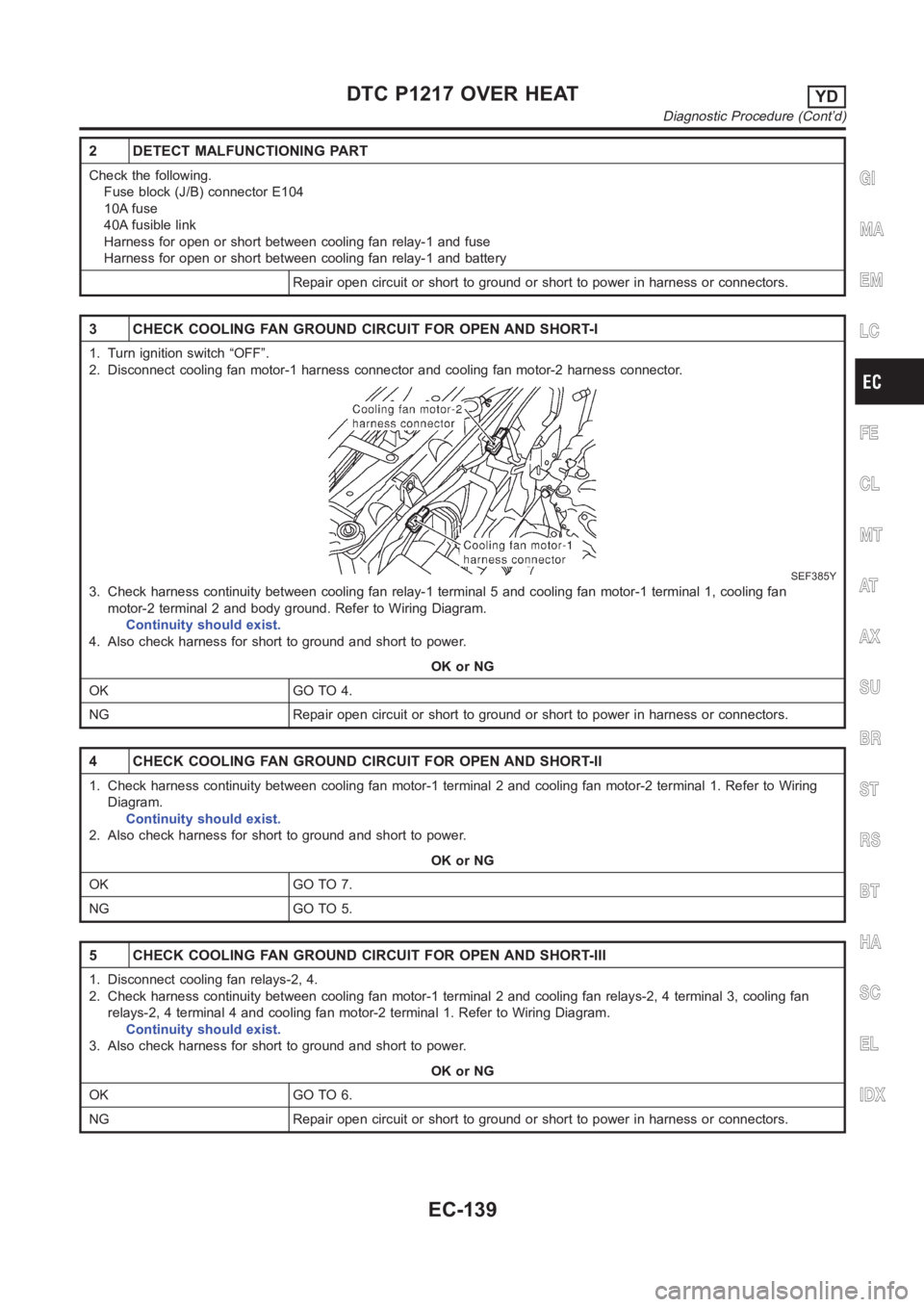
3 CHECK COOLING FAN GROUND CIRCUIT FOR OPEN AND SHORT-I
1. Turn ignition switch “OFF”.
2. Disconnect cooling fan motor-1 harness connector and cooling fan motor-2 harness connector.
SEF385Y
3. Check harness continuity between cooling fan relay-1 terminal 5 and cooling fan motor-1 terminal 1, cooling fan
motor-2 terminal 2 and body ground. Refer to Wiring Diagram.
Continuity should exist.
4. Also check harness for short to ground and short to power.
OK or NG
OK GO TO 4.
NG Repair open circuit or short to ground or short to power in harness or connectors.
4 CHECK COOLING FAN GROUND CIRCUIT FOR OPEN AND SHORT-II
1. Check harness continuity between cooling fan motor-1 terminal 2 and cooling fan motor-2 terminal 1. Refer to Wiring
Diagram.
Continuity should exist.
2. Also check harness for short to ground and short to power.
OK or NG
OK GO TO 7.
NG GO TO 5.
5 CHECK COOLING FAN GROUND CIRCUIT FOR OPEN AND SHORT-III
1. Disconnect cooling fan relays-2, 4.
2. Check harness continuity between cooling fan motor-1 terminal 2 and cooling fan relays-2, 4 terminal 3, cooling fan
relays-2, 4 terminal 4 and cooling fan motor-2 terminal 1. Refer to Wiring Diagram.
Continuity should exist.
3. Also check harness for short to ground and short to power.
OK or NG
OK GO TO 6.
NG Repair open circuit or short to ground or short to power in harness or connectors.
GI
MA
EM
LC
FE
CL
MT
AT
AX
SU
BR
ST
RS
BT
HA
SC
EL
IDX
DTC P1217 OVER HEATYD
Diagnostic Procedure (Cont’d)
EC-139
Page 1194 of 3189
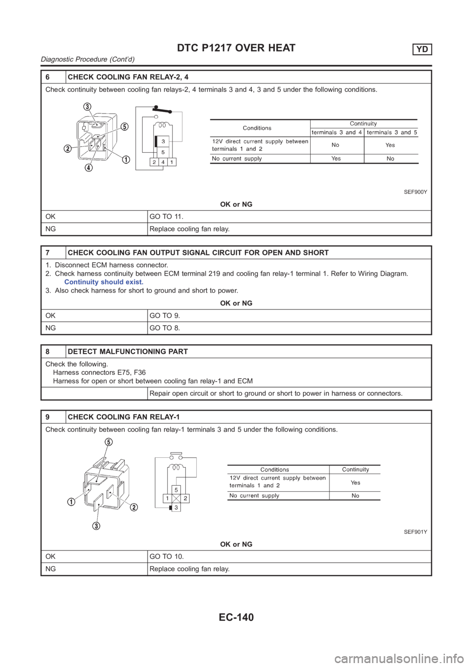
6 CHECK COOLING FAN RELAY-2, 4
Check continuity between cooling fan relays-2, 4 terminals 3 and 4, 3 and 5 under the following conditions.
SEF900Y
OK or NG
OK GO TO 11.
NG Replace cooling fan relay.
7 CHECK COOLING FAN OUTPUT SIGNAL CIRCUIT FOR OPEN AND SHORT
1. Disconnect ECM harness connector.
2. Check harness continuity between ECM terminal 219 and cooling fan relay-1 terminal 1. Refer to Wiring Diagram.
Continuity should exist.
3. Also check harness for short to ground and short to power.
OK or NG
OK GO TO 9.
NG GO TO 8.
8 DETECT MALFUNCTIONING PART
Check the following.
Harness connectors E75, F36
Harness for open or short between cooling fan relay-1 and ECM
Repair open circuit or short to ground or short to power in harness or connectors.
9 CHECK COOLING FAN RELAY-1
Check continuity between cooling fan relay-1 terminals 3 and 5 under the following conditions.
SEF901Y
OK or NG
OK GO TO 10.
NG Replace cooling fan relay.
DTC P1217 OVER HEATYD
Diagnostic Procedure (Cont’d)
EC-140
Page 1196 of 3189
2 DETECT MALFUNCTIONING PART
Check the following.
30A fusible link
10A fuse
Harness for open or short between cooling fan relays-2, 3, 4 and fuse
Harness for open or short between cooling fan relay-3 and fusible link
Repair harness or connectors.
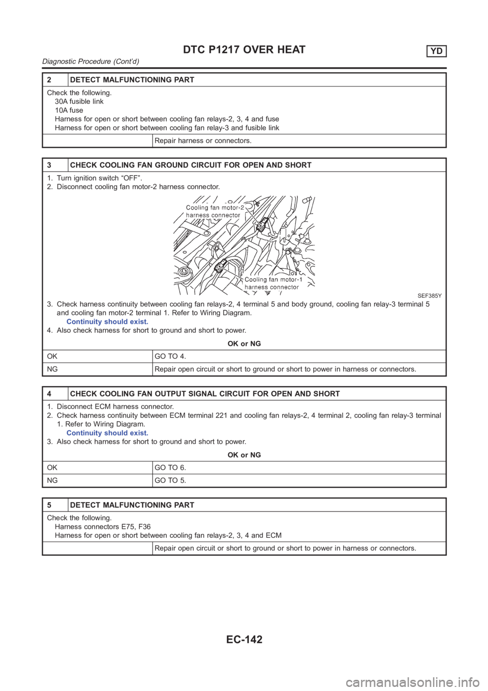
3 CHECK COOLING FAN GROUND CIRCUIT FOR OPEN AND SHORT
1. Turn ignition switch “OFF”.
2. Disconnect cooling fan motor-2 harness connector.
SEF385Y
3. Check harness continuity between cooling fan relays-2, 4 terminal 5 andbody ground, cooling fan relay-3 terminal 5
and cooling fan motor-2 terminal 1. Refer to Wiring Diagram.
Continuity should exist.
4. Also check harness for short to ground and short to power.
OK or NG
OK GO TO 4.
NG Repair open circuit or short to ground or short to power in harness or connectors.
4 CHECK COOLING FAN OUTPUT SIGNAL CIRCUIT FOR OPEN AND SHORT
1. Disconnect ECM harness connector.
2. Check harness continuity between ECM terminal 221 and cooling fan relays-2, 4 terminal 2, cooling fan relay-3 terminal
1. Refer to Wiring Diagram.
Continuity should exist.
3. Also check harness for short to ground and short to power.
OK or NG
OK GO TO 6.
NG GO TO 5.
5 DETECT MALFUNCTIONING PART
Check the following.
Harness connectors E75, F36
Harness for open or short between cooling fan relays-2, 3, 4 and ECM
Repair open circuit or short to ground or short to power in harness or connectors.
DTC P1217 OVER HEATYD
Diagnostic Procedure (Cont’d)
EC-142
Page 2935 of 3189
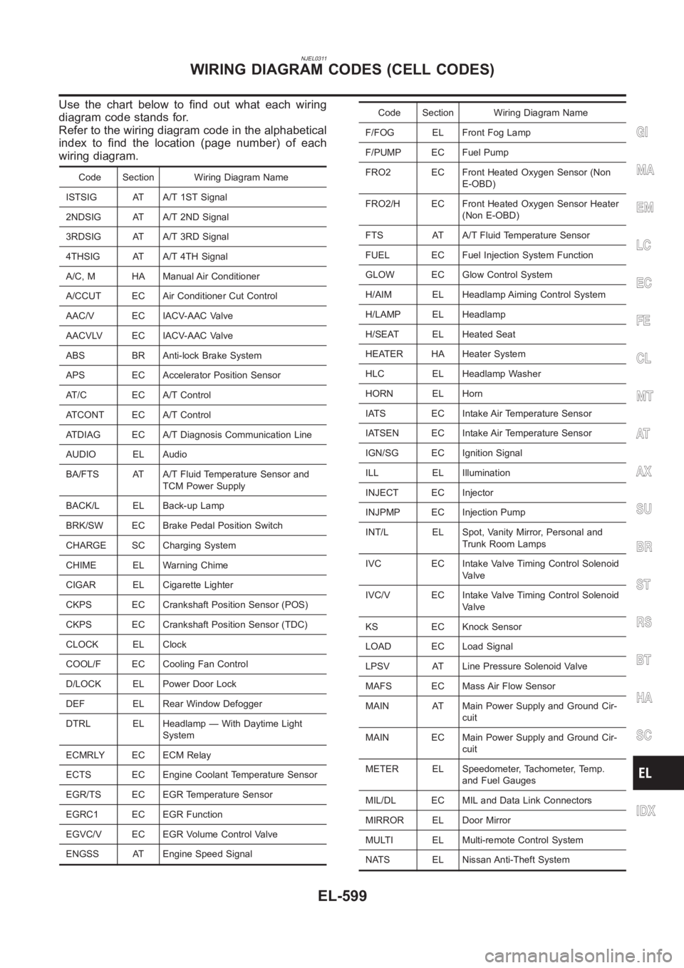
NJEL0311
Use the chart below to find out what each wiring
diagram code stands for.
Refer to the wiring diagram code in the alphabetical
index to find the location (page number) of each
wiring diagram.
Code Section Wiring Diagram Name
ISTSIG AT A/T 1ST Signal
2NDSIG AT A/T 2ND Signal
3RDSIG AT A/T 3RD Signal
4THSIG AT A/T 4TH Signal
A/C, M HA Manual Air Conditioner
A/CCUT EC Air Conditioner Cut Control
AAC/V EC IACV-AAC Valve
AACVLV EC IACV-AAC Valve
ABS BR Anti-lock Brake System
APS EC Accelerator Position Sensor
AT/C EC A/T Control
ATCONT EC A/T Control
ATDIAG EC A/T Diagnosis Communication Line
AUDIO EL Audio
BA/FTS AT A/T Fluid Temperature Sensor and
TCM Power Supply
BACK/L EL Back-up Lamp
BRK/SW EC Brake Pedal Position Switch
CHARGE SC Charging System
CHIME EL Warning Chime
CIGAR EL Cigarette Lighter
CKPS EC Crankshaft Position Sensor (POS)
CKPS EC Crankshaft Position Sensor (TDC)
CLOCK EL Clock
COOL/F EC Cooling Fan Control
D/LOCK EL Power Door Lock
DEF EL Rear Window Defogger
DTRL EL Headlamp — With Daytime Light
System
ECMRLY EC ECM Relay
ECTS EC Engine Coolant Temperature Sensor
EGR/TS EC EGR Temperature Sensor
EGRC1 EC EGR Function
EGVC/V EC EGR Volume Control Valve
ENGSS AT Engine Speed Signal
Code Section Wiring Diagram Name
F/FOG EL Front Fog Lamp
F/PUMP EC Fuel Pump
FRO2 EC Front Heated Oxygen Sensor (Non
E-OBD)
FRO2/H EC Front Heated Oxygen Sensor Heater
(Non E-OBD)
FTS AT A/T Fluid Temperature Sensor
FUEL EC Fuel Injection System Function
GLOW EC Glow Control System
H/AIM EL Headlamp Aiming Control System
H/LAMP EL Headlamp
H/SEAT EL Heated Seat
HEATER HA Heater System
HLC EL Headlamp Washer
HORN EL Horn
IATS EC Intake Air Temperature Sensor
IATSEN EC Intake Air Temperature Sensor
IGN/SG EC Ignition Signal
ILL EL Illumination
INJECT EC Injector
INJPMP EC Injection Pump
INT/L EL Spot, Vanity Mirror, Personal and
Trunk Room Lamps
IVC EC Intake Valve Timing Control Solenoid
Valve
IVC/V EC Intake Valve Timing Control Solenoid
Valve
KS EC Knock Sensor
LOAD EC Load Signal
LPSV AT Line Pressure Solenoid Valve
MAFS EC Mass Air Flow Sensor
MAIN AT Main Power Supply and Ground Cir-
cuit
MAIN EC Main Power Supply and Ground Cir-
cuit
METER EL Speedometer, Tachometer, Temp.
and Fuel Gauges
MIL/DL EC MIL and Data Link Connectors
MIRROR EL Door Mirror
MULTI EL Multi-remote Control System
NATS EL Nissan Anti-Theft System
GI
MA
EM
LC
EC
FE
CL
MT
AT
AX
SU
BR
ST
RS
BT
HA
SC
IDX
WIRING DIAGRAM CODES (CELL CODES)
EL-599
Page 3178 of 3189
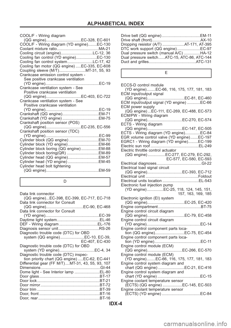
COOL/F - Wiring diagram
(QG engine)................................EC-328, EC-601
COOL/F - Wiring diagram (YD engine) ........EC-130
Coolant mixture ratio......................................MA-21
Cooling circuit (engine).............................LC-12, 36
Cooling fan control (YD engine)...................EC-130
Cooling fan control system .......................LC-17, 42
Cooling fan motor (QG engine) .....EC-335, EC-608
Coupling sleeve (M/T)........................MT-31, 55, 93
Crankcase emission control system -
See positive crankcase ventilation
(YD engine).................................................EC-19
Crankcase ventilation system - See
Positive crankcase ventilation
(QG engine)................................EC-403, EC-722
Crankcase ventilation system - See
Positive crankcase ventilation
(YD engine).................................................EC-19
Crankshaft (QG engine).................................EM-71
Crankshaft (YD engine) .................................EM-75
Crankshaft position sensor (POS)
(QG engine)................................EC-235, EC-556
Crankshaft position sensor (TDC)
(YD engine).................................................EC-99
Cylinder block (QG engine) ...........................EM-70
Cylinder block (YD engine) ............................EM-66
Cylinder block boring (QG engine) ................EM-88
Cylinder block boring(QR) .............................EM-89
Cylinder head (QG engine)............................EM-57
Cylinder head (YD engine) ............................EM-45
Cylinder head bolt tightening
(QG engine)................................................EM-59
D
Data link connector
(QG engine) ...EC-398, EC-399, EC-717, EC-718
Data link connector for Consult
(QG engine)..................................EC-90, EC-468
Data link connector for Consult
(YD engine).................................................EC-39
Daytime light system.......................................EL-46
DEF - Wiring diagram ...................................EL-176
Diagnosis sensor unit .....................................RS-26
Diagnostic trouble code (DTC) for OBD
system (QG engine) ......................EC-10, EC-39,
EC-407, EC-430
Diagnostic trouble code (DTC) for OBD
system (YD engine) ................................EC-4, 34
Diagnostic trouble code (DTC) inspec-
tion priority chart (QG engine) .....EC-62, EC-441
Differential gear (FF M/T) ....MT-31, 43, 55, 93, 107
Dimensions <0011001100110011001100110011001100110011001100110011001100110011001100110011001100110011001100110011001100110011001100110011001100110011001100110011001100110011001100110011001100110011001100110011001100
1100110011[.GI-44
Dome light - See Interior lamp .......................EL-80
Door glass <0011001100110011001100110011001100110011001100110011001100110011001100110011001100110011001100110011001100110011001100110011001100110011001100110011001100110011001100110011001100110011001100110011001100
11001100110011[.BT-17
Door lock <0011001100110011001100110011001100110011001100110011001100110011001100110011001100110011001100110011001100110011001100110011001100110011001100110011001100110011001100110011001100110011001100110011001100
110011001100110011[..BT-21
Door mirror <0011001100110011001100110011001100110011001100110011001100110011001100110011001100110011001100110011001100110011001100110011001100110011001100110011001100110011001100110011001100110011001100110011001100
1100110011[.BT-72
Door trim <0011001100110011001100110011001100110011001100110011001100110011001100110011001100110011001100110011001100110011001100110011001100110011001100110011001100110011001100110011001100110011001100110011001100
110011001100110011[..BT-39
Door, front <0011001100110011001100110011001100110011001100110011001100110011001100110011001100110011001100110011001100110011001100110011001100110011001100110011001100110011001100110011001100110011001100110011001100
1100110011[..BT-16
Door, rear <0011001100110011001100110011001100110011001100110011001100110011001100110011001100110011001100110011001100110011001100110011001100110011001100110011001100110011001100110011001100110011001100110011001100
11001100110011[..BT-16Drive belt (QG engine) ...................................EM-11
Drive shaft (front)............................................AX-10
Dropping resistor (A/T) ....................AT-171, AT-395
DTC work support (QG engine) .....................EC-97
Dual pressure switch (manual A/C) ...............HA-12
Dual pressure switch ......ATC-15, ATC-86, ATC-144
Duct and grilles...........................................ATC-131
E
ECCS-D control module
(YD engine) ........EC-66, 116, 175, 177, 181, 183
ECM input/output signal
(QG engine)..................................EC-81, EC-460
ECM input/output signal (YD engine) ............EC-66
ECM power supply
(QG engine) ...EC-111, EC-269, EC-488, EC-573
ECM/PW - Wiring diagram
(QG engine)................................EC-270, EC-574
ECTS - Wiring diagram
(QG engine)................................EC-147, EC-505
ECTS - Wiring diagram (YD engine)..............EC-84
EGR volume control valve (YD engine) .......EC-197
EGRC1 - Wiring diagram (YD engine) .........EC-199
Electric sun roof ............................................EL-249
Electric throttle control actuator
(QG engine) ................EC-277, EC-279, EC-292,
EC-577, EC-580, EC-593
Electrical diagnoses.........................................GI-22
Electrical load signal circuit
(QG engine)................................EC-393, EC-712
Electrical unit ................................................Foldout
Electrical units location .................................EL-543
Electronic fuel injection pump
(YD engine) ...............EC-25, 118, 124, 145, 151,
157, 163, 169, 185
Electronic ignition (EI) system
(QG engine)..................................EC-25, EC-420
Engine compartment .......................................BT-75
Engine control circuit diagram
(QG engine)..................................EC-79, EC-458
Engine control circuit diagram
(YD engine).................................................EC-14
Engine control component parts loca-
tion (QG engine)...........................EC-75, EC-454
Engine control component parts loca-
tion (YD engine) ..........................................EC-11
Engine control module (ECM)
(QG engine)................................EC-266, EC-570
Engine control module (ECM)
(YD engine) ........EC-66, 116, 175, 177, 181, 183
Engine control system diagram and
chart (QG engine) ........................EC-21, EC-416
Engine control system diagram and
chart (YD engine) .......................................EC-15
Engine coolant temperature sensor
(ECTS) (QG engine) ..................EC-145, EC-503
Engine coolant temperature sensor
(ECTS) (YD engine) ...................................EC-84
ALPHABETICAL INDEX
IDX-4