immobilizer NISSAN ALMERA N16 2003 Electronic Repair Manual
[x] Cancel search | Manufacturer: NISSAN, Model Year: 2003, Model line: ALMERA N16, Model: NISSAN ALMERA N16 2003Pages: 3189, PDF Size: 54.76 MB
Page 2529 of 3189

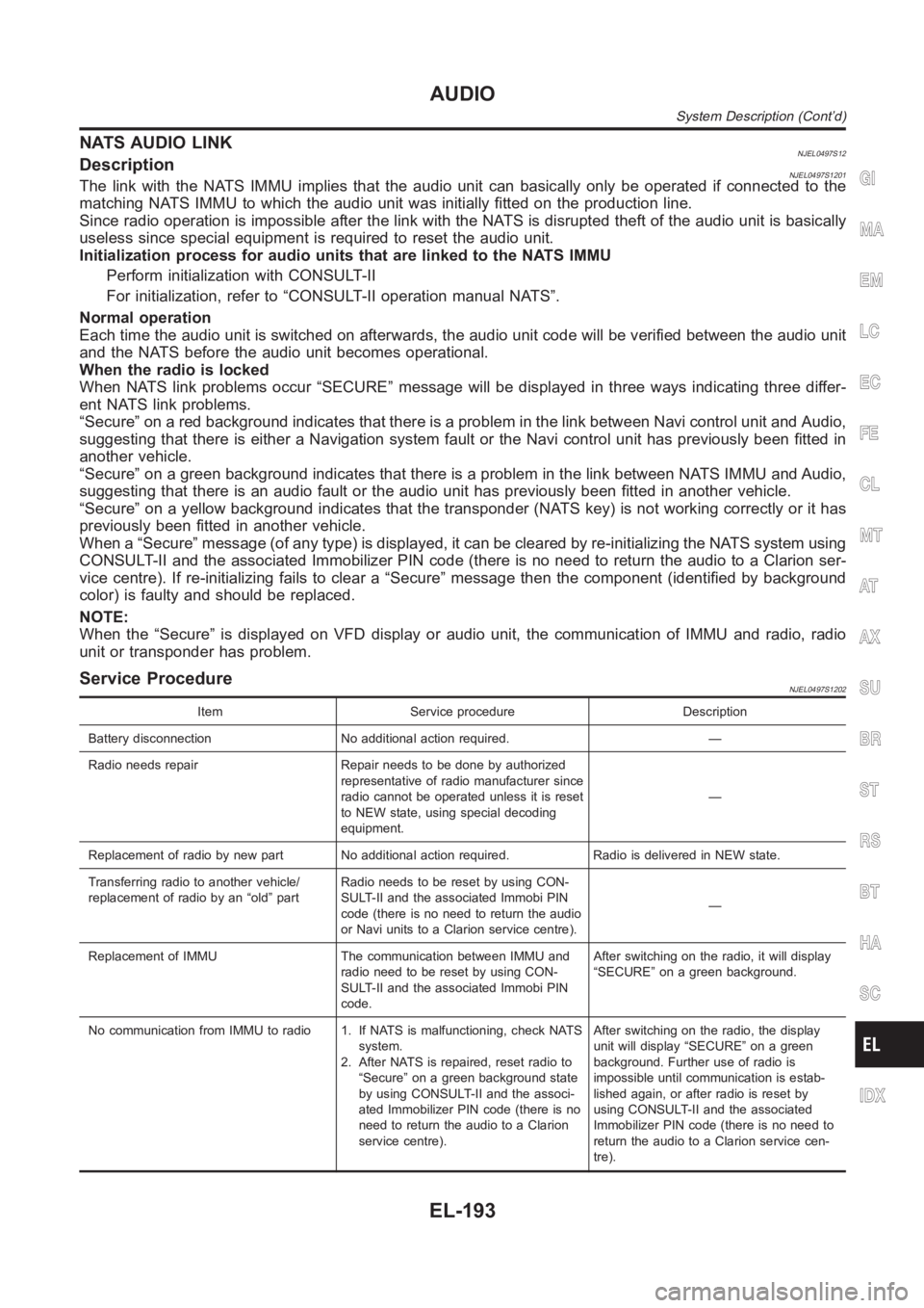
NATS AUDIO LINKNJEL0497S12DescriptionNJEL0497S1201The link with the NATS IMMU implies that the audio unit can basically only beoperated if connected to the
matching NATS IMMU to which the audio unit was initially fitted on the production line.
Since radio operation is impossible after the link with the NATS is disrupted theft of the audio unit is basically
useless since special equipment is required to reset the audio unit.
Initialization process for audio units that are linked to the NATS IMMU
Perform initialization with CONSULT-II
For initialization, refer to “CONSULT-II operation manual NATS”.
Normal operation
Each time the audio unit is switched on afterwards, the audio unit code willbe verified between the audio unit
and the NATS before the audio unit becomes operational.
When the radio is locked
When NATS link problems occur “SECURE” message will be displayed in three ways indicating three differ-
ent NATS link problems.
“Secure” on a red background indicates that there is a problem in the link between Navi control unit and Audio,
suggesting that there is either a Navigation system fault or the Navi control unit has previously been fitted in
another vehicle.
“Secure” on a green background indicates that there is a problem in the linkbetween NATS IMMU and Audio,
suggesting that there is an audio fault or the audio unit has previously been fitted in another vehicle.
“Secure” on a yellow background indicates that the transponder (NATS key)is not working correctly or it has
previously been fitted in another vehicle.
When a “Secure” message (of any type) is displayed, it can be cleared by re-initializing the NATS system using
CONSULT-II and the associated Immobilizer PIN code (there is no need to return the audio to a Clarion ser-
vice centre). If re-initializing fails to clear a “Secure” message then the component (identified by background
color) is faulty and should be replaced.
NOTE:
When the “Secure” is displayed on VFD display or audio unit, the communication of IMMU and radio, radio
unit or transponder has problem.
Service ProcedureNJEL0497S1202
Item Service procedure Description
Battery disconnection No additional action required. —
Radio needs repair Repair needs to be done by authorized
representative of radio manufacturer since
radio cannot be operated unless it is reset
to NEW state, using special decoding
equipment.—
Replacement of radio by new part No additional action required. Radio is delivered in NEW state.
Transferring radio to another vehicle/
replacement of radio by an “old” partRadio needs to be reset by using CON-
SULT-II and the associated Immobi PIN
code (there is no need to return the audio
or Navi units to a Clarion service centre).—
Replacement of IMMU The communication between IMMU and
radio need to be reset by using CON-
SULT-II and the associated Immobi PIN
code.After switching on the radio, it will display
“SECURE” on a green background.
No communication from IMMU to radio 1. If NATS is malfunctioning, check NATS
system.
2. After NATS is repaired, reset radio to
“Secure” on a green background state
by using CONSULT-II and the associ-
ated Immobilizer PIN code (there is no
need to return the audio to a Clarion
service centre).After switching on the radio, the display
unit will display “SECURE” on a green
background. Further use of radio is
impossible until communication is estab-
lished again, or after radio is reset by
using CONSULT-II and the associated
Immobilizer PIN code (there is no need to
return the audio to a Clarion service cen-
tre).
GI
MA
EM
LC
EC
FE
CL
MT
AT
AX
SU
BR
ST
RS
BT
HA
SC
IDX
AUDIO
System Description (Cont’d)
EL-193
Page 2722 of 3189

Component Parts and Harness Connetor
Location
NJEL0406For details, refer to “ELECTRICAL UNIT LOCATION” (EL-543) and
“HARNESS LAYOUT” (EL-550).
System DescriptionNJEL0407NATS (Nissan Anti-Theft System) has the following immobilizer functions:
Since only NATS ignition keys, whose ID nos. have been registered into the ECM and IMMU of NATS,
allow the engine to run, operation of a stolen vehicle without a NATS registered key is prevented by NATS.
That is to say, NATS will immobilize the engine if someone tries to start it without the registered key of
NATS.
This version of NATS has dongle unit to improve its anti-theft performance(RHD models for Europe).
Dongle unit has its own ID which is registered into NATS IMMU. So if dongle unit is replaced, initialization
must be carried out.
When malfunction of dongle unit is detected:
The security indicator lamp illuminates for about 15 minutes after ignition switch is turned to ON.
− When dongle unit has a malfunction and the indicator lamp is illuminated,engine can not be started.
However engine can be started only one time when security indicator lamp turns off in about 15 minutes
after ignition switch is turned to ON.
All of the originally supplied ignition key IDs have been NATS registered.
If requested by the vehicle owner, a maximum of five key IDs can be registered into the NATS compo-
nents.
The security indicator blinks when the ignition switch is in “OFF” or “ACC”position. Therefore, NATS warns
outsiders that the vehicle is equipped with the anti-theft system.
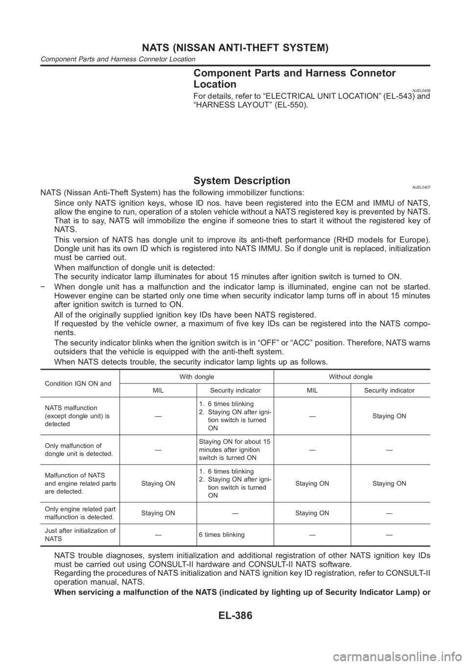
When NATS detects trouble, the security indicator lamp lights up as follows.
Condition IGN ON andWith dongle Without dongle
MIL Security indicator MIL Security indicator
NATS malfunction
(except dongle unit) is
detected—1. 6 times blinking
2. Staying ON after igni-
tion switch is turned
ON— Staying ON
Only malfunction of
dongle unit is detected.—Staying ON for about 15
minutes after ignition
switch is turned ON——
Malfunction of NATS
and engine related parts
are detected.Staying ON1. 6 times blinking
2. Staying ON after igni-
tion switch is turned
ONStaying ON Staying ON
Only engine related part
malfunction is detected.Staying ON — Staying ON —
Just after initialization of
NATS— 6 times blinking — —
NATS trouble diagnoses, system initialization and additional registration of other NATS ignition key IDs
must be carried out using CONSULT-II hardware and CONSULT-II NATS software.
Regarding the procedures of NATS initialization and NATS ignition key ID registration, refer to CONSULT-II
operation manual, NATS.
When servicing a malfunction of the NATS (indicated by lighting up of Security Indicator Lamp) or
NATS (NISSAN ANTI-THEFT SYSTEM)
Component Parts and Harness Connetor Location
EL-386
Page 2723 of 3189

registering another NATS ignition key ID no., it may be necessary to re-register original key iden-
tification. Therefore, be sure to receive ALL KEYS from vehicle owner.
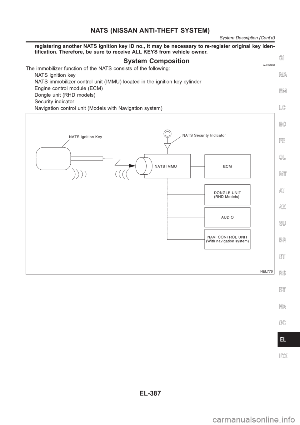
System CompositionNJEL0408The immobilizer function of the NATS consists of the following:
NATS ignition key
NATS immobilizer control unit (IMMU) located in the ignition key cylinder
Engine control module (ECM)
Dongle unit (RHD models)
Security indicator
Navigation control unit (Models with Navigation system)
NEL776
GI
MA
EM
LC
EC
FE
CL
MT
AT
AX
SU
BR
ST
RS
BT
HA
SC
IDX
NATS (NISSAN ANTI-THEFT SYSTEM)
System Description (Cont’d)
EL-387
Page 3181 of 3189

Lubricants<0011001100110011001100110011001100110011001100110011001100110011001100110011001100110011001100110011001100110011001100110011001100110011001100110011001100110011001100110011001100110011001100110011001100
1100110011[..MA-19
Lubrication circuit (engine) .........................LC-4, 26
Lubrication oil A/C ......................................ATC-150
M
M/T major overhaul ............................MT-30, 54, 92
M/T oil replacement..................................MT-14, 15
M/T removal and installation ..........................MT-23
MAFS - Wiring diagram
(QG engine)................................EC-137, EC-499
MAFS - Wiring diagram (YD engine) .............EC-80
Magnet clutch (manual A/C)...........................HA-82
Magnet clutch ...............................ATC-75, ATC-139
MAIN - Wiring diagram
(QG engine) ................................EC-111, EC-488
MAIN - Wiring diagram (YD engine) ..............EC-72
Mainshaft (M/T)..........................MT-39, 69, 93, 103
Malfunction indicator (MI)
(QG engine) .....EC-49, EC-398, EC-433, EC-717
Malfunction indicator lamp (MIL)
(YD engine).................................................EC-35
Manual air conditioner - Wiring diagram
(manual A/C) ...............................................HA-25
Manual transaxle number ................................GI-43
Mass air flow sensor (MAFS)
(QG engine)................................EC-135, EC-497
Mass air flow sensor (MAFS)
(YD engine).................................................EC-78
Master cylinder (brake) ..................................BR-14
Master cylinder (clutch) ...................................CL-11
Meter <0011001100110011001100110011001100110011001100110011001100110011001100110011001100110011001100110011001100110011001100110011001100110011001100110011001100110011001100110011001100110011001100110011001100
110011001100110011001100110011[...EL-110
MIL/DL - Wiring diagram
(QG engine) ...EC-398, EC-399, EC-717, EC-718
MIL/DL - Wiring diagram (YD engine)..........EC-213
MIRROR - Wiring diagram............................EL-251
Mirror defogger .............................................EL-173
Mirror, door<0011001100110011001100110011001100110011001100110011001100110011001100110011001100110011001100110011001100110011001100110011001100110011001100110011001100110011001100110011001100110011001100110011001100
110011[..BT-72
Misfire (QG engine) ......................................EC-226
Mode door control linkage adjustment
(manual A/C) ...............................................HA-42
Mode door control linkage
adjustment ................................ATC-62, ATC-126
Mode door motor ..........................ATC-59, ATC-126
Model variation ................................................GI-39
Molding - See Exterior ....................................BT-47
Multi-remote control system..........................EL-352
Multiport fuel injection (MFI) system
(QG engine)..................................EC-23, EC-418
Multiport fuel injection precautions ....................GI-6
N
NATS (Nissan anti-theft system)
precautions <0011001100110011001100110011001100110011001100110011001100110011001100110011001100110011001100110011001100110011001100110011001100110011001100110011001100110011001100110011001100110011001100110011001100
110011[GI-3
NATS (Nissan anti-theft system)...................EL-386
NATS - Wiring diagram .................................EL-388
NVH troubleshooting (AX) ................................AX-3NVH troubleshooting (BR)................................BR-6
NVH troubleshooting (CL) ................................CL-4
NVH troubleshooting (EM) (QG engine)..........EM-9
NVH troubleshooting (M/T) ............................MT-13
NVH troubleshooting (ST).................................ST-5
NVH troubleshooting (SU)..............................SU-16
NVIS (Nissan vehicle immobilizer sys-
tem) precautions ............................................GI-3
O
Oil pan (engine) (QG engine) ........................EM-22
Oil pan (YD engine) .......................................EM-15
Oil pressure (engine) ..................................LC-5, 27
Oil pump (engine) .......................................LC-5, 27
Oil pump regulator valve (engine) ..............LC-7, 29
On board diagnostic system
(QG engine)..................................EC-36, EC-430
On board diagnostic system
(YD engine).................................................EC-34
Operating cylinder (clutch)..............................CL-14
Overdrive control switch ..................AT-243, AT-339
Overheat (QG engine) ...................EC-325, EC-598
Oversize piston (QG engine) .........................EM-88
P
Park/neutral position switch (A/T) .................AT-112
Park/neutral position switch (M/T)..................MT-21
Park/Neutral position switch
(QG engine)................................EC-357, EC-691
Park/Neutral position switch
(YD engine)...............................................EC-208
Parking brake control .....................................BR-43
Parking lamp <0011001100110011001100110011001100110011001100110011001100110011001100110011001100110011001100110011001100110011001100110011001100110011001100110011001100110011001100110011001100110011001100110011001100
110028[L-55
PCV (positive crankcase ventilation)
(QG engine)................................EC-403, EC-722
PCV (positive crankcase ventilation)
(YD engine).................................................EC-19
PGC/V - Wiring diagram (QG engine) .........EC-254
PHASE - Wiring diagram
(QG engine)................................EC-242, EC-565
Piston assembly (QG engine)........................EM-88
Piston assembly (YD engine) ........................EM-81
Piston pin inspection (QG engine).................EM-84
Piston pin inspection (YD engine) .................EM-71
Piston ring inspection (QG engine) ...............EM-85
Piston ring inspection (YD engine) ................EM-71
Piston to bore clearance
(QG engine) ...................................EM-88, EM-89
Piston to bore clearance (YD engine) ...........EM-73
PNP/SW - Wiring diagram (QG engine) ......EC-359
PNP/SW - Wiring diagram (YD engine) .......EC-208
PNPSW1 - Wiring diagram
(QG engine) ..............................................EC-692
POS - Wiring diagram
(QG engine)................................EC-236, EC-558
POWER - Wiring diagram...............................EL-14
GI
MA
EM
LC
EC
FE
CL
MT
AT
AX
SU
BR
ST
RS
BT
HA
SC
EL
ALPHABETICAL INDEX
IDX-7