boot NISSAN ALMERA N16 2003 Electronic Repair Manual
[x] Cancel search | Manufacturer: NISSAN, Model Year: 2003, Model line: ALMERA N16, Model: NISSAN ALMERA N16 2003Pages: 3189, PDF Size: 54.76 MB
Page 1341 of 3189
SMT143DC
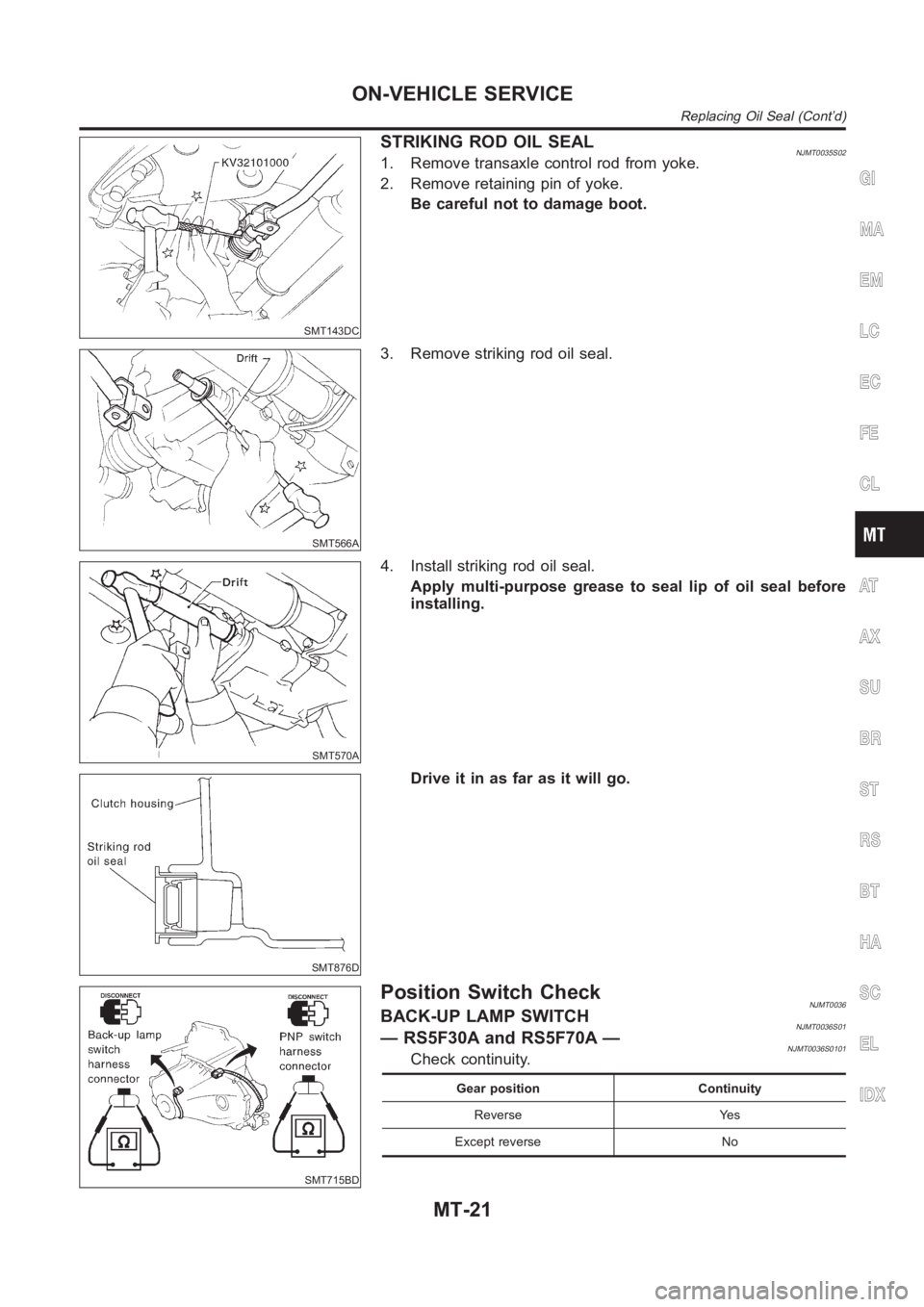
STRIKING ROD OIL SEALNJMT0035S021. Remove transaxle control rod from yoke.
2. Remove retaining pin of yoke.
Be careful not to damage boot.
SMT566A
3. Remove striking rod oil seal.
SMT570A
4. Install striking rod oil seal.
Apply multi-purpose grease to seal lip of oil seal before
installing.
SMT876D
Drive it in as far as it will go.
SMT715BD
Position Switch CheckNJMT0036BACK-UP LAMP SWITCHNJMT0036S01— RS5F30A and RS5F70A —NJMT0036S0101Check continuity.
Gear position Continuity
Reverse Yes
Except reverse No
GI
MA
EM
LC
EC
FE
CL
AT
AX
SU
BR
ST
RS
BT
HA
SC
EL
IDX
ON-VEHICLE SERVICE
Replacing Oil Seal (Cont’d)
MT-21
Page 1349 of 3189
NJMT0038
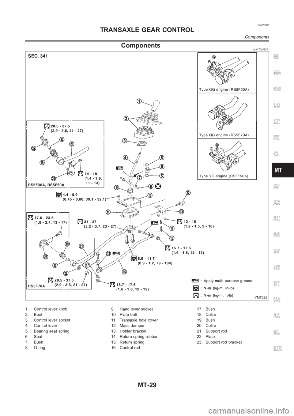
ComponentsNJMT0038S01
YMT028
1. Control lever knob
2. Boot
3. Control lever socket
4. Control lever
5. Bearing seat spring
6. Seat
7. Bush
8. O-ring9. Hand lever socket
10. Plate bolt
11. Transaxle hole cover
12. Mass damper
13. Holder bracket
14. Return spring rubber
15. Return spring
16. Control rod17. Bush
18. Collar
19. Bush
20. Collar
21. Support rod
22. Plate
23. Support rod bracket
GI
MA
EM
LC
EC
FE
CL
AT
AX
SU
BR
ST
RS
BT
HA
SC
EL
IDX
TRANSAXLE GEAR CONTROL
Components
MT-29
Page 1350 of 3189
NJMT0039
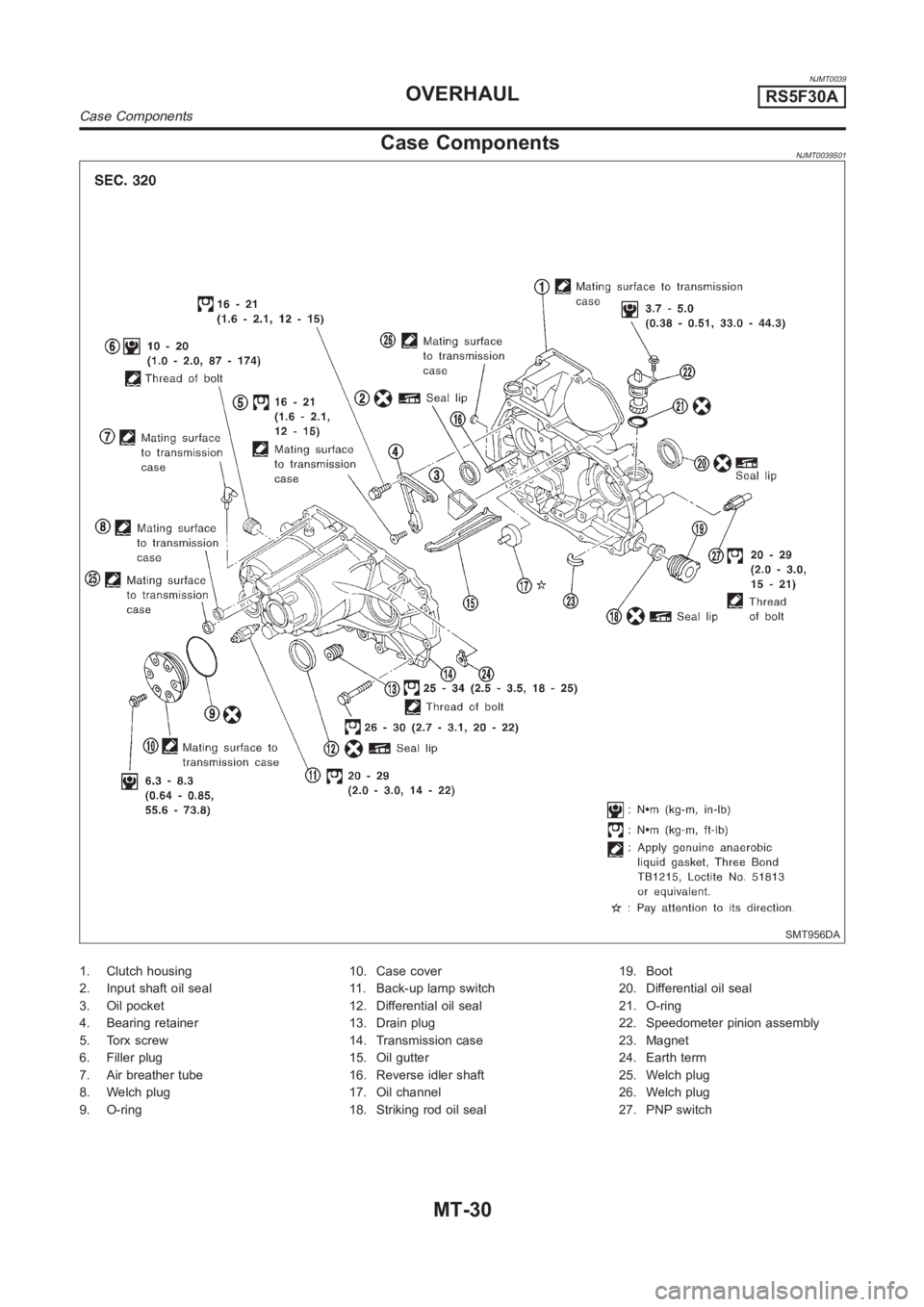
Case ComponentsNJMT0039S01
SMT956DA
1. Clutch housing
2. Input shaft oil seal
3. Oil pocket
4. Bearing retainer
5. Torx screw
6. Filler plug
7. Air breather tube
8. Welch plug
9. O-ring10. Case cover
11. Back-up lamp switch
12. Differential oil seal
13. Drain plug
14. Transmission case
15. Oil gutter
16. Reverse idler shaft
17. Oil channel
18. Striking rod oil seal19. Boot
20. Differential oil seal
21. O-ring
22. Speedometer pinion assembly
23. Magnet
24. Earth term
25. Welch plug
26. Welch plug
27. PNP switch
OVERHAULRS5F30A
Case Components
MT-30
Page 1374 of 3189
NJMT0054
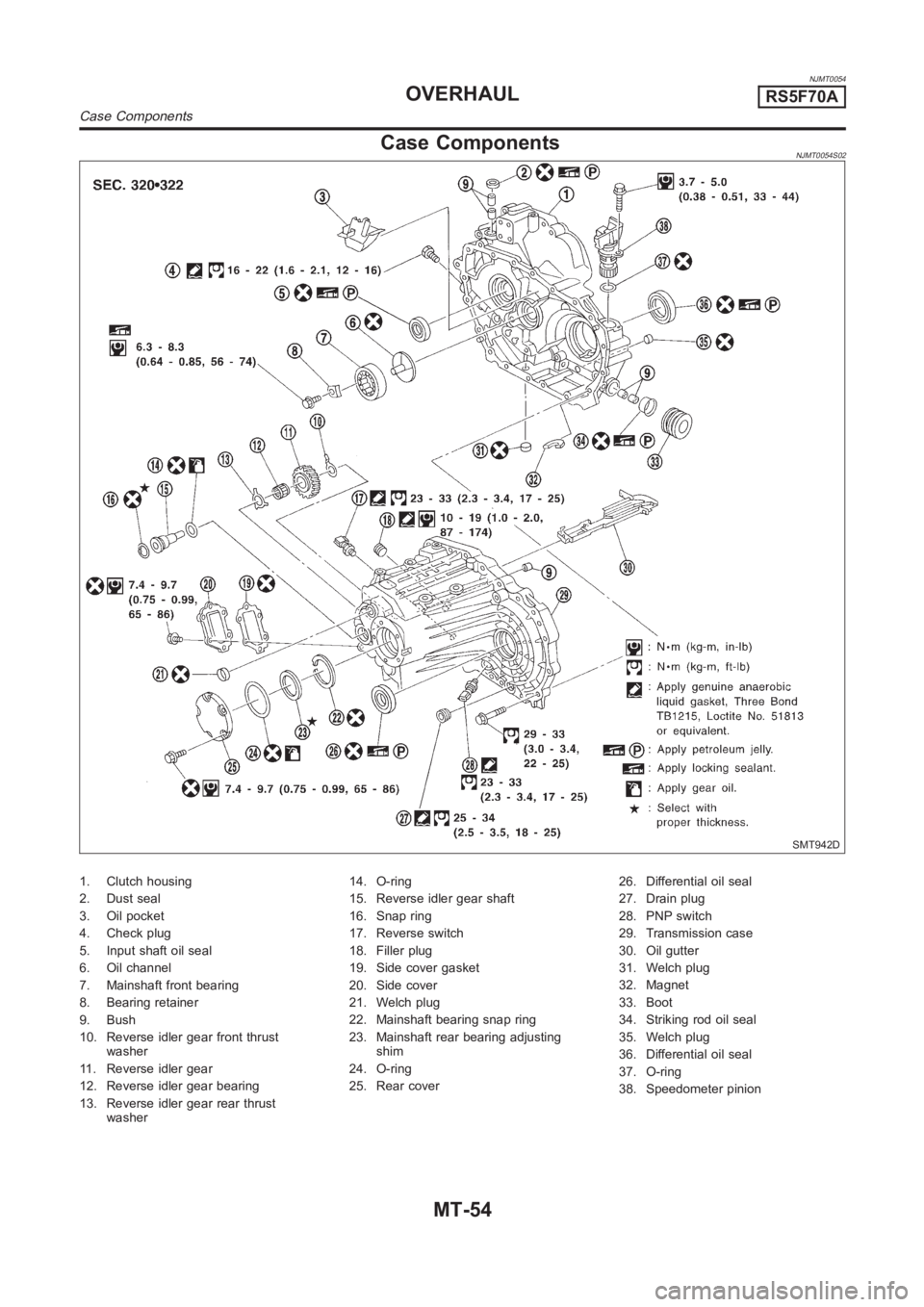
Case ComponentsNJMT0054S02
SMT942D
1. Clutch housing
2. Dust seal
3. Oil pocket
4. Check plug
5. Input shaft oil seal
6. Oil channel
7. Mainshaft front bearing
8. Bearing retainer
9. Bush
10. Reverse idler gear front thrust
washer
11. Reverse idler gear
12. Reverse idler gear bearing
13. Reverse idler gear rear thrust
washer14. O-ring
15. Reverse idler gear shaft
16. Snap ring
17. Reverse switch
18. Filler plug
19. Side cover gasket
20. Side cover
21. Welch plug
22. Mainshaft bearing snap ring
23. Mainshaft rear bearing adjusting
shim
24. O-ring
25. Rear cover26. Differential oil seal
27. Drain plug
28. PNP switch
29. Transmission case
30. Oil gutter
31. Welch plug
32. Magnet
33. Boot
34. Striking rod oil seal
35. Welch plug
36. Differential oil seal
37. O-ring
38. Speedometer pinion
OVERHAULRS5F70A
Case Components
MT-54
Page 1376 of 3189
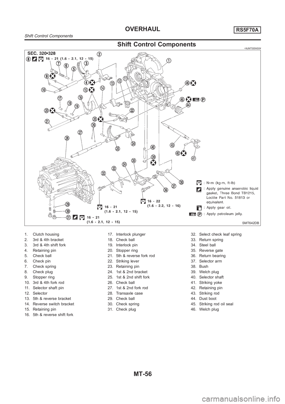
Shift Control Components=NJMT0054S04
SMT642DB
1. Clutch housing
2. 3rd & 4th bracket
3. 3rd & 4th shift fork
4. Retaining pin
5. Check ball
6. Check pin
7. Check spring
8. Check plug
9. Stopper ring
10. 3rd & 4th fork rod
11. Selector shaft pin
12. Selector
13. 5th & reverse bracket
14. Reverse switch bracket
15. Retaining pin
16. 5th & reverse shift fork17. Interlock plunger
18. Check ball
19. Interlock pin
20. Stopper ring
21. 5th & reverse fork rod
22. Striking lever
23. Retaining pin
24. 1st & 2nd bracket
25. 1st & 2nd shift fork
26. Check ball
27. 1st & 2nd fork rod
28. Transaxle case
29. Check ball
30. Check spring
31. Check plug32. Select check leaf spring
33. Return spring
34. Steel ball
35. Reverse gate
36. Return bearing
37. Selector arm
38. Bush
39. Welch plug
40. Selector shaft
41. Striking yoke
42. Retaining pin
43. Striking rod
44. Dust boot
45. Striking rod oil seal
46. Welch plug
OVERHAULRS5F70A
Shift Control Components
MT-56
Page 1403 of 3189
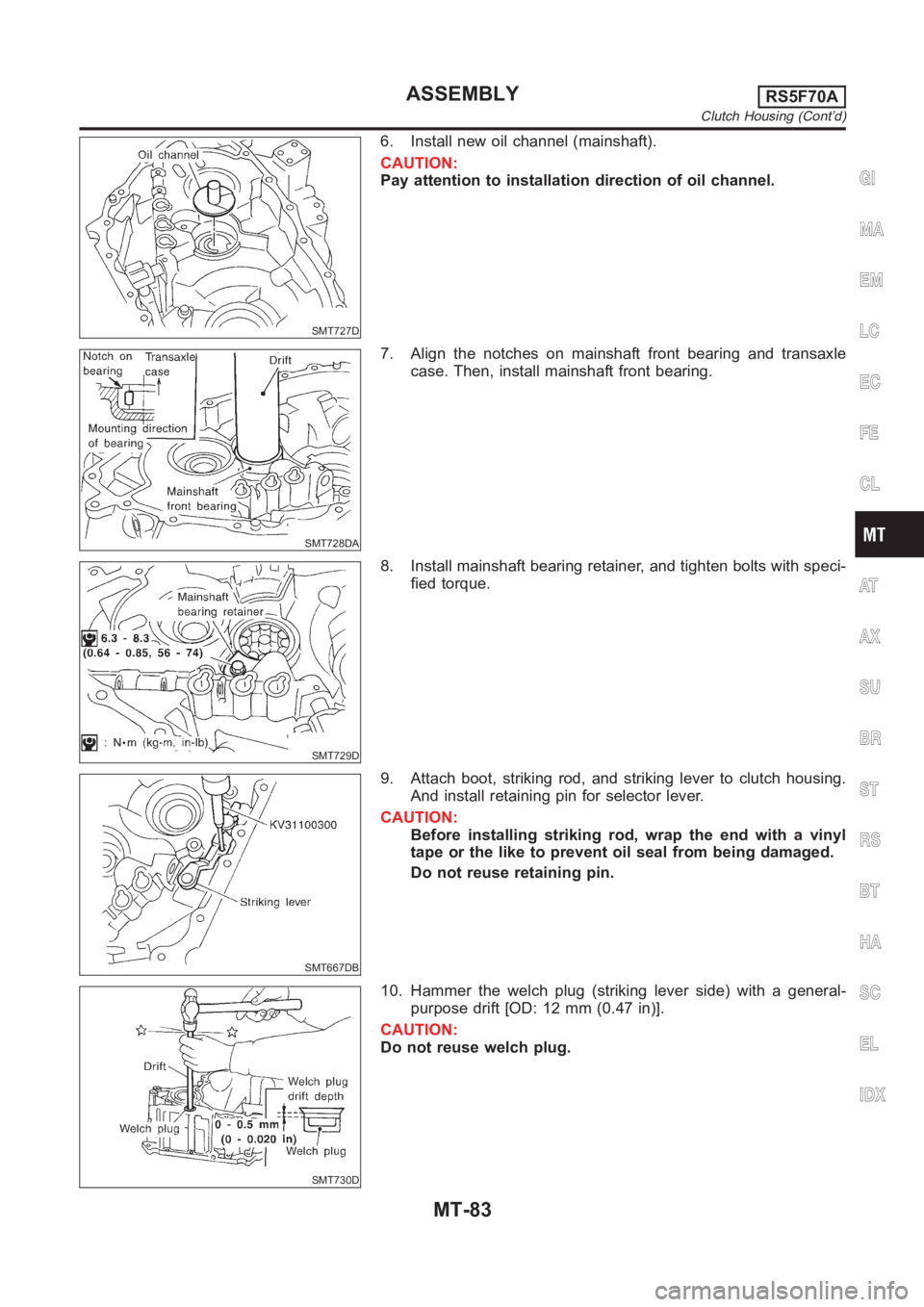
SMT727D
6. Install new oil channel (mainshaft).
CAUTION:
Pay attention to installation direction of oil channel.
SMT728DA
7. Align the notches on mainshaft front bearing and transaxle
case. Then, install mainshaft front bearing.
SMT729D
8. Install mainshaft bearing retainer, and tighten bolts with speci-
fied torque.
SMT667DB
9. Attach boot, striking rod, and striking lever to clutch housing.
And install retaining pin for selector lever.
CAUTION:
Before installing striking rod, wrap the end with a vinyl
tape or the like to prevent oil seal from being damaged.
Do not reuse retaining pin.
SMT730D
10. Hammer the welch plug (striking lever side) with a general-
purpose drift [OD: 12 mm (0.47 in)].
CAUTION:
Do not reuse welch plug.
GI
MA
EM
LC
EC
FE
CL
AT
AX
SU
BR
ST
RS
BT
HA
SC
EL
IDX
ASSEMBLYRS5F70A
Clutch Housing (Cont’d)
MT-83
Page 1412 of 3189
NJMT0009
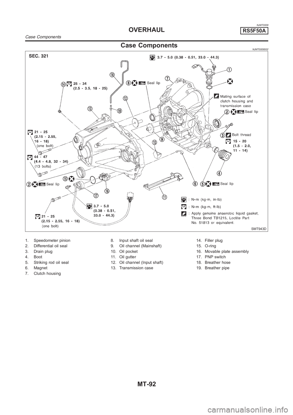
Case ComponentsNJMT0009S02
SMT943D
1. Speedometer pinion
2. Differential oil seal
3. Drain plug
4. Boot
5. Striking rod oil seal
6. Magnet
7. Clutch housing8. Input shaft oil seal
9. Oil channel (Mainshaft)
10. Oil pocket
11. Oil gutter
12. Oil channel (Input shaft)
13. Transmission case14. Filler plug
15. O-ring
16. Movable plate assembly
17. PNP switch
18. Breather hose
19. Breather pipe
OVERHAULRS5F50A
Case Components
MT-92
Page 2136 of 3189
SFA898A
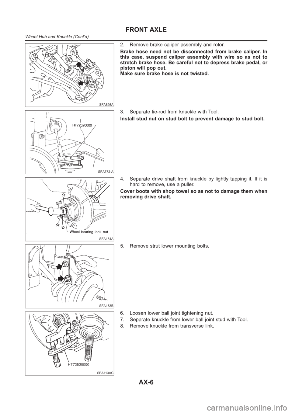
2. Remove brake caliper assembly and rotor.
Brake hose need not be disconnected from brake caliper. In
this case, suspend caliper assembly with wire so as not to
stretch brake hose. Be careful not to depress brake pedal, or
piston will pop out.
Make sure brake hose is not twisted.
SFA372-A
3. Separate tie-rod from knuckle with Tool.
Install stud nut on stud bolt to prevent damage to stud bolt.
SFA181A
4. Separate drive shaft from knuckle by lightly tapping it. If it is
hard to remove, use a puller.
Cover boots with shop towel so as not to damage them when
removing drive shaft.
SFA153B
5. Remove strut lower mounting bolts.
SFA113AC
6. Loosen lower ball joint tightening nut.
7. Separate knuckle from lower ball joint stud with Tool.
8. Remove knuckle from transverse link.
FRONT AXLE
Wheel Hub and Knuckle (Cont’d)
AX-6
Page 2140 of 3189
Drive Shaft
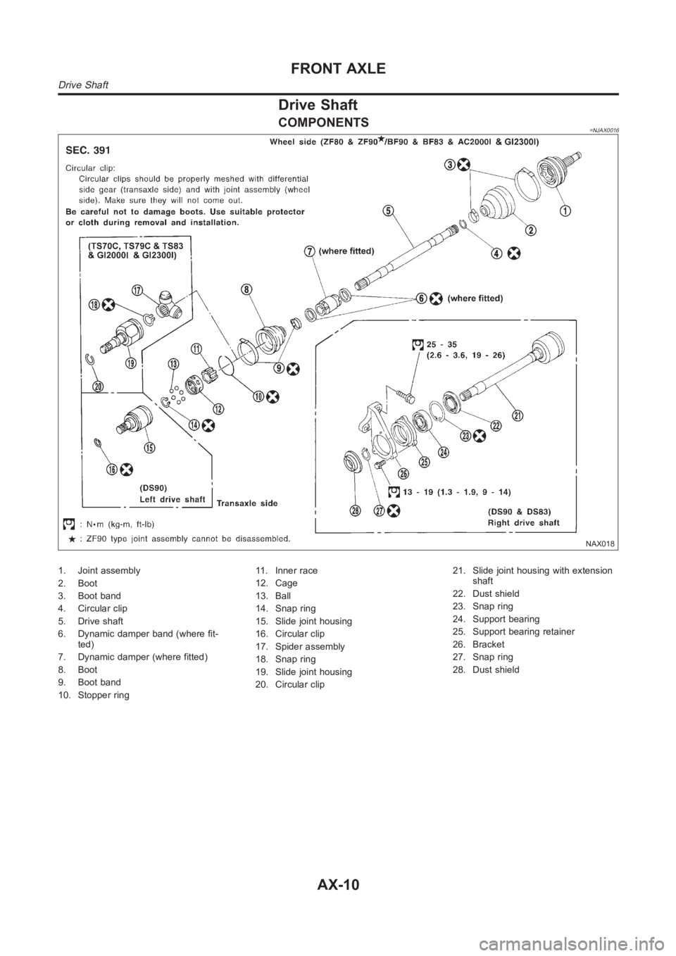
COMPONENTS=NJAX0016
NAX018
1. Joint assembly
2. Boot
3. Boot band
4. Circular clip
5. Drive shaft
6. Dynamic damper band (where fit-
ted)
7. Dynamic damper (where fitted)
8. Boot
9. Boot band
10. Stopper ring11. Inner race
12. Cage
13. Ball
14. Snap ring
15. Slide joint housing
16. Circular clip
17. Spider assembly
18. Snap ring
19. Slide joint housing
20. Circular clip21. Slide joint housing with extension
shaft
22. Dust shield
23. Snap ring
24. Support bearing
25. Support bearing retainer
26. Bracket
27. Snap ring
28. Dust shield
FRONT AXLE
Drive Shaft
AX-10
Page 2141 of 3189
SFA090A
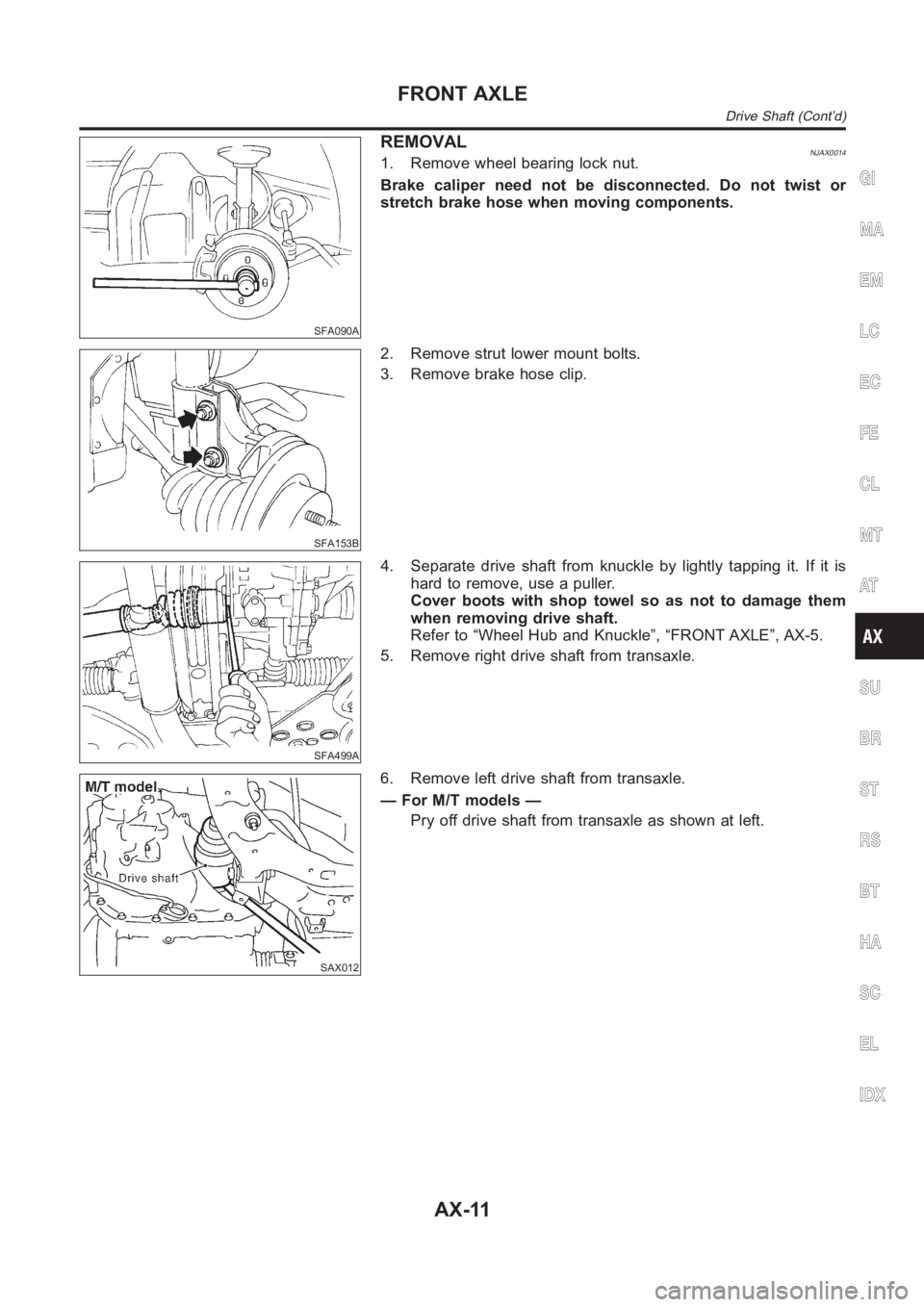
REMOVALNJAX00141. Remove wheel bearing lock nut.
Brake caliper need not be disconnected. Do not twist or
stretch brake hose when moving components.
SFA153B
2. Remove strut lower mount bolts.
3. Remove brake hose clip.
SFA499A
4. Separate drive shaft from knuckle by lightly tapping it. If it is
hard to remove, use a puller.
Cover boots with shop towel so as not to damage them
when removing drive shaft.
Refer to “Wheel Hub and Knuckle”, “FRONT AXLE”, AX-5.
5. Remove right drive shaft from transaxle.
SAX012
6. Remove left drive shaft from transaxle.
— For M/T models —
Pry off drive shaft from transaxle as shown at left.
GI
MA
EM
LC
EC
FE
CL
MT
AT
SU
BR
ST
RS
BT
HA
SC
EL
IDX
FRONT AXLE
Drive Shaft (Cont’d)
AX-11