open hood NISSAN ALMERA N16 2003 Electronic Repair Manual
[x] Cancel search | Manufacturer: NISSAN, Model Year: 2003, Model line: ALMERA N16, Model: NISSAN ALMERA N16 2003Pages: 3189, PDF Size: 54.76 MB
Page 59 of 3189
NJMA0004
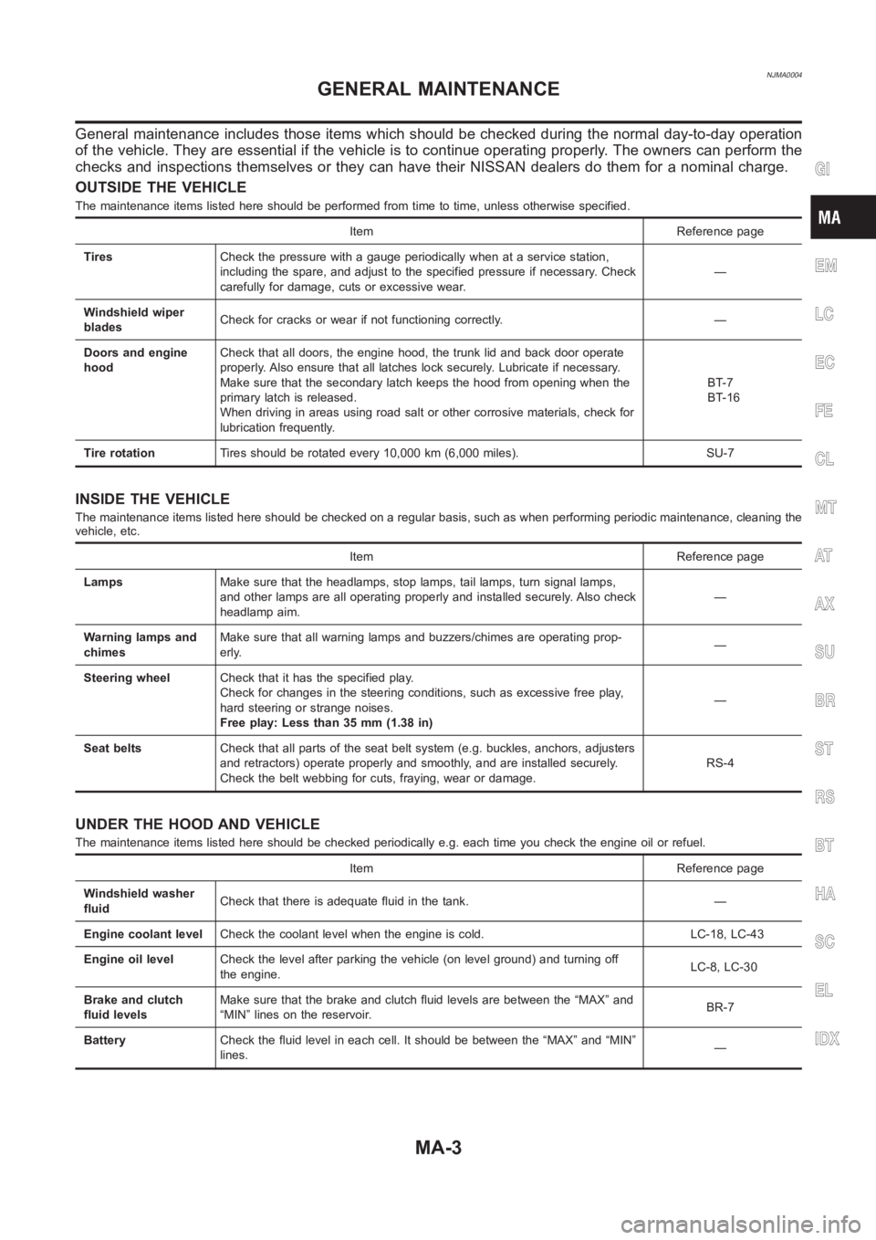
General maintenance includes those items which should be checked during the normal day-to-day operation
of the vehicle. They are essential if the vehicle is to continue operating properly. The owners can perform the
checks and inspections themselves or they can have their NISSAN dealers dothem for a nominal charge.
OUTSIDE THE VEHICLE
The maintenance items listed here should be performed from time to time, unless otherwise specified.
Item Reference page
TiresCheck the pressure with a gauge periodically when at a service station,
including the spare, and adjust to the specified pressure if necessary. Check
carefully for damage, cuts or excessive wear.—
Windshield wiper
bladesCheck for cracks or wear if not functioning correctly. —
Doors and engine
hoodCheck that all doors, the engine hood, the trunk lid and back door operate
properly. Also ensure that all latches lock securely. Lubricate if necessary.
Make sure that the secondary latch keeps the hood from opening when the
primary latch is released.
When driving in areas using road salt or other corrosive materials, check for
lubrication frequently.BT-7
BT-16
Tire rotationTires should be rotated every 10,000 km (6,000 miles). SU-7
INSIDE THE VEHICLE
The maintenance items listed here should be checked on a regular basis, such as when performing periodic maintenance, cleaning the
vehicle, etc.
Item Reference page
LampsMake sure that the headlamps, stop lamps, tail lamps, turn signal lamps,
and other lamps are all operating properly and installed securely. Also check
headlamp aim.—
Warning lamps and
chimesMake sure that all warning lamps and buzzers/chimes are operating prop-
erly.—
Steering wheelCheck that it has the specified play.
Check for changes in the steering conditions, such as excessive free play,
hard steering or strange noises.
Free play: Less than 35 mm (1.38 in)—
Seat beltsCheck that all parts of the seat belt system (e.g. buckles, anchors, adjusters
and retractors) operate properly and smoothly, and are installed securely.
Check the belt webbing for cuts, fraying, wear or damage.RS-4
UNDER THE HOOD AND VEHICLE
The maintenance items listed here should be checked periodically e.g. each time you check the engine oil or refuel.
Item Reference page
Windshield washer
fluidCheck that there is adequate fluid in the tank. —
Engine coolant levelCheck the coolant level when the engine is cold. LC-18, LC-43
Engine oil levelCheck the level after parking the vehicle (on level ground) and turning off
the engine.LC-8, LC-30
Brake and clutch
fluid levelsMake sure that the brake and clutch fluid levels are between the “MAX” and
“MIN” lines on the reservoir.BR-7
BatteryCheck the fluid level in each cell. It should be between the “MAX” and “MIN”
lines.—
GI
EM
LC
EC
FE
CL
MT
AT
AX
SU
BR
ST
RS
BT
HA
SC
EL
IDX
GENERAL MAINTENANCE
MA-3
Page 248 of 3189
crankshaft position sensor (TDC sensor) from the assem-
bly.
Always pay extra attention not to damage edge of crank-
shaft position sensor (TDC sensor) or ring gear teeth.
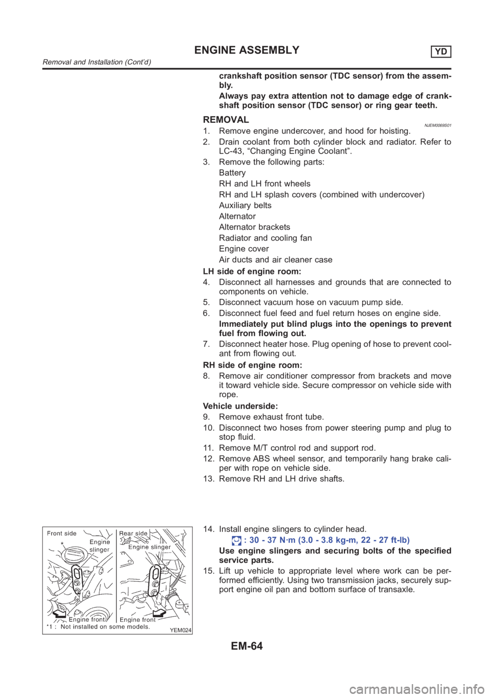
REMOVALNJEM0069S011. Remove engine undercover, and hood for hoisting.
2. Drain coolant from both cylinder block and radiator. Refer to
LC-43, “Changing Engine Coolant”.
3. Remove the following parts:
Battery
RH and LH front wheels
RH and LH splash covers (combined with undercover)
Auxiliary belts
Alternator
Alternator brackets
Radiator and cooling fan
Engine cover
Air ducts and air cleaner case
LH side of engine room:
4. Disconnect all harnesses and grounds that are connected to
components on vehicle.
5. Disconnect vacuum hose on vacuum pump side.
6. Disconnect fuel feed and fuel return hoses on engine side.
Immediately put blind plugs into the openings to prevent
fuel from flowing out.
7. Disconnect heater hose. Plug opening of hose to prevent cool-
ant from flowing out.
RH side of engine room:
8. Remove air conditioner compressor from brackets and move
it toward vehicle side. Secure compressor on vehicle side with
rope.
Vehicle underside:
9. Remove exhaust front tube.
10. Disconnect two hoses from power steering pump and plug to
stop fluid.
11. Remove M/T control rod and support rod.
12. Remove ABS wheel sensor, and temporarily hang brake cali-
per with rope on vehicle side.
13. Remove RH and LH drive shafts.
YEM024
14. Install engine slingers to cylinder head.
: 30 - 37 N·m (3.0 - 3.8 kg-m, 22 - 27 ft-lb)
Use engine slingers and securing bolts of the specified
service parts.
15. Lift up vehicle to appropriate level where work can be per-
formed efficiently. Using two transmission jacks, securely sup-
port engine oil pan and bottom surface of transaxle.
ENGINE ASSEMBLYYD
Removal and Installation (Cont’d)
EM-64
Page 395 of 3189
![NISSAN ALMERA N16 2003 Electronic Repair Manual TROUBLE DIAGNOSIS
EC-65
[QG (WITH EURO-OBD)]
C
D
E
F
G
H
I
J
K
L
MA
EC
Basic InspectionEBS00K3O
1.INSPECTION START
1. Check service records for any recent repairs that may indicate a related malfuncti NISSAN ALMERA N16 2003 Electronic Repair Manual TROUBLE DIAGNOSIS
EC-65
[QG (WITH EURO-OBD)]
C
D
E
F
G
H
I
J
K
L
MA
EC
Basic InspectionEBS00K3O
1.INSPECTION START
1. Check service records for any recent repairs that may indicate a related malfuncti](/img/5/57350/w960_57350-394.png)
TROUBLE DIAGNOSIS
EC-65
[QG (WITH EURO-OBD)]
C
D
E
F
G
H
I
J
K
L
MA
EC
Basic InspectionEBS00K3O
1.INSPECTION START
1. Check service records for any recent repairs that may indicate a related malfunction, or a current need for
scheduled maintenance.
2. Open engine hood and check the following:
–Harness connectors for improper connections
–Wiring harness for improper connections, pinches and cut
–Vacuum hoses for splits, kinks and improper connections
–Hoses and ducts for leaks
–Air cleaner clogging
–Gasket
3. Confirm that electrical or mechanical loads are not applied.
–Headlamp switch is OFF.
–Air conditioner switch is OFF.
–Rear window defogger switch is OFF.
–Steering wheel is in the straight-ahead position, etc.
4. Start engine and warm it up until engine coolant temperature
indicator points the middle of gauge.
Ensure engine stays below 1,000 rpm.
5. Run engine at about 2,000 rpm for about 2 minutes under no-
load.
6. Make sure that no DTC is displayed with CONSULT-II or GST.
OK or NG
OK >> GO TO 3.
NG >> GO TO 2.
2.REPAIR OR REPLACE
Repair or replace components as necessary according to corresponding “Diagnostic Procedure”.
>> GO TO 3.
SEF983U
SEF976U
SEF977U
Page 576 of 3189
![NISSAN ALMERA N16 2003 Electronic Repair Manual EC-246
[QG (WITH EURO-OBD)]
DTC P0420 THREE WAY CATALYST FUNCTION
DTC P0420 THREE WAY CATALYST FUNCTION
PFP:20905
On Board Diagnosis LogicEBS00K8J
The ECM monitors the switching frequency ratio of hea NISSAN ALMERA N16 2003 Electronic Repair Manual EC-246
[QG (WITH EURO-OBD)]
DTC P0420 THREE WAY CATALYST FUNCTION
DTC P0420 THREE WAY CATALYST FUNCTION
PFP:20905
On Board Diagnosis LogicEBS00K8J
The ECM monitors the switching frequency ratio of hea](/img/5/57350/w960_57350-575.png)
EC-246
[QG (WITH EURO-OBD)]
DTC P0420 THREE WAY CATALYST FUNCTION
DTC P0420 THREE WAY CATALYST FUNCTION
PFP:20905
On Board Diagnosis LogicEBS00K8J
The ECM monitors the switching frequency ratio of heated oxygen
sensors 1 and 2.
A three way catalyst (Manifold) with high oxygen storage capacity
will indicate a low switching frequency of heated oxygen sensor 2.
As oxygen storage capacity decreases, the heated oxygen sensor 2
switching frequency will increase.
When the frequency ratio of heated oxygen sensors 1 and 2
approaches a specified limit value, the three way catalyst (Manifold)
malfunction is diagnosed.
DTC Confirmation ProcedureEBS00K8K
NOTE:
If “DTC Confirmation Procedure” has been previously conducted, always turn ignition switch “OFF” and wait at
least 10 seconds before conducting the next test.
WITH CONSULT-II
TESTING CONDITION:
●Open engine hood before conducting the following procedure.
●Do not hold engine speed for more than the specified minutes below.
1. Start engine and warm it up to the normal operating temperature.
2. Turn ignition switch ″OFF″ and wait at least 10 seconds.
3. Start engine and keep the engine speed between 3,500 and 4,000 rpm for at least one minute under no
load.
4. Let engine idle for one minute.
5. Select “DTC & SRT CONFIRMATION” then “SRT WORK SUP-
PORT” mode with CONSULT-II.
6. Rev engine up to 2,500 to 3,500 rpm and hold it for 3 consecu-
tive minutes then release the accelerator pedal completely.
If “INCMP” of “CATALYST” changed to “COMPLT”, go to step 9
7. Wait 5 seconds at idle.
SEF484YF
DTC No. Trouble diagnosis name DTC detecting condition Possible cause
P0420
0420Catalyst system efficiency
below threshold
●Three way catalyst (Manifold) does not operate
properly.
●Three way catalyst (Manifold) does not have
enough oxygen storage capacity.
●Three way catalyst (Manifold)
●Exhaust tube
●Intake air leaks
●Fuel injectors
●Fuel injector leaks
●Spark plug
●Improper ignition timing
PBIB0566E
Page 773 of 3189
![NISSAN ALMERA N16 2003 Electronic Repair Manual TROUBLE DIAGNOSIS
EC-443
[QG (WITHOUT EURO-OBD)]
C
D
E
F
G
H
I
J
K
L
MA
EC
Basic InspectionEBS00KEU
1.INSPECTION START
1. Check service records for any recent repairs that may indicate a related malfu NISSAN ALMERA N16 2003 Electronic Repair Manual TROUBLE DIAGNOSIS
EC-443
[QG (WITHOUT EURO-OBD)]
C
D
E
F
G
H
I
J
K
L
MA
EC
Basic InspectionEBS00KEU
1.INSPECTION START
1. Check service records for any recent repairs that may indicate a related malfu](/img/5/57350/w960_57350-772.png)
TROUBLE DIAGNOSIS
EC-443
[QG (WITHOUT EURO-OBD)]
C
D
E
F
G
H
I
J
K
L
MA
EC
Basic InspectionEBS00KEU
1.INSPECTION START
1. Check service records for any recent repairs that may indicate a related malfunction, or a current need for
scheduled maintenance.
2. Open engine hood and check the following:
–Harness connectors for improper connections
–Wiring harness for improper connections, pinches and cut
–Vacuum hoses for splits, kinks and improper connections
–Hoses and ducts for leaks
–Air cleaner clogging
–Gasket
3. Confirm that electrical or mechanical loads are not applied.
–Headlamp switch is OFF.
–Air conditioner switch is OFF.
–Rear window defogger switch is OFF.
–Steering wheel is in the straight-ahead position, etc.
4. Start engine and warm it up until engine coolant temperature
indicator points the middle of gauge.
Ensure engine stays below 1,000 rpm.
5. Run engine at about 2,000 rpm for about 2 minutes under no-
load.
6. Make sure that no DTC is displayed with CONSULT-II or ECM.
OK or NG
OK >> GO TO 3.
NG >> GO TO 2.
2.REPAIR OR REPLACE
Repair or replace components as necessary according to corresponding “Diagnostic Procedure”.
>> GO TO 3.
SEF983U
SEF976U
SEF977U
Page 1102 of 3189
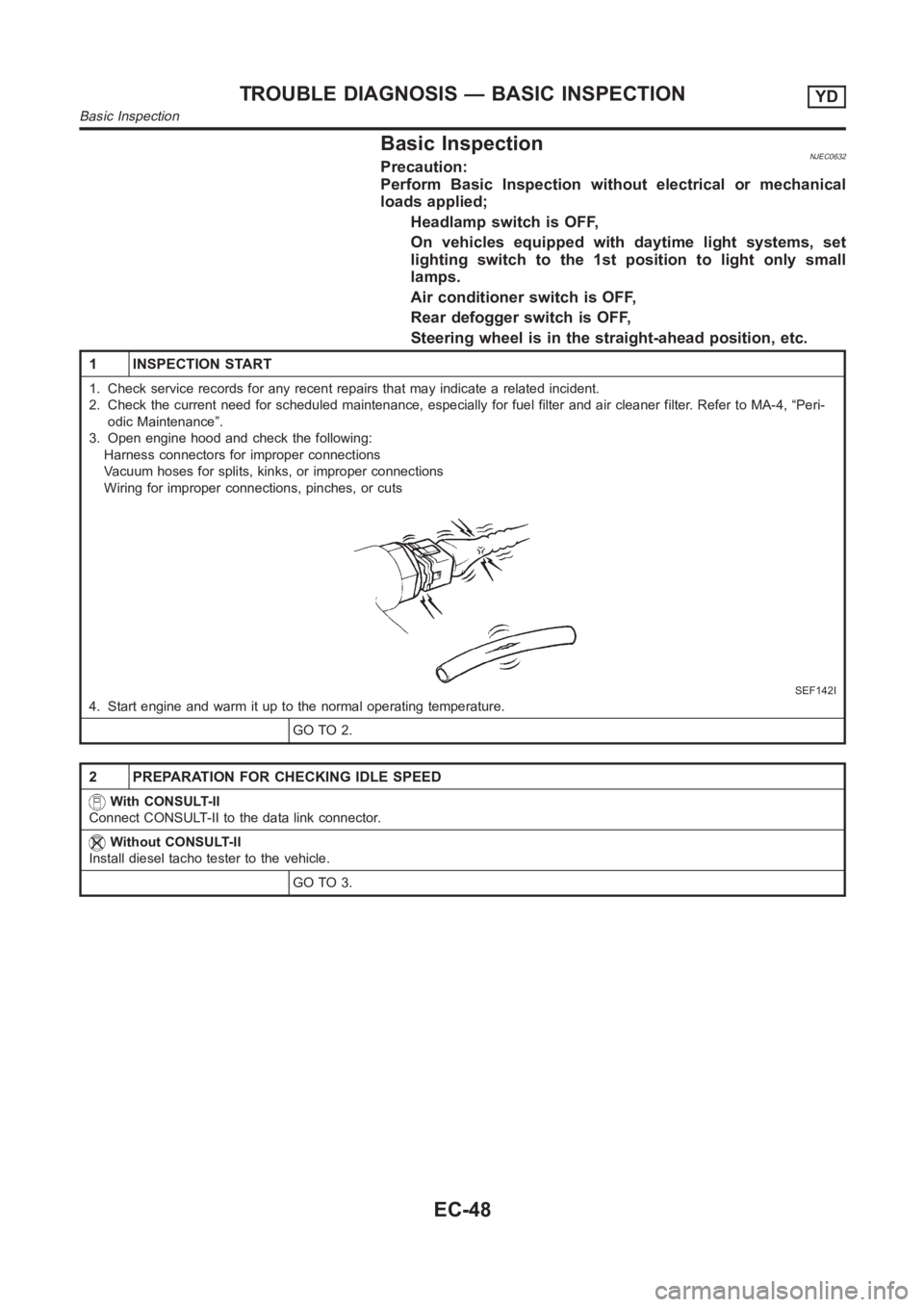
Basic InspectionNJEC0632Precaution:
Perform Basic Inspection without electrical or mechanical
loads applied;
Headlamp switch is OFF,
On vehicles equipped with daytime light systems, set
lighting switch to the 1st position to light only small
lamps.
Air conditioner switch is OFF,
Rear defogger switch is OFF,
Steering wheel is in the straight-ahead position, etc.
1 INSPECTION START
1. Check service records for any recent repairs that may indicate a relatedincident.
2. Check the current need for scheduled maintenance, especially for fuel filter and air cleaner filter. Refer to MA-4, “Peri-
odic Maintenance”.
3. Open engine hood and check the following:
Harness connectors for improper connections
Vacuum hoses for splits, kinks, or improper connections
Wiring for improper connections, pinches, or cuts
SEF142I
4. Start engine and warm it up to the normal operating temperature.
GO TO 2.
2 PREPARATION FOR CHECKING IDLE SPEED
With CONSULT-II
Connect CONSULT-II to the data link connector.
Without CONSULT-II
Install diesel tacho tester to the vehicle.
GO TO 3.
TROUBLE DIAGNOSIS — BASIC INSPECTIONYD
Basic Inspection
EC-48
Page 2070 of 3189
ATC-90
TROUBLE DIAGNOSIS
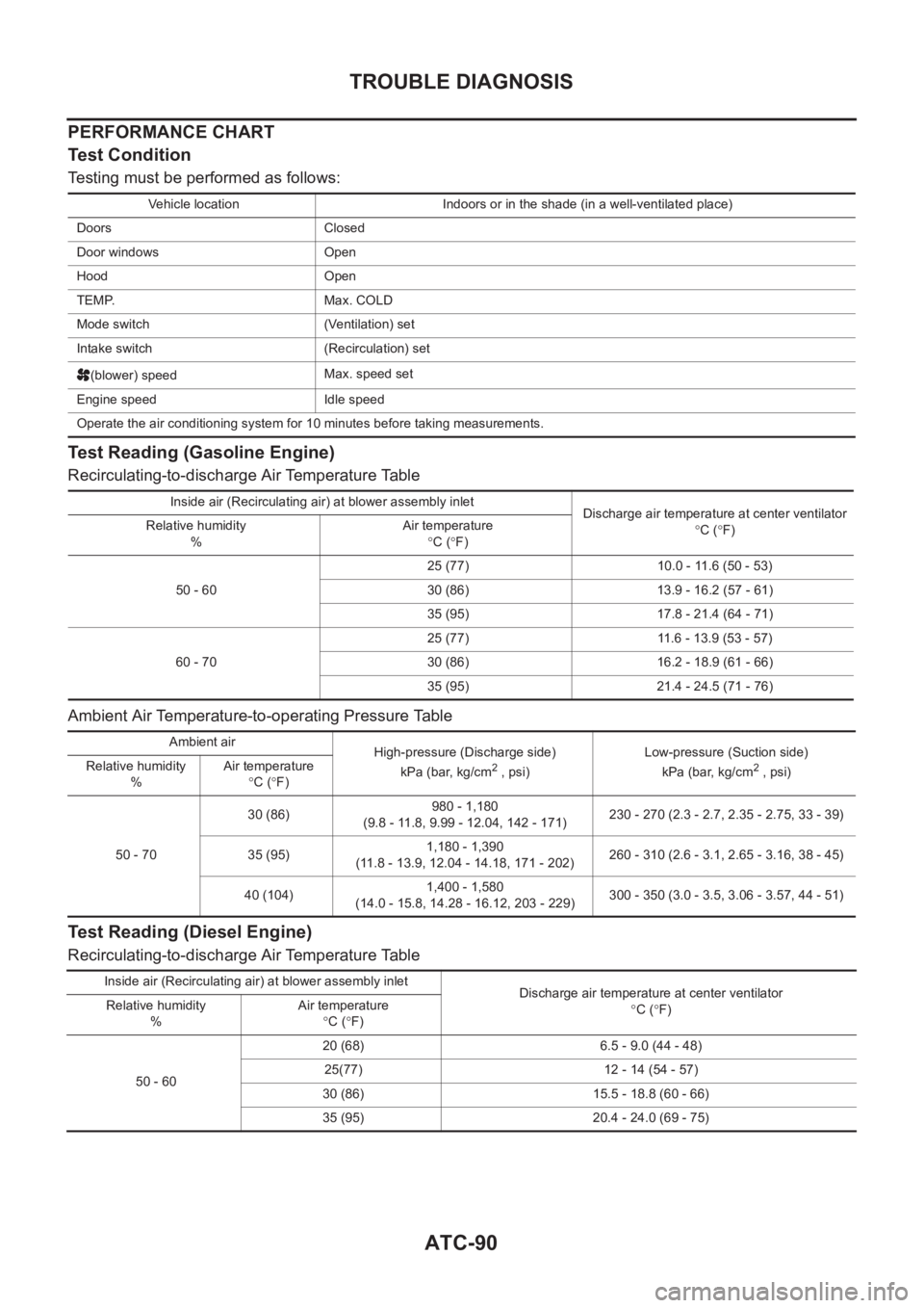
PERFORMANCE CHART
Test Condition
Testing must be performed as follows:
Test Reading (Gasoline Engine)
Recirculating-to-discharge Air Temperature Table
Ambient Air Temperature-to-operating Pressure Table
Test Reading (Diesel Engine)
Recirculating-to-discharge Air Temperature Table
Vehicle location Indoors or in the shade (in a well-ventilated place)
Doors Closed
Door windows Open
Hood Open
TEMP. Max. COLD
Mode switch (Ventilation) set
Intake switch (Recirculation) set
(blower) speedMax. speed set
Engine speed Idle speed
Operate the air conditioning system for 10 minutes before taking measurements.
Inside air (Recirculating air) at blower assembly inlet
Discharge air temperature at center ventilator
°C (°F) Relative humidity
%Air temperature
°C (°F)
50 - 6025 (77) 10.0 - 11.6 (50 - 53)
30 (86) 13.9 - 16.2 (57 - 61)
35 (95) 17.8 - 21.4 (64 - 71)
60 - 7025 (77) 11.6 - 13.9 (53 - 57)
30 (86) 16.2 - 18.9 (61 - 66)
35 (95) 21.4 - 24.5 (71 - 76)
Ambient air
High-pressure (Discharge side)
kPa (bar, kg/cm
2 , psi)Low-pressure (Suction side)
kPa (bar, kg/cm2 , psi) Relative humidity
%Air temperature
°C (°F)
50 - 7030 (86)980 - 1,180
(9.8 - 11.8, 9.99 - 12.04, 142 - 171)230 - 270 (2.3 - 2.7, 2.35 - 2.75, 33 - 39)
35 (95)1,180 - 1,390
(11.8 - 13.9, 12.04 - 14.18, 171 - 202)260 - 310 (2.6 - 3.1, 2.65 - 3.16, 38 - 45)
40 (104)1,400 - 1,580
(14.0 - 15.8, 14.28 - 16.12, 203 - 229)300 - 350 (3.0 - 3.5, 3.06 - 3.57, 44 - 51)
Inside air (Recirculating air) at blower assembly inlet
Discharge air temperature at center ventilator
°C (°F) Relative humidity
%Air temperature
°C (°F)
50 - 6020 (68) 6.5 - 9.0 (44 - 48)
25(77) 12 - 14 (54 - 57)
30 (86) 15.5 - 18.8 (60 - 66)
35 (95) 20.4 - 24.0 (69 - 75)
Page 2264 of 3189
Checking Body CorrosionNJBT0033Visually check the body sheet metal panel for corrosion, paint damage (scratches, chipping, rubbing, etc.) or
damage to the anti-corrosion materials. In particular, check the following locations.
Hemmed portion
Hood front end, door lower end, trunk lid rear end, etc.
Panel joint
Side sill of rear fender and center pillar, rear wheel housing of rear fender, around strut tower in engine
compartment, etc.
Panel edge
Trunk lid opening, sunroof opening, fender wheelarch flange, fuel fillerlid flange, around holes in panel, etc.
Parts contact
Waist molding, windshield molding, bumper, etc.
Protectors
Damage or condition of mudguard, fender protector, chipping protector, etc.
Anti-corrosion materials
Damage or separation of anti-corrosion materials under the body.
Drain holes
Condition of drain holes at door and side sill.
When repairing corroded areas, refer to the Corrosion Repair Manual.
CHASSIS AND BODY MAINTENANCE
Checking Body Corrosion
BT-6
Page 2265 of 3189
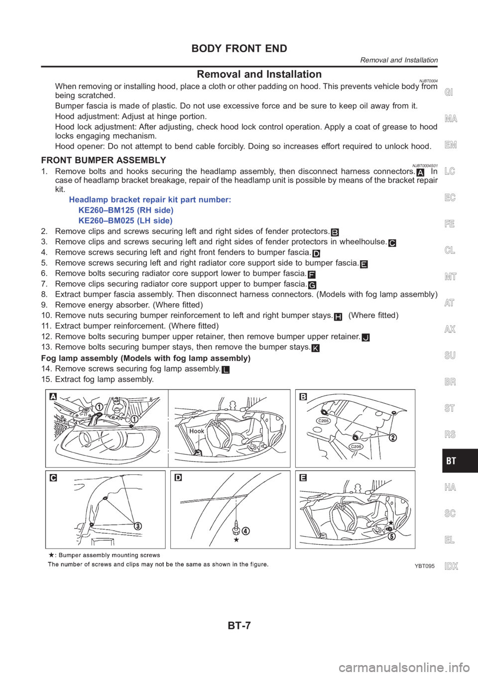
Removal and InstallationNJBT0004When removing or installing hood, place a cloth or other padding on hood. This prevents vehicle body from
being scratched.
Bumper fascia is made of plastic. Do not use excessive force and be sure to keep oil away from it.
Hood adjustment: Adjust at hinge portion.
Hood lock adjustment: After adjusting, check hood lock control operation. Apply a coat of grease to hood
locks engaging mechanism.
Hood opener: Do not attempt to bend cable forcibly. Doing so increases effort required to unlock hood.
FRONT BUMPER ASSEMBLYNJBT0004S011. Remove bolts and hooks securing the headlamp assembly, then disconnectharness connectors.In
case of headlamp bracket breakage, repair of the headlamp unit is possibleby means of the bracket repair
kit.
Headlamp bracket repair kit part number:
KE260–BM125 (RH side)
KE260–BM025 (LH side)
2. Remove clips and screws securing left and right sides of fender protectors.
3. Remove clips and screws securing left and right sides of fender protectors in wheelhoulse.
4. Remove screws securing left and right front fenders to bumper fascia.
5. Remove screws securing left and right radiator core support side to bumper fascia.
6. Remove bolts securing radiator core support lower to bumper fascia.
7. Remove clips securing radiator core support upper to bumper fascia.
8. Extract bumper fascia assembly. Then disconnect harness connectors. (Models with fog lamp assembly)
9. Remove energy absorber. (Where fitted)
10. Remove nuts securing bumper reinforcement to left and right bumper stays.
(Where fitted)
11. Extract bumper reinforcement. (Where fitted)
12. Remove bolts securing bumper upper retainer, then remove bumper upperretainer.
13. Remove bolts securing bumper stays, then remove the bumper stays.
Fog lamp assembly (Models with fog lamp assembly)
14. Remove screws securing fog lamp assembly.
15. Extract fog lamp assembly.
YBT095
GI
MA
EM
LC
EC
FE
CL
MT
AT
AX
SU
BR
ST
RS
HA
SC
EL
IDX
BODY FRONT END
Removal and Installation
BT-7
Page 2704 of 3189
DescriptionNJEL0583The Smart Entrance Control Unit is applied for QG engine models and YD engine models with common rail.
OUTLINENJEL0583S01The smart entrance control unit totally controls the following body electrical system operations.
Warning chime, refer to EL-136, “WARNING CHIME”.
Rear defogger and door mirror defogger, refer to EL-173, “REAR WINDOW DEFOGGER”.
Power door lock, refer to EL-261, “POWER DOOR LOCK SYSTEM”.
Power door lock - Super lock - (RHD models), refer to EL-301, “POWER DOOR LOCK — SUPER LOCK
—”.
Multi-remote control system, refer to EL-352, “MULTI-REMOTE CONTROL SYSTEM”.
NATS (Nissan Anti-Theft system), refer to EL-386, “NATS (NISSAN ANTI-THEFT SYSTEM)”.
Interior lamp, refer to EL-80, “INTERIOR ROOM LAMP”.
Also, smart entrance control unit has the “sleep/wake-up control” function. Smart entrance control unit puts
itself (the whole smart entrance control unit) to sleep under certain conditions to prevent unnecessary power
consumption. Then, when a certain input is detected, the system wakes itself up. For more detailed
information, refer to EL-368, “SLEEP/WAKE-UP CONTROL”.
INTERIOR LAMP/SPOT LAMP/VANITY MIRROR ILLUMINATIONNJEL0583S02The lamps turn off automatically when the interior lamp, spot lamp or/and vanity mirror illumination are illumi-
nated with the ignition key in the OFF position, if the lamp remains lit by the door switch open signal or if the
lamp switch is in the ON position for more than 30 minutes.
After lamps are turned off by the smart entrance control unit, the lamps illuminate again when:
Driver’s door is locked or unlocked with remote controller, door lock/unlock switch or door key cylinder.
Ignition switch is turned to ON.
Door is opened or closed,
Key is inserted into ignition key cylinder.
REAR WINDOW DEFOGGER/DOOR MIRROR DEFOGGERNJEL0583S03Rear window defogger is turned off in approximately 15 minutes after the rear window defogger switch is turned
on.
SLEEP/WAKE-UP CONTROLNJEL0583S04Sleep ControlNJEL0583S0401“Sleep” control prevents unnecessary power consumption. After the following conditions are met, the smart
entrance control unit suspends the operation. The whole smart entrance control unit is set in the “sleep” mode.
Ignition switch “OFF”
All electrical loads (in the smart entrance control unit) “OFF”
Timer “OFF”
Each switch do not input
Wake-up ControlNJEL0583S0402When the smart entrance control unit detects a “wake-up” signal, it wakes up the whole system and starts
operating again. When any one of the following switches are turned ON, the “sleep” mode is canceled:
Ignition switch
Hazard switch
Headlamp switch
Hood switch
Trunk room lamp switch (sedan models)
Back door switch (hatchback or wagon models)
Each door switch
Trunk release switch (sedan models)
Back door release switch (hatchback or wagon models)
External trunk release switch (sedan models)
External back door release switch (hatchback or wagon models)
SMART ENTRANCE CONTROL SYSTEM
Description
EL-368