rims NISSAN ALMERA N16 2003 Electronic Repair Manual
[x] Cancel search | Manufacturer: NISSAN, Model Year: 2003, Model line: ALMERA N16, Model: NISSAN ALMERA N16 2003Pages: 3189, PDF Size: 54.76 MB
Page 58 of 3189

NJMA0036
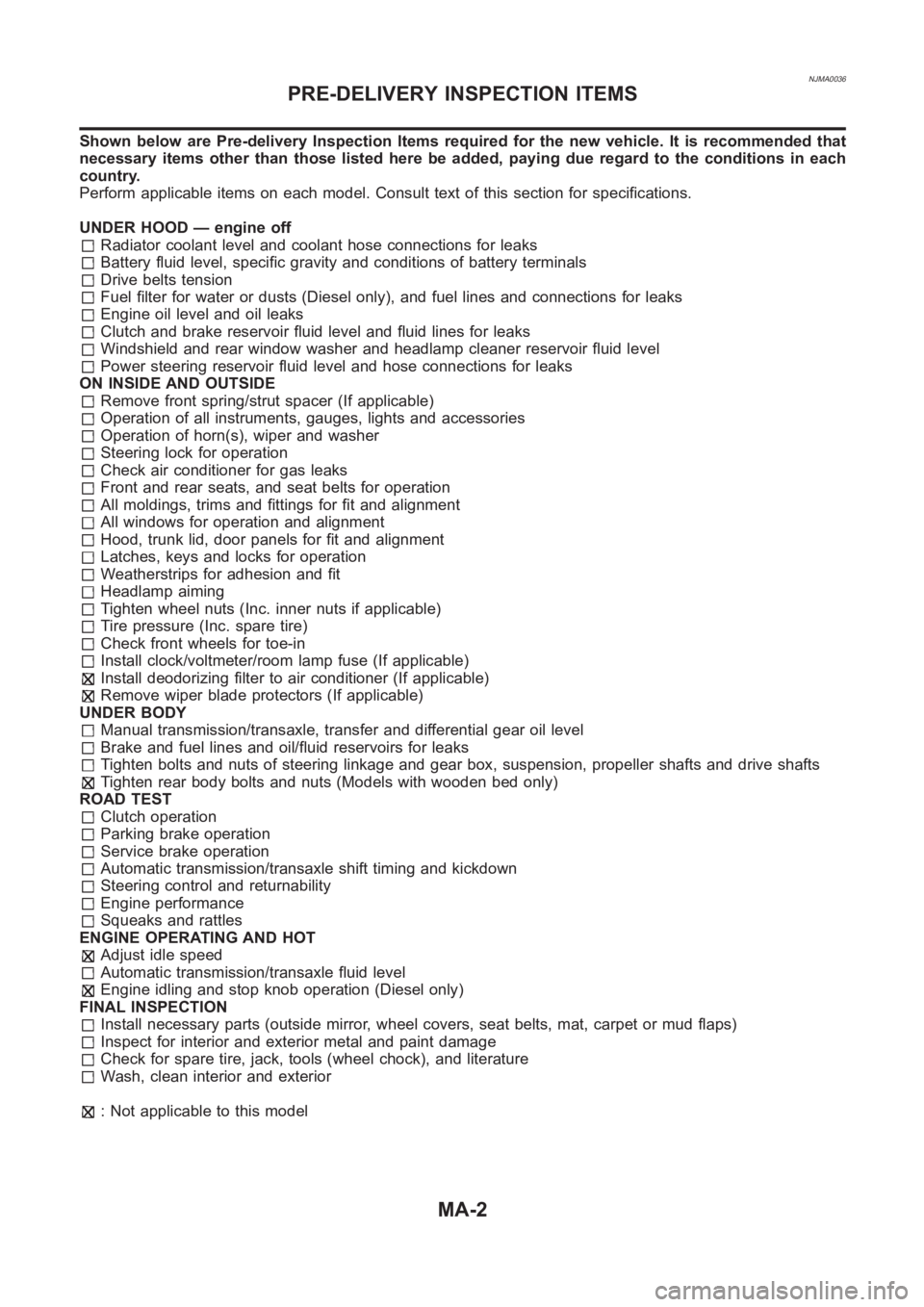
Shown below are Pre-delivery Inspection Items required for the new vehicle. It is recommended that
necessary items other than those listed here be added, paying due regard tothe conditions in each
country.
Perform applicable items on each model. Consult text of this section for specifications.
UNDER HOOD — engine off
Radiator coolant level and coolant hose connections for leaks
Battery fluid level, specific gravity and conditions of battery terminals
Drive belts tension
Fuel filter for water or dusts (Diesel only), and fuel lines and connections for leaks
Engine oil level and oil leaks
Clutch and brake reservoir fluid level and fluid lines for leaks
Windshield and rear window washer and headlamp cleaner reservoir fluid level
Power steering reservoir fluid level and hose connections for leaks
ON INSIDE AND OUTSIDE
Remove front spring/strut spacer (If applicable)
Operation of all instruments, gauges, lights and accessories
Operation of horn(s), wiper and washer
Steering lock for operation
Check air conditioner for gas leaks
Front and rear seats, and seat belts for operation
All moldings, trims and fittings for fit and alignment
All windows for operation and alignment
Hood, trunk lid, door panels for fit and alignment
Latches, keys and locks for operation
Weatherstrips for adhesion and fit
Headlamp aiming
Tighten wheel nuts (Inc. inner nuts if applicable)
Tire pressure (Inc. spare tire)
Check front wheels for toe-in
Install clock/voltmeter/room lamp fuse (If applicable)
Install deodorizing filter to air conditioner (If applicable)
Remove wiper blade protectors (If applicable)
UNDER BODY
Manual transmission/transaxle, transfer and differential gear oil level
Brake and fuel lines and oil/fluid reservoirs for leaks
Tighten bolts and nuts of steering linkage and gear box, suspension, propeller shafts and drive shafts
Tighten rear body bolts and nuts (Models with wooden bed only)
ROAD TEST
Clutch operation
Parking brake operation
Service brake operation
Automatic transmission/transaxle shift timing and kickdown
Steering control and returnability
Engine performance
Squeaks and rattles
ENGINE OPERATING AND HOT
Adjust idle speed
Automatic transmission/transaxle fluid level
Engine idling and stop knob operation (Diesel only)
FINAL INSPECTION
Install necessary parts (outside mirror, wheel covers, seat belts, mat, carpet or mud flaps)
Inspect for interior and exterior metal and paint damage
Check for spare tire, jack, tools (wheel chock), and literature
Wash, clean interior and exterior
: Not applicable to this model
PRE-DELIVERY INSPECTION ITEMS
MA-2
Page 201 of 3189

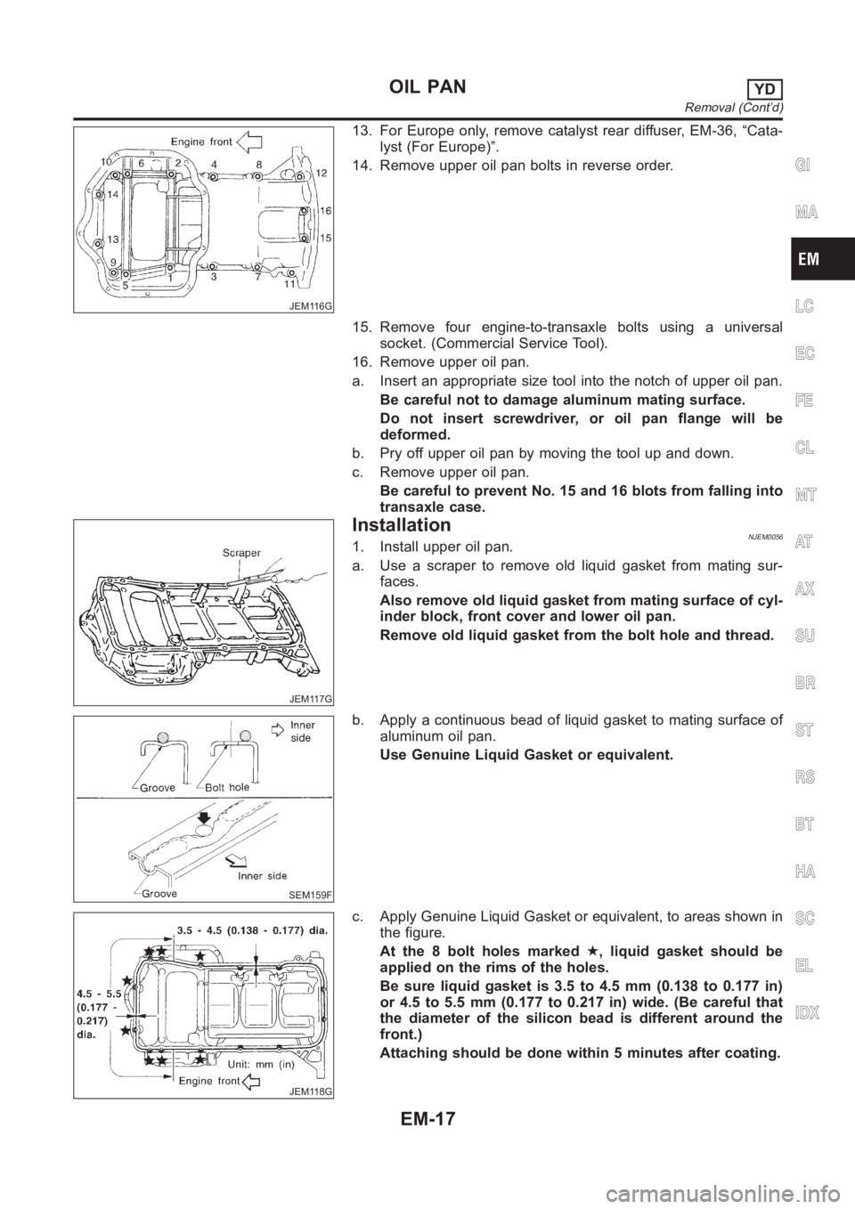
JEM116G
13. For Europe only, remove catalyst rear diffuser, EM-36, “Cata-
lyst (For Europe)”.
14. Remove upper oil pan bolts in reverse order.
15. Remove four engine-to-transaxle bolts using a universal
socket. (Commercial Service Tool).
16. Remove upper oil pan.
a. Insert an appropriate size tool into the notch of upper oil pan.
Be careful not to damage aluminum mating surface.
Do not insert screwdriver, or oil pan flange will be
deformed.
b. Pry off upper oil pan by moving the tool up and down.
c. Remove upper oil pan.
Be careful to prevent No. 15 and 16 blots from falling into
transaxle case.
JEM117G
InstallationNJEM00561. Install upper oil pan.
a. Use a scraper to remove old liquid gasket from mating sur-
faces.
Also remove old liquid gasket from mating surface of cyl-
inder block, front cover and lower oil pan.
Remove old liquid gasket from the bolt hole and thread.
SEM159F
b. Apply a continuous bead of liquid gasket to mating surface of
aluminum oil pan.
Use Genuine Liquid Gasket or equivalent.
JEM118G
c. Apply Genuine Liquid Gasket or equivalent, to areas shown in
the figure.
At the 8 bolt holes marked★, liquid gasket should be
applied on the rims of the holes.
Be sure liquid gasket is 3.5 to 4.5 mm (0.138 to 0.177 in)
or 4.5 to 5.5 mm (0.177 to 0.217 in) wide. (Be careful that
the diameter of the silicon bead is different around the
front.)
Attaching should be done within 5 minutes after coating.
GI
MA
LC
EC
FE
CL
MT
AT
AX
SU
BR
ST
RS
BT
HA
SC
EL
IDX
OIL PANYD
Removal (Cont’d)
EM-17