transmission fluid NISSAN ALMERA N16 2003 Electronic Repair Manual
[x] Cancel search | Manufacturer: NISSAN, Model Year: 2003, Model line: ALMERA N16, Model: NISSAN ALMERA N16 2003Pages: 3189, PDF Size: 54.76 MB
Page 13 of 3189
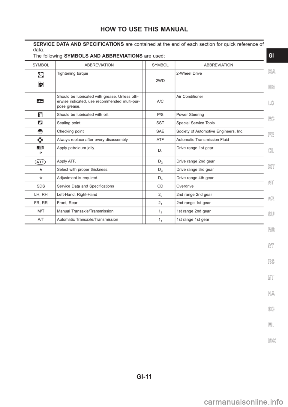
SERVICE DATA AND SPECIFICATIONSare contained at the end of each section for quick reference of
data.
The followingSYMBOLS AND ABBREVIATIONSare used:
SYMBOL ABBREVIATION SYMBOL ABBREVIATION
Tightening torque
2WD2-Wheel Drive
Should be lubricated with grease. Unless oth-
erwise indicated, use recommended multi-pur-
pose grease.A/CAir Conditioner
Should be lubricated with oil. P/S Power Steering
Sealing point SST Special Service Tools
Checking point SAE Society of Automotive Engineers, Inc.
Always replace after every disassembly. ATF Automatic Transmission Fluid
P
Apply petroleum jelly.
D1Drive range 1st gear
Apply ATF. D2Drive range 2nd gear
★Select with proper thickness. D
3Drive range 3rd gear
✩Adjustment is required. D
4Drive range 4th gear
SDS Service Data and Specifications OD Overdrive
LH, RH Left-Hand, Right-Hand 2
22nd range 2nd gear
FR, RR Front, Rear 2
12nd range 1st gear
M/T Manual Transaxle/Transmission 1
21st range 2nd gear
A/T Automatic Transaxle/Transmission 1
11st range 1st gear
MA
EM
LC
EC
FE
CL
MT
AT
AX
SU
BR
ST
RS
BT
HA
SC
EL
IDX
HOW TO USE THIS MANUAL
GI-11
Page 58 of 3189
NJMA0036
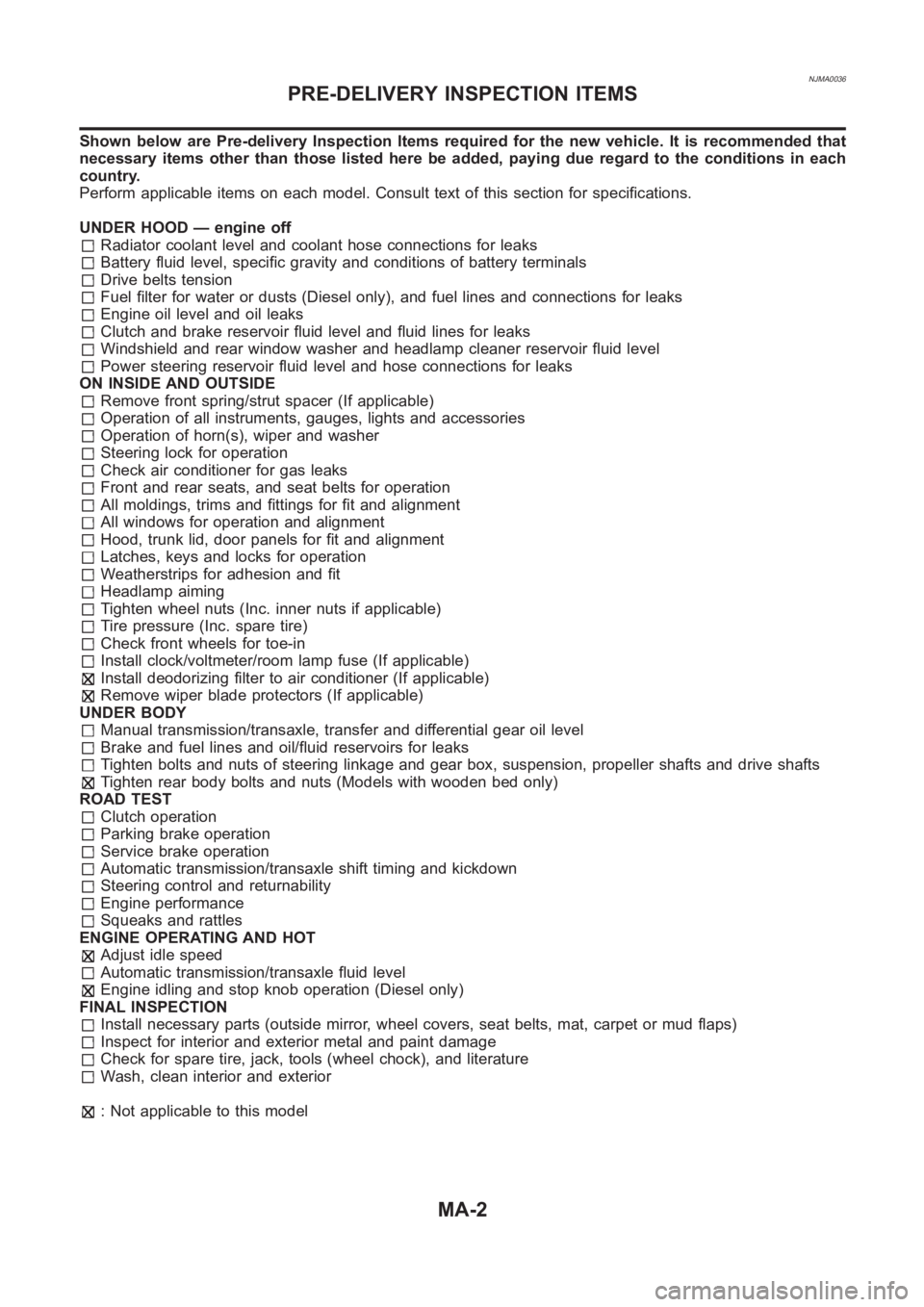
Shown below are Pre-delivery Inspection Items required for the new vehicle. It is recommended that
necessary items other than those listed here be added, paying due regard tothe conditions in each
country.
Perform applicable items on each model. Consult text of this section for specifications.
UNDER HOOD — engine off
Radiator coolant level and coolant hose connections for leaks
Battery fluid level, specific gravity and conditions of battery terminals
Drive belts tension
Fuel filter for water or dusts (Diesel only), and fuel lines and connections for leaks
Engine oil level and oil leaks
Clutch and brake reservoir fluid level and fluid lines for leaks
Windshield and rear window washer and headlamp cleaner reservoir fluid level
Power steering reservoir fluid level and hose connections for leaks
ON INSIDE AND OUTSIDE
Remove front spring/strut spacer (If applicable)
Operation of all instruments, gauges, lights and accessories
Operation of horn(s), wiper and washer
Steering lock for operation
Check air conditioner for gas leaks
Front and rear seats, and seat belts for operation
All moldings, trims and fittings for fit and alignment
All windows for operation and alignment
Hood, trunk lid, door panels for fit and alignment
Latches, keys and locks for operation
Weatherstrips for adhesion and fit
Headlamp aiming
Tighten wheel nuts (Inc. inner nuts if applicable)
Tire pressure (Inc. spare tire)
Check front wheels for toe-in
Install clock/voltmeter/room lamp fuse (If applicable)
Install deodorizing filter to air conditioner (If applicable)
Remove wiper blade protectors (If applicable)
UNDER BODY
Manual transmission/transaxle, transfer and differential gear oil level
Brake and fuel lines and oil/fluid reservoirs for leaks
Tighten bolts and nuts of steering linkage and gear box, suspension, propeller shafts and drive shafts
Tighten rear body bolts and nuts (Models with wooden bed only)
ROAD TEST
Clutch operation
Parking brake operation
Service brake operation
Automatic transmission/transaxle shift timing and kickdown
Steering control and returnability
Engine performance
Squeaks and rattles
ENGINE OPERATING AND HOT
Adjust idle speed
Automatic transmission/transaxle fluid level
Engine idling and stop knob operation (Diesel only)
FINAL INSPECTION
Install necessary parts (outside mirror, wheel covers, seat belts, mat, carpet or mud flaps)
Inspect for interior and exterior metal and paint damage
Check for spare tire, jack, tools (wheel chock), and literature
Wash, clean interior and exterior
: Not applicable to this model
PRE-DELIVERY INSPECTION ITEMS
MA-2
Page 75 of 3189
NJMA0006
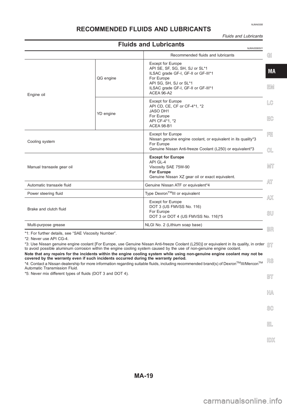
Fluids and LubricantsNJMA0006S01
Recommended fluids and lubricants
Engine oilQG engineExcept for Europe
API SE, SF, SG, SH, SJ or SL*1
ILSAC grade GF-I, GF-II or GF-III*1
For Europe
API SG, SH, SJ or SL*1
ILSAC grade GF-I, GF-II or GF-III*1
ACEA 96-A2
YD engineExcept for Europe
API CD, CE, CF or CF-4*1, *2
JASO DH1
For Europe
API CF-4*1, *2
ACEA 98-B1
Cooling systemExcept for Europe
Nissan genuine engine coolant, or equivalent in its quality*3
For Europe
Genuine Nissan Anti-freeze Coolant (L250) or equivalent*3
Manual transaxle gear oilExcept for Europe
API GL-4
Viscosity SAE 75W-90
For Europe
Genuine Nissan XZ gear oil or exact equivalent.
Automatic transaxle fluid Genuine Nissan ATF or equivalent*4
Power steering fluid Type Dexron
TMIII or equivalent
Brake and clutch fluidExcept for Europe
DOT 3 (US FMVSS No. 116)
For Europe
DOT 3 or DOT 4 (US FMVSS No. 116)*5
Multi-purpose grease NLGI No. 2 (Lithium soap base)
*1: For further details, see “SAE Viscosity Number”.
*2: Never use API CG-4.
*3: Use Nissan genuine engine coolant [For Europe, use Genuine Nissan Anti-freeze Coolant (L250)] or equivalent in its quality, in order
to avoid possible aluminum corrosion within the engine cooling system caused by the use of non-genuine engine coolant.
Note that any repairs for the incidents within the engine cooling system while using non-genuine engine coolant may not be
covered by the warranty even if such incidents occurred during the warranty period.
*4: Contact a Nissan dealership for more information regarding suitable fluids, including recommended brand(s) of Dexron
TMIII/MerconTM
Automatic Transmission Fluid.
*5: Never mix different types of fluids (DOT 3 and DOT 4).
GI
EM
LC
EC
FE
CL
MT
AT
AX
SU
BR
ST
RS
BT
HA
SC
EL
IDX
RECOMMENDED FLUIDS AND LUBRICANTS
Fluids and Lubricants
MA-19
Page 248 of 3189
crankshaft position sensor (TDC sensor) from the assem-
bly.
Always pay extra attention not to damage edge of crank-
shaft position sensor (TDC sensor) or ring gear teeth.
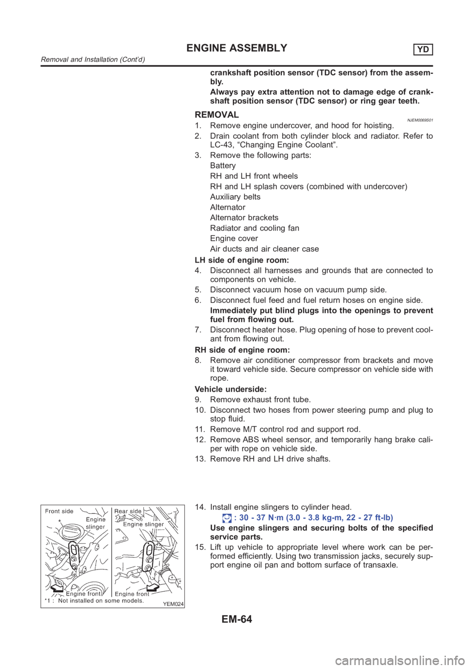
REMOVALNJEM0069S011. Remove engine undercover, and hood for hoisting.
2. Drain coolant from both cylinder block and radiator. Refer to
LC-43, “Changing Engine Coolant”.
3. Remove the following parts:
Battery
RH and LH front wheels
RH and LH splash covers (combined with undercover)
Auxiliary belts
Alternator
Alternator brackets
Radiator and cooling fan
Engine cover
Air ducts and air cleaner case
LH side of engine room:
4. Disconnect all harnesses and grounds that are connected to
components on vehicle.
5. Disconnect vacuum hose on vacuum pump side.
6. Disconnect fuel feed and fuel return hoses on engine side.
Immediately put blind plugs into the openings to prevent
fuel from flowing out.
7. Disconnect heater hose. Plug opening of hose to prevent cool-
ant from flowing out.
RH side of engine room:
8. Remove air conditioner compressor from brackets and move
it toward vehicle side. Secure compressor on vehicle side with
rope.
Vehicle underside:
9. Remove exhaust front tube.
10. Disconnect two hoses from power steering pump and plug to
stop fluid.
11. Remove M/T control rod and support rod.
12. Remove ABS wheel sensor, and temporarily hang brake cali-
per with rope on vehicle side.
13. Remove RH and LH drive shafts.
YEM024
14. Install engine slingers to cylinder head.
: 30 - 37 N·m (3.0 - 3.8 kg-m, 22 - 27 ft-lb)
Use engine slingers and securing bolts of the specified
service parts.
15. Lift up vehicle to appropriate level where work can be per-
formed efficiently. Using two transmission jacks, securely sup-
port engine oil pan and bottom surface of transaxle.
ENGINE ASSEMBLYYD
Removal and Installation (Cont’d)
EM-64
Page 362 of 3189
![NISSAN ALMERA N16 2003 Electronic Repair Manual EC-32
[QG (WITH EURO-OBD)]
BASIC SERVICE PROCEDURE
PREPARATION
Before performing “Idle Air Volume Learning”, make sure that all of the following conditions are satisfied.
Learning will be cancelle NISSAN ALMERA N16 2003 Electronic Repair Manual EC-32
[QG (WITH EURO-OBD)]
BASIC SERVICE PROCEDURE
PREPARATION
Before performing “Idle Air Volume Learning”, make sure that all of the following conditions are satisfied.
Learning will be cancelle](/img/5/57350/w960_57350-361.png)
EC-32
[QG (WITH EURO-OBD)]
BASIC SERVICE PROCEDURE
PREPARATION
Before performing “Idle Air Volume Learning”, make sure that all of the following conditions are satisfied.
Learning will be cancelled if any of the following conditions are missed for even a moment.
●Battery voltage: More than 12.9V (At idle)
●Engine coolant temperature: 70 - 95°C (158 - 203°F)
●PNP switch: ON
●Electric load switch: OFF
(Air conditioner, headlamp, rear window defogger)
On vehicles equipped with daytime light systems, set lighting switch to the 1st position to light
only small lamps.
●Steering wheel: Neutral (Straight-ahead position)
●Vehicle speed: Stopped
●Transmission: Warmed-up
For A/T models with CONSULT-II, drive vehicle until “FLUID TEMP SE” in “DATA MONITOR” mode of “A/
T” system indicates less than 0.9V.
For A/T models without CONSULT-II and M/T models, drive vehicle for 10 minutes.
OPERATION PROCEDURE
With CONSULT-II
1. Perform EC-31, "Accelerator Pedal Released Position Learning" .
2. Perform EC-31, "
Throttle Valve Closed Position Learning" .
3. Start engine and warm it up to normal operating temperature.
4. Check that all items listed under the topic “PREPARATION” (previously mentioned) are in good order.
5. Select “IDLE AIR VOL LEARN” in “WORK SUPPORT” mode.
6. Touch “START” and wait 20 seconds.
SEF217Z
SEF454Y
Page 435 of 3189
![NISSAN ALMERA N16 2003 Electronic Repair Manual TROUBLE DIAGNOSIS - SPECIFICATION VALUE
EC-105
[QG (WITH EURO-OBD)]
C
D
E
F
G
H
I
J
K
L
MA
EC
TROUBLE DIAGNOSIS - SPECIFICATION VALUEPFP:00031
DescriptionEBS00K3Y
The specification (SP) value indicate NISSAN ALMERA N16 2003 Electronic Repair Manual TROUBLE DIAGNOSIS - SPECIFICATION VALUE
EC-105
[QG (WITH EURO-OBD)]
C
D
E
F
G
H
I
J
K
L
MA
EC
TROUBLE DIAGNOSIS - SPECIFICATION VALUEPFP:00031
DescriptionEBS00K3Y
The specification (SP) value indicate](/img/5/57350/w960_57350-434.png)
TROUBLE DIAGNOSIS - SPECIFICATION VALUE
EC-105
[QG (WITH EURO-OBD)]
C
D
E
F
G
H
I
J
K
L
MA
EC
TROUBLE DIAGNOSIS - SPECIFICATION VALUEPFP:00031
DescriptionEBS00K3Y
The specification (SP) value indicates the tolerance of the value that is displayed in “DATA MONITOR (SPEC)”
mode of CONSULT-II during normal operation of the Engine Control System. When the value in “DATA MONI-
TOR (SPEC)” mode is within the SP value, the Engine Control System is confirmed OK. When the value in
“DATA MONITOR (SPEC)” mode is NOT within the SP value, the Engine Control System may have one or
more malfunctions.
The SP value is used to detect malfunctions that may affect the Engine Control System, but will not light the
MIL.
The SP value will be displayed for the following three items:
●B/FUEL SCHDL (The fuel injection pulse width programmed into ECM prior to any learned on board cor-
rection)
●A/F ALPHA-B1 (The mean value of air-fuel ratio feedback correction factor per cycle)
●MAS A/F SE-B1 (The signal voltage of the mass air flow sensor)
Testing ConditionEBS00K3Z
●Vehicle driven distance: More than 5,000 km (3,017 miles)
●Barometric pressure: 98.3 - 104.3 kPa (0.983 - 1.043 bar, 1.003 - 1.064 kg/cm2 , 14.25 - 15.12 psi)
●Atmospheric temperature: 20 - 30°C (68 - 86°F)
●Engine coolant temperature: 75 - 95°C (167 - 203°F)
●Transmission: Warmed-up*1
●Electrical load: Not applied*2
●Engine speed: Idle
*1: For A/T models, after the engine is warmed up to normal operating temperature, drive vehicle until “FLUID
TEMP SE” (A/T fluid temperature sensor signal) indicates more than 60°C (140°F).
For M/T models, after the engine is warmed up to normal operating temperature, drive vehicle for 5 minutes.
*2: Rear window defogger switch, air conditioner switch, lighting switch are “OFF”. Steering wheel is straight
ahead.
Inspection ProcedureEBS00K40
NOTE:
Perform “DATA MONITOR (SPEC)” mode in maximum scale display.
1. Perform EC-65, "
Basic Inspection" .
2. Confirm that the testing conditions indicated above are met.
3. Select “B/FUEL SCHDL”, “A/F ALPHA-B1/B2” and “MAS A/F
SE-B1” in “DATA MONITOR (SPEC)” mode with CONSULT-II.
4. Make sure that monitor items are within the SP value.
5. If NG, go to EC-106, "
Diagnostic Procedure" .
SEF601Z
Page 756 of 3189
![NISSAN ALMERA N16 2003 Electronic Repair Manual EC-426
[QG (WITHOUT EURO-OBD)]
BASIC SERVICE PROCEDURE
●Transmission: Warmed-up
For A/T models with CONSULT-II, drive vehicle until “FLUID TEMP SE” in “DATA MONITOR” mode of “A/
T” syste NISSAN ALMERA N16 2003 Electronic Repair Manual EC-426
[QG (WITHOUT EURO-OBD)]
BASIC SERVICE PROCEDURE
●Transmission: Warmed-up
For A/T models with CONSULT-II, drive vehicle until “FLUID TEMP SE” in “DATA MONITOR” mode of “A/
T” syste](/img/5/57350/w960_57350-755.png)
EC-426
[QG (WITHOUT EURO-OBD)]
BASIC SERVICE PROCEDURE
●Transmission: Warmed-up
For A/T models with CONSULT-II, drive vehicle until “FLUID TEMP SE” in “DATA MONITOR” mode of “A/
T” system indicates less than 0.9V.
For A/T models without CONSULT-II and M/T models, drive vehicle for 10 minutes.
OPERATION PROCEDURE
With CONSULT-II
1. Perform EC-425, "Accelerator Pedal Released Position Learning" .
2. Perform EC-425, "
Throttle Valve Closed Position Learning" .
3. Start engine and warm it up to normal operating temperature.
4. Check that all items listed under the topic “PREPARATION” (previously mentioned) are in good order.
5. Select “IDLE AIR VOL LEARN” in “WORK SUPPORT” mode.
6. Touch “START” and wait 20 seconds.
7. Make sure that “CMPLT” is displayed on CONSULT-II screen. If
“CMPLT” is not displayed, “Idle Air Volume Learning” will not be
carried out successfully. In this case, find the cause of the inci-
dent by referring to the “Diagnostic Procedure” below.
8. Rev up the engine two or three times and make sure that idle
speed and ignition timing are within the specifications.
Without CONSULT-II
NOTE:
●It is better to count the time accurately with a clock.
●It is impossible to switch the diagnostic mode when an accelerator pedal position sensor circuit
has a malfunction.
1. Perform EC-425, "
Accelerator Pedal Released Position Learning" .
2. Perform EC-425, "
Throttle Valve Closed Position Learning" .
3. Start engine and warm it up to normal operating temperature.
SEF217Z
SEF454Y
ITEM SPECIFICATION
Idle speed M/T: 700±50 rpm
A/T: 800±50 rpm (in “P” or “N” position)
Ignition timing M/T: 8±5° BTDC
A/T: 10±5° BTDC (in “P” or “N” position)
MBIB0238E
Page 811 of 3189
![NISSAN ALMERA N16 2003 Electronic Repair Manual TROUBLE DIAGNOSIS - SPECIFICATION VALUE
EC-481
[QG (WITHOUT EURO-OBD)]
C
D
E
F
G
H
I
J
K
L
MA
EC
TROUBLE DIAGNOSIS - SPECIFICATION VALUEPFP:00031
DescriptionEBS00KF3
The specification (SP) value indic NISSAN ALMERA N16 2003 Electronic Repair Manual TROUBLE DIAGNOSIS - SPECIFICATION VALUE
EC-481
[QG (WITHOUT EURO-OBD)]
C
D
E
F
G
H
I
J
K
L
MA
EC
TROUBLE DIAGNOSIS - SPECIFICATION VALUEPFP:00031
DescriptionEBS00KF3
The specification (SP) value indic](/img/5/57350/w960_57350-810.png)
TROUBLE DIAGNOSIS - SPECIFICATION VALUE
EC-481
[QG (WITHOUT EURO-OBD)]
C
D
E
F
G
H
I
J
K
L
MA
EC
TROUBLE DIAGNOSIS - SPECIFICATION VALUEPFP:00031
DescriptionEBS00KF3
The specification (SP) value indicates the tolerance of the value that is displayed in “DATA MONITOR (SPEC)”
mode of CONSULT-II during normal operation of the Engine Control System. When the value in “DATA MONI-
TOR (SPEC)” mode is within the SP value, the Engine Control System is confirmed OK. When the value in
“DATA MONITOR (SPEC)” mode is NOT within the SP value, the Engine Control System may have one or
more malfunctions.
The SP value is used to detect malfunctions that may affect the Engine Control System, but will not light the
MI.
The SP value will be displayed for the following three items:
●B/FUEL SCHDL (The fuel injection pulse width programmed into ECM prior to any learned on board cor-
rection)
●A/F ALPHA-B1 (The mean value of air-fuel ratio feedback correction factor per cycle)
●MAS A/F SE-B1 (The signal voltage of the mass air flow sensor)
Testing ConditionEBS00KF4
●Vehicle driven distance: More than 5,000 km (3,017 miles)
●Barometric pressure: 98.3 - 104.3 kPa (0.983 - 1.043 bar, 1.003 - 1.064 kg/cm2 , 14.25 - 15.12 psi)
●Atmospheric temperature: 20 - 30°C (68 - 86°F)
●Engine coolant temperature: 75 - 95°C (167 - 203°F)
●Transmission: Warmed-up*1
●Electrical load: Not applied*2
●Engine speed: Idle
*1: For A/T models, after the engine is warmed up to normal operating temperature, drive vehicle until “FLUID
TEMP SE” (A/T fluid temperature sensor signal) indicates more than 60°C (140°F).
For M/T models, after the engine is warmed up to normal operating temperature, drive vehicle for 5 minutes.
*2: Rear window defogger switch, air conditioner switch, lighting switch are “OFF”. Steering wheel is straight
ahead.
Inspection ProcedureEBS00KF5
NOTE:
Perform “DATA MONITOR (SPEC)” mode in maximum scale display.
1. Perform EC-443, "
Basic Inspection" .
2. Confirm that the testing conditions indicated above are met.
3. Select “B/FUEL SCHDL”, “A/F ALPHA-B1” and “MAS A/F SE-
B1” in “DATA MONITOR (SPEC)” mode with CONSULT-II.
4. Make sure that monitor items are within the SP value.
5. If NG, go to EC-482, "
Diagnostic Procedure" .
SEF601Z
Page 1457 of 3189
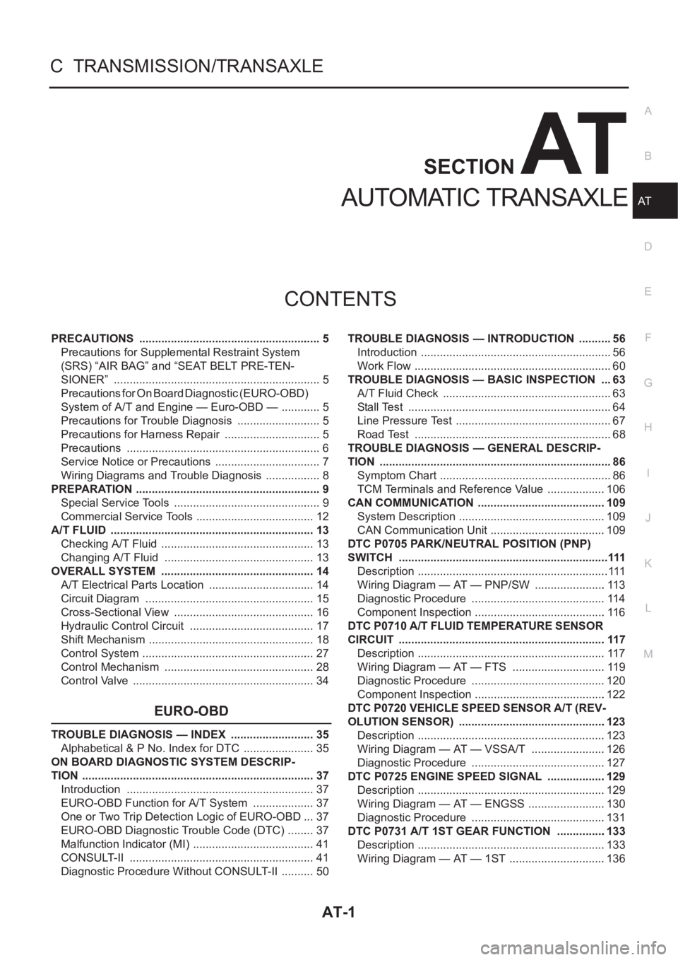
AT-1
AUTOMATIC TRANSAXLE
C TRANSMISSION/TRANSAXLE
CONTENTS
D
E
F
G
H
I
J
K
L
M
SECTION
A
B
AT
AUTOMATIC TRANSAXLE
PRECAUTIONS .......................................................... 5
Precautions for Supplemental Restraint System
(SRS) “AIR BAG” and “SEAT BELT PRE-TEN-
SIONER” .................................................................. 5
Precautions for On Board Diagnostic (EURO-OBD)
System of A/T and Engine — Euro-OBD — ............. 5
Precautions for Trouble Diagnosis ........................... 5
Precautions for Harness Repair ............................... 5
Precautions .............................................................. 6
Service Notice or Precautions .................................. 7
Wiring Diagrams and Trouble Diagnosis .................. 8
PREPARATION ........................................................... 9
Special Service Tools ............................................... 9
Commercial Service Tools ...................................... 12
A/T FLUID ................................................................. 13
Checking A/T Fluid ................................................. 13
Changing A/T Fluid ............................................. ... 13
OVERALL SYSTEM ................................................. 14
A/T Electrical Parts Location .................................. 14
Circuit Diagram ...................................................... 15
Cross-Sectional View ............................................. 16
Hydraulic Control Circuit ........................................ 17
Shift Mechanism ..................................................... 18
Control System ....................................................... 27
Control Mechanism ................................................ 28
Control Valve .......................................................... 34
EURO-OBD
TROUBLE DIAGNOSIS — INDEX ........................... 35
Alphabetical & P No. Index for DTC ....................... 35
ON BOARD DIAGNOSTIC SYSTEM DESCRIP-
TION .......................................................................... 37
Introduction ............................................................ 37
EURO-OBD Function for A/T System .................... 37
One or Two Trip Detection Logic of EURO-OBD ... 37
EURO-OBD Diagnostic Trouble Code (DTC) ......... 37
Malfunction Indicator (MI) ....................................... 41
CONSULT-II ........................................................... 41
Diagnostic Procedure Without CONSULT-II ........... 50TROUBLE DIAGNOSIS — INTRODUCTION ........... 56
Introduction ............................................................. 56
Work Flow ............................................................... 60
TROUBLE DIAGNOSIS — BASIC INSPECTION .... 63
A/T Fluid Check ...................................................... 63
Stall Test ................................................................. 64
Line Pressure Test .................................................. 67
Road Test ............................................................... 68
TROUBLE DIAGNOSIS — GENERAL DESCRIP-
TION .......................................................................... 86
Symptom Chart ....................................................... 86
TCM Terminals and Reference Value ...................106
CAN COMMUNICATION .........................................109
System Description ...............................................109
CAN Communication Unit .....................................109
DTC P0705 PARK/NEUTRAL POSITION (PNP)
SWITCH ...................................................................111
Description .............................................................111
Wiring Diagram — AT — PNP/SW .......................113
Diagnostic Procedure ...........................................114
Component Inspection ..........................................116
DTC P0710 A/T FLUID TEMPERATURE SENSOR
CIRCUIT ..................................................................117
Description ............................................................117
Wiring Diagram — AT — FTS ..............................119
Diagnostic Procedure ...........................................120
Component Inspection ..........................................122
DTC P0720 VEHICLE SPEED SENSOR A/T (REV-
OLUTION SENSOR) ...............................................123
Description ............................................................123
Wiring Diagram — AT — VSSA/T ........................126
Diagnostic Procedure ...........................................127
DTC P0725 ENGINE SPEED SIGNAL ...................129
Description ............................................................129
Wiring Diagram — AT — ENGSS .........................130
Diagnostic Procedure ..........................................
.131
DTC P0731 A/T 1ST GEAR FUNCTION ................133
Description ............................................................133
Wiring Diagram — AT — 1ST ...............................136
Page 1484 of 3189
AT-28
OVERALL SYSTEM
TCM FUNCTION
The function of the TCM is to:
●Receive input signals sent from various switches and sensors.
●Determine required line pressure, shifting point, lock-up operation, and engine brake operation.
●Send required output signals to the respective solenoid valves.
INPUT/OUTPUT SIGNAL OF TCM
Control MechanismECS007NK
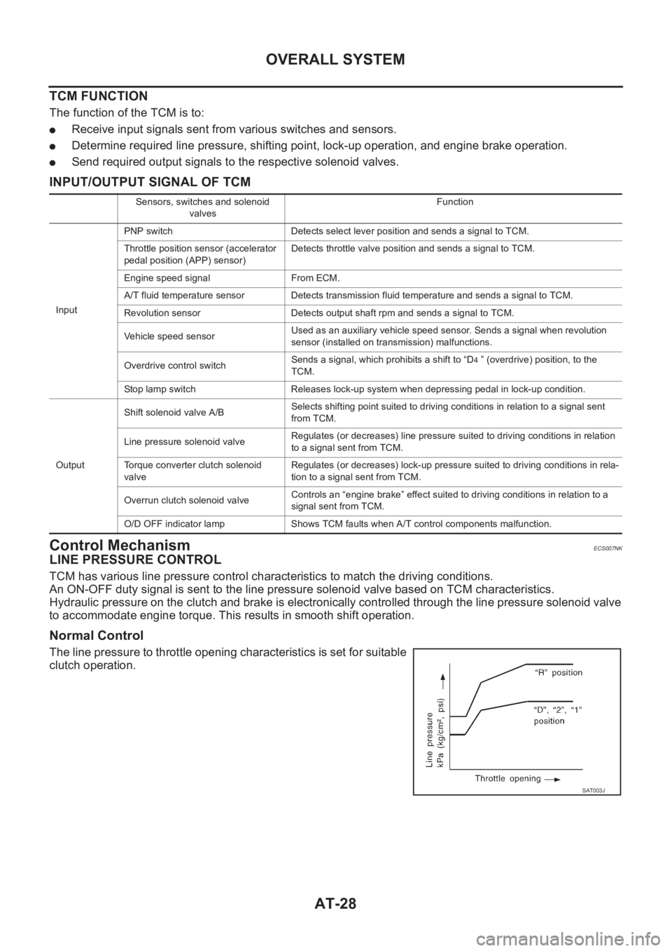
LINE PRESSURE CONTROL
TCM has various line pressure control characteristics to match the driving conditions.
An ON-OFF duty signal is sent to the line pressure solenoid valve based on TCM characteristics.
Hydraulic pressure on the clutch and brake is electronically controlled through the line pressure solenoid valve
to accommodate engine torque. This results in smooth shift operation.
Normal Control
The line pressure to throttle opening characteristics is set for suitable
clutch operation.
Sensors, switches and solenoid
valvesFunction
InputPNP switch Detects select lever position and sends a signal to TCM.
Throttle position sensor (accelerator
pedal position (APP) sensor)Detects throttle valve position and sends a signal to TCM.
Engine speed signal From ECM.
A/T fluid temperature sensor Detects transmission fluid temperature and sends a signal to TCM.
Revolution sensor Detects output shaft rpm and sends a signal to TCM.
Vehicle speed sensorUsed as an auxiliary vehicle speed sensor. Sends a signal when revolution
sensor (installed on transmission) malfunctions.
Overdrive control switchSends a signal, which prohibits a shift to “D
4 ” (overdrive) position, to the
TCM.
Stop lamp switch Releases lock-up system when depressing pedal in lock-up condition.
OutputShift solenoid valve A/BSelects shifting point suited to driving conditions in relation to a signal sent
from TCM.
Line pressure solenoid valveRegulates (or decreases) line pressure suited to driving conditions in relation
to a signal sent from TCM.
Torque converter clutch solenoid
valveRegulates (or decreases) lock-up pressure suited to driving conditions in rela-
tion to a signal sent from TCM.
Overrun clutch solenoid valveControls an “engine brake” effect suited to driving conditions in relation to a
signal sent from TCM.
O/D OFF indicator lamp Shows TCM faults when A/T control components malfunction.
SAT003J