remote control NISSAN ALMERA N16 2003 Electronic Repair Manual
[x] Cancel search | Manufacturer: NISSAN, Model Year: 2003, Model line: ALMERA N16, Model: NISSAN ALMERA N16 2003Pages: 3189, PDF Size: 54.76 MB
Page 2339 of 3189
Trouble Diagnoses/YD Engine Models with
Common Rail and K9K Engine Models...................292
POWER DOOR LOCK - SUPER LOCK -...................301
System Description ..................................................301
Schematic <0011001100110011001100110011001100110011001100110011001100110011001100110011001100110011001100110011001100110011001100110011001100110011001100110011001100110011001100110011001100110011001100110011001100
11001100110011[..........304
Wiring Diagram - S/LOCK - .....................................306
Trouble Diagnosis/QG and YD Engine Models
with Common Rail ...................................................313
Trouble Diagnoses/YD Engine Models without
Common Rail and K9K Engine Models...................339
MULTI-REMOTE CONTROL SYSTEM.......................352
System Description ..................................................352
Wiring Diagram - MULTI - .......................................353
Trouble Diagnoses/QG and YD Engine Models
with Common Rail ...................................................355
Trouble Diagnoses/YD Engine Models without
Common Rail and K9K Engine Models...................360
ID Code Entry Procedure ........................................364
Remote Controller Battery Replacement.................365
THEFT WARNING SYSTEM.......................................366
Wiring Diagram - PRWIRE -....................................366
SMART ENTRANCE CONTROL SYSTEM.................368
Description <0011001100110011001100110011001100110011001100110011001100110011001100110011001100110011001100110011001100110011001100110011001100110011001100110011001100110011001100110011001100110011001100110011001100
110011[...........368
CONSULT-II <0011001100110011001100110011001100110011001100110011001100110011001100110011001100110011001100110011001100110011001100110011001100110011001100110011001100110011001100110011001100110011001100110011001100
1100110011[........369
Schematic <0011001100110011001100110011001100110011001100110011001100110011001100110011001100110011001100110011001100110011001100110011001100110011001100110011001100110011001100110011001100110011001100110011001100
11001100110011[..........374
Smart Entrance Control Unit Inspection Table ........376
Trouble Diagnoses...................................................378
Power Supply and Ground Circuit Check ...............379
CAN Communication Line Check ............................380
TIME CONTROL UNIT................................................381
Description <0011001100110011001100110011001100110011001100110011001100110011001100110011001100110011001100110011001100110011001100110011001100110011001100110011001100110011001100110011001100110011001100110011001100
110011[...........381
Trouble Diagnoses...................................................382
Schematic <0011001100110011001100110011001100110011001100110011001100110011001100110011001100110011001100110011001100110011001100110011001100110011001100110011001100110011001100110011001100110011001100110011001100
11001100110011[..........384
NATS (NISSAN ANTI-THEFT SYSTEM).....................386
Component Parts and Harness Connetor
Location <0011001100110011001100110011001100110011001100110011001100110011001100110011001100110011001100110011001100110011001100110011001100110011001100110011001100110011001100110011001100110011001100110011001100
110011001100110011[............386
System Description ..................................................386
System Composition ................................................387
Wiring Diagram - NATS -.........................................388
CONSULT-II <0011001100110011001100110011001100110011001100110011001100110011001100110011001100110011001100110011001100110011001100110011001100110011001100110011001100110011001100110011001100110011001100110011001100
1100110011[........390
Trouble Diagnoses/QG and YD Engine Models
with Common Rail ...................................................393
How to Replace NATS Antenna Amp ...................... 411
Trouble Diagnoses/YD Engine Models without
Common Rail and K9K Engine Models...................412
How to Replace NATS IMMU ..................................429
NAVIGATION SYSTEM...............................................430
System Description ..................................................430
Precautions for AV and NAVI Control Unit
Replacement <0011001100110011001100110011001100110011001100110011001100110011001100110011001100110011001100110011001100110011001100110011001100110011001100110011001100110011001100110011001100110011001100110011001100
110011[........440
Component Parts Location ......................................441
Location of Antenna .................................................441Schematic <0011001100110011001100110011001100110011001100110011001100110011001100110011001100110011001100110011001100110011001100110011001100110011001100110011001100110011001100110011001100110011001100110011001100
11001100110011[..........442
Wiring Diagram - NAVI - ..........................................443
Wiring Diagram - COMM -.......................................448
Terminals and Reference Value for AV and NAVI
Control Unit <0011001100110011001100110011001100110011001100110011001100110011001100110011001100110011001100110011001100110011001100110011001100110011001100110011001100110011001100110011001100110011001100110011001100
110011[..........450
Terminals and Reference Value for Display Unit ....454
Terminals and Reference Value for Multifunction
Switch <0011001100110011001100110011001100110011001100110011001100110011001100110011001100110011001100110011001100110011001100110011001100110011001100110011001100110011001100110011001100110011001100110011001100
11001100110011001100110011[.............456
Self-Diagnosis Function ...........................................457
Self-Diagnosis Mode................................................458
Confirmation/Adjustment Mode ...............................461
Power Supply and Ground Circuit Check ...............467
Check Display Unit, Multifunction Switch Power,
and Ground Circuit ..................................................469
Vehicle Speed Signal Check ...................................471
Illumination Control Signal Check ...........................472
Ignition Signal Check ...............................................473
Reverse Signal Check .............................................474
RGB Screen Is Not Shown......................................475
No Screens Appear .................................................477
Color of RGB Image Is Not Proper .........................477
RGB Screen Is Rolling ............................................482
Guide Sound Is Not Heard ......................................484
Multifunction Switch Controls Are Ineffective
(Rear Defogger Control Excluded) ..........................485
Air Conditioning Controls (Only) Are Ineffective
(Rear Defogger Control Excluded) ..........................489
Rear Defogger Does Not Operate...........................491
Rear Defogger Indicator Lamp Does Not
Illuminate<0011001100110011001100110011001100110011001100110011001100110011001100110011001100110011001100110011001100110011001100110011001100110011001100110011001100110011001100110011001100110011001100110011001100
1100110011[.............492
No Fuel Information Is Displayed/No Warning
Message Is Displayed .............................................493
Previous Conditions Are Not Stored........................495
The Position of The Current-Location Mark Is
Not Correct <0011001100110011001100110011001100110011001100110011001100110011001100110011001100110011001100110011001100110011001100110011001100110011001100110011001100110011001100110011001100110011001100110011001100
1100110011[.........495
Radio Wave From The GPS Satellite Is Not
Received <0011001100110011001100110011001100110011001100110011001100110011001100110011001100110011001100110011001100110011001100110011001100110011001100110011001100110011001100110011001100110011001100110011001100
110011001100110011[...........495
Display Does Not Change When Screen
Adjustment Is Performed .........................................496
Day/Night Display Switching Is Not Done. Night
Illumination for AV and NAVI Control Unit Does
Not Illuminate ...........................................................496
On Multifunction Switch, a Specific Switch Does
Not Operate in All Conditions ..................................496
Driving Information Is Inaccurate. Maintenance
Information Is Inaccurate .........................................496
System Does Not Start ............................................497
The Current Position Mark Is in the Wrong Place ..497
The Current-Location Mark Will Not Move
Forward/Backward ...................................................498
The Position of the Current-Location Mark Is Not
Correct <0011001100110011001100110011001100110011001100110011001100110011001100110011001100110011001100110011001100110011001100110011001100110011001100110011001100110011001100110011001100110011001100110011001100
1100110011001100110011[.............498
GI
MA
EM
LC
EC
FE
CL
MT
AT
AX
SU
BR
ST
RS
BT
HA
SC
IDX
CONTENTS(Cont’d)
EL-3
Page 2404 of 3189
hatchback models).
With power and ground supplied, the smart entrance control unit controls the flashing of the RH turn signal
lamps, and smart entrance control unit sent RH turn signal to combination meter with CAN communication
line.
to combination meter terminal 26 and 27
from smart entrance control unit terminal 8 and 11.
HAZARD LAMP OPERATIONNJEL0430S02Power is supplied at all times
through 15A fuse [No. 5, located in fuse block (J/B)]
to smart entrance control unit terminal 56
With the hazard switch in the ON position, ground is supplied from body grounds F118 (QG engine models),
M28 and M67 to
smart entrance control unit terminal 30
through hazard switch terminals 1 and 3
With ground is supplied, smart entrance control unit controls the flashing of the hazard warning lamps.
Power is supplied from smart entrance control unit terminal 64
to front turn signal lamp LH terminal 1,
to side turn signal lamp LH terminal 2,
to rear combination lamp LH terminal 2 (for sedan models) or
to rear combination lamp LH terminal 5 (for hatchback models).
Power is supplied from smart entrance control unit terminal 63
to front turn signal lamp RH terminal 1,
to side turn signal lamp RH terminal 2,
to rear combination lamp RH terminal 2 (for sedan models) or
to rear combination lamp RH terminal 5 (for hatchback models).
Ground is supplied to terminal 2 each front turn signal lamp through body grounds E30 and E73.
Ground is supplied to terminal 1 each side turn signal lamp through body grounds E30 and E73.
Ground is supplied to terminal 1 of rear combination lamp through body grounds B9 and B21 and B308 (for
sedan models).
Ground is supplied to terminal 4 of rear combination lamp through body grounds B9, B21 and D96 (for hatch-
back models).
With power and ground supplied, the smart entrance control unit controls the flashing of the hazard warning
lamps, and smart entrance control unit sent flashing indicator signal (hazard warning signal) to combination
meter with CAN communication line.
to combination meter terminal 26 and 27
from smart entrance control unit terminals 8 and 11.
HAZARD REMINDER OPERATION FOR MULTI-REMOTE CONTROL SYSTEMNJEL0430S04When the doors are locked or unlocked by multi-remote controller, smart entrance control unit controls turn
lamps hazard reminder flashes as follows.
Locked operation: Flash once
Unlock operation: Flash twice
TURN SIGNAL AND HAZARD WARNING LAMPS
System Description/QG Engine Models and YD Engine Models with Common Rail(Cont’d)
EL-68
Page 2405 of 3189
![NISSAN ALMERA N16 2003 Electronic Repair Manual System Description/YD Engine Models with
Common Rail and K9K Engine Models
=NJEL0547TURN SIGNAL OPERATIONNJEL0547S01Power is supplied at all times
through 15A fuse [No. 5, located in fuse block (J/B)] NISSAN ALMERA N16 2003 Electronic Repair Manual System Description/YD Engine Models with
Common Rail and K9K Engine Models
=NJEL0547TURN SIGNAL OPERATIONNJEL0547S01Power is supplied at all times
through 15A fuse [No. 5, located in fuse block (J/B)]](/img/5/57350/w960_57350-2404.png)
System Description/YD Engine Models with
Common Rail and K9K Engine Models
=NJEL0547TURN SIGNAL OPERATIONNJEL0547S01Power is supplied at all times
through 15A fuse [No. 5, located in fuse block (J/B)]
to time control unit terminal 9
With the ignition switch in the ON or START position, power is supplied
through 10A fuse [No. 10, located in fuse block (J/B)]
to time control unit terminal 1
Ground is supplied to time control unit terminal 16 through body grounds M28 and M67.
LH TurnNJEL0547S0101When the turn signal switch is moved to the L position, ground is supplied from body grounds E30 and E73
to
time control unit terminal 2
through turn signal switch terminal 3
With ground is supplied, time control unit controls the flashing of the LH turn signal lamps.
RH TurnNJEL0547S0102When the turn signal switch is moved to the R position, ground is supplied from body grounds E30 and E73
to
time control unit terminal 4
through turn signal switch terminal 2
With ground is supplied, time control unit controls the flashing of the RH turn signal lamps.
HAZARD LAMP OPERATIONNJEL0547S02Power is supplied at all times
through 15A fuse [No. 5, located in fuse block (J/B)]
to time control unit terminal 9
Ground is supplied to time control unit terminal 16 through body grounds M28 and M67.
With the hazard switch in the ON position, ground is supplied from body grounds M28 and M67 to
time control unit terminals 1 and 5
through hazard switch terminal 3
With ground is supplied, time control unit controls the flashing of the hazard warning lamps.
HAZARD REMINDER OPERATION FOR MULTI-REMOTE CONTROL SYSTEMNJEL0547S03When the doors are locked or unlocked by multi-remote controller, time control unit controls turn lamps haz-
ard reminder flashes as follows.
Locked operation: Flash once
Unlock operation: Flash twice
GI
MA
EM
LC
EC
FE
CL
MT
AT
AX
SU
BR
ST
RS
BT
HA
SC
IDX
TURN SIGNAL AND HAZARD WARNING LAMPS
System Description/YD Engine Models with Common Rail and K9K Engine Models
EL-69
Page 2417 of 3189
INTERIOR ROOM LAMP TIMER OPERATIONNJEL0435S03When interior room lamp switch is in the “DOOR” position, the smart entrance control unit keeps the interior
room lamp illuminated for about 30 seconds when:
unlock signal is supplied from driver’s door lock/unlock switch while alldoors are closed
unlock signal is supplied from remote controller while all doors are closed and key is out of the ignition
key cylinder,
key is removed from ignition key cylinder while all doors are closed
driver’s door is opened and then closed while key is out of the ignition key cylinder. (However, if the driv-
er’s door is closed with the key inserted in the ignition key cylinder afterthe driver’s door is opened with
the key removed, the timer is operated
The timer is canceled when:
driver’s door is locked,
driver’s door is opened, or
ignition switch is turned ON.
ON-OFF CONTROLNJEL0435S04When the driver side door, front passenger door, rear LH or RH door is opened, the interior room lamp turns
on while the interior room lamp switch is in the “DOOR” position.
BATTERY SAVERNJEL0435S11The interior room lamp is turned OFF automatically with the lamp switch in the “DOOR” position after about
30 minutes, if the lamp remains lit by the door switch open signal.
GI
MA
EM
LC
EC
FE
CL
MT
AT
AX
SU
BR
ST
RS
BT
HA
SC
IDX
INTERIOR ROOM LAMP
System Description/QG and YD Engine Models with Common Rail (Cont’d)
EL-81
Page 2422 of 3189
Trouble Diagnoses/QG and YD Engine Models
with Common Rail
NJEL0549TERMINAL AND REFERENCE VALVE FOR SMART
ENTRANCE CONTROL UNIT
NJEL0549S01
Terminal
No.Wire
colorConnections Operated condition Voltage (Approximate values)
5 L/W Key switch Ignition key Removed,Inserted 0V,12V
13 P Door lock/unlock switches Neutral,Locks 12V,0V
14 L Door lock/unlock switches Neutral,Unlocks 12V,0V
28 R/Y Interior room lampWhen interior lamp is operated using
remote controller (Lamp switch in
“DOOR” position)12V,0V
29 Y/G Ignition key switch Ignition key is in “ON” position 12V
39 BR/WRear door switch
(LH or RH)Rear door LH or RH: Open,Closed 0V,12V
43 R/W Front door switchFront door (Driver side):
Open,Closed12V,0V
44 R/WFront door switch
(Passenger side)Front door (Passenger side):
Open,Closed0V,12V
45 R/YRear door switch
(LH or RH)Rear door LH or RH: Open,Closed 0V,12V
53 B Ground — 0V
56 R/B Power source — 12V
CONSULT-II INSPECTION PROCEDURENJEL0549S02“ROOM LAMP”
MAIA0009E
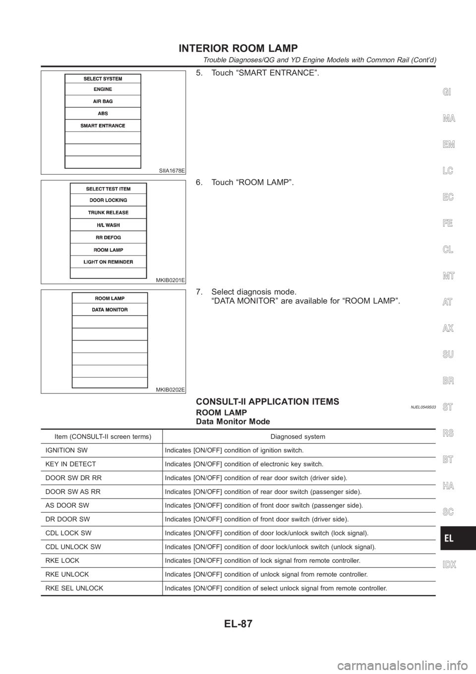
1. Turn ignition switch “OFF”.
2. Connect “CONSULT-II” to the data link connector.
MBIB0233E
3. Turn ignition switch “ON”.
4. Touch “START (NISSAN BASED VHCL)”.
INTERIOR ROOM LAMP
Trouble Diagnoses/QG and YD Engine Models with Common Rail
EL-86
Page 2423 of 3189
SIIA1678E
5. Touch “SMART ENTRANCE”.
MKIB0201E
6. Touch “ROOM LAMP”.
MKIB0202E
7. Select diagnosis mode.
“DATA MONITOR” are available for “ROOM LAMP”.
CONSULT-II APPLICATION ITEMSNJEL0549S03ROOM LAMP
Data Monitor Mode
Item (CONSULT-II screen terms) Diagnosed system
IGNITION SW Indicates [ON/OFF] condition of ignition switch.
KEY IN DETECT Indicates [ON/OFF] condition of electronic key switch.
DOOR SW DR RR Indicates [ON/OFF] condition of rear door switch (driver side).
DOOR SW AS RR Indicates [ON/OFF] condition of rear door switch (passenger side).
AS DOOR SW Indicates [ON/OFF] condition of front door switch (passenger side).
DR DOOR SW Indicates [ON/OFF] condition of front door switch (driver side).
CDL LOCK SW Indicates [ON/OFF] condition of door lock/unlock switch (locksignal).
CDL UNLOCK SW Indicates [ON/OFF] condition of door lock/unlock switch (unlock signal).
RKE LOCK Indicates [ON/OFF] condition of lock signal from remote controller.
RKE UNLOCK Indicates [ON/OFF] condition of unlock signal from remote controller.
RKE SEL UNLOCK Indicates [ON/OFF] condition of select unlock signal from remote controller.
GI
MA
EM
LC
EC
FE
CL
MT
AT
AX
SU
BR
ST
RS
BT
HA
SC
IDX
INTERIOR ROOM LAMP
Trouble Diagnoses/QG and YD Engine Models with Common Rail (Cont’d)
EL-87
Page 2478 of 3189
![NISSAN ALMERA N16 2003 Electronic Repair Manual 4. Select the desired part to be diagnosed on the “SELECT TES-
T ITEM” screen.
Data monitor item (KEY REMINDER)
Monitored item Description
IGNITION SW Indicates [ON/OFF] condition of ignition swit NISSAN ALMERA N16 2003 Electronic Repair Manual 4. Select the desired part to be diagnosed on the “SELECT TES-
T ITEM” screen.
Data monitor item (KEY REMINDER)
Monitored item Description
IGNITION SW Indicates [ON/OFF] condition of ignition swit](/img/5/57350/w960_57350-2477.png)
4. Select the desired part to be diagnosed on the “SELECT TES-
T ITEM” screen.
Data monitor item (KEY REMINDER)
Monitored item Description
IGNITION SW Indicates [ON/OFF] condition of ignition switch.
KEY IN DETECT Indicates [ON/OFF] condition of electronic key switch.
DR DOOR SW Indicates [ON/OFF] condition of front door switch (driver side).
CDL LOCK SW Indicates [ON/OFF] condition of door lock/unlock switch.
RKE LOCK Indicates [ON/OFF] condition of lock signal from remote controller.
Data monitor item (Light warning chime)
Monitored item Description
IGN ON SW Indicates [ON/OFF] condition of ignition switch.
DR DOOR SW Indicates [ON/OFF] condition of front door switch (driver side).
TAIL LAMP ON Indicates [ON/OFF] condition of lighting switch.
SYMPTOM CHARTNJEL0551S02First perform the “SELF-DIAG RESULTS” in “SMART ENTRANCE”
with CONSULT-II, when perform the each trouble diagnosis.
Symptom Diagnoses/Service procedure Reference page
Light warning chime does not activate.Power supply and ground circuit checkEL-143, “Power Supply
and Ground Circuit
Check”
Lighting switch checkEL-144, “Lighting Switch
Input Signal Check”
Front door switch (driver side) checkEL-150, “Front Door
Switch (Driver side)
Check”
Key warning chime does not activate.Power supply and ground circuit checkEL-143, “Power Supply
and Ground Circuit
Check”
Key switch insert signal checkEL-147, “Key Switch
Insert Signal Check”
Front door switch (driver side) checkEL-150, “Front Door
Switch (Driver side)
Check”
All warning chimes do not activate. Power supply and ground circuit checkEL-143, “Power Supply
and Ground Circuit
Check”
With the ignition switch turned OFF and the
door closed (driver side) turning the lighting
switch ON (1st) activates the chime.Front door switch (driver side) checkEL-150, “Front Door
Switch (Driver side)
Check”
WARNING CHIME
Trouble Diagnoses/QG and YD Engine Models with Common Rail (Cont’d)
EL-142
Page 2597 of 3189
System Description=NJEL0502OPERATIONNJEL0502S02Power door lock/unlock operation by door key cylinder
With the key inserted into front door key cylinder, turning it to LOCK will lock all doors.
With the key inserted into front door key cylinder, turning it to UNLOCK will unlock all doors.
Power door lock/unlock operation by multi-remote controller (If equipped)
Pressing multi-remote controller LOCK button will lock all doors.
Pressing multi-remote controller UNLOCK button once will unlock driver door. Then, if an unlock signal is
sent from the remote controller again within 5 seconds, all other doors will be unlocked.
Power door lock/unlock operation by lock/unlock switch
With lock/unlock switch on driver door trim setting to LOCK will lock all doors.
With lock/unlock switch on driver door trim setting to UNLOCK will unlock all doors.GI
MA
EM
LC
EC
FE
CL
MT
AT
AX
SU
BR
ST
RS
BT
HA
SC
IDX
POWER DOOR LOCK
System Description
EL-261
Page 2608 of 3189
![NISSAN ALMERA N16 2003 Electronic Repair Manual CONSULT-II APPLICATION ITEMSNJEL0580S02Door LockingNJEL0580S0201DATA MONITOR
Monitored Item Description
IGNITION SW Indicates [ON/OFF] condition of ignition switch.
KEY IN DETECT Indicates [ON/OFF] co NISSAN ALMERA N16 2003 Electronic Repair Manual CONSULT-II APPLICATION ITEMSNJEL0580S02Door LockingNJEL0580S0201DATA MONITOR
Monitored Item Description
IGNITION SW Indicates [ON/OFF] condition of ignition switch.
KEY IN DETECT Indicates [ON/OFF] co](/img/5/57350/w960_57350-2607.png)
CONSULT-II APPLICATION ITEMSNJEL0580S02Door LockingNJEL0580S0201DATA MONITOR
Monitored Item Description
IGNITION SW Indicates [ON/OFF] condition of ignition switch.
KEY IN DETECT Indicates [ON/OFF] condition of key switch.
DOOR SW DR RR Indicates [ON/OFF] condition of rear door switch (driver side).
DOOR SW AS RR Indicates [ON/OFF] condition of rear door switch (passenger side).
AS DOOR SW Indicates [ON/OFF] condition of front door switch (passenger side).
DR DOOR SW Indicates [ON\OFF] condition of front door switch (driver side).
CDL LOCK SW Indicates [ON/OFF] condition of lock signal from door lock/ unlock switch.
CDL UNLOCK SW Indicates [ON/OFF] condition of unlock signal from door lock/ unlock switch.
RKE LOCK Indicates [ON/OFF] condition of lock signal from remote controller.
RKE UNLOCK Indicates [ON/OFF] condition of unlock signal from remote controller.
RKE SEL UNLOCK Indicates [ON/OFF] condition of select unlock signal from remote controller.
WORK SUPPORT
Monitored Item Description
AUTO RE-LOCKAuto re-lock function can be changed in this mode. The re-lock mode will be changed when
“CHANGE MODE” on CONSULT-II screen is touched.
SELECTIVE UNLOCKSelective unlock function can be changed in this mode. The unlock mode willbe changed when
“CHANGE SET” on CONSULT-II screen is touched.
Trunk ReleaseNJEL0580S0202DATA MONITOR
Monitored Item Description
IGNITION SW Indicates [ON/OFF] condition of ignition switch.
TRUNK OPEN SW Indicates [ON/OFF] condition of trunk room lamp switch (sedan) or back door switch (wagon).
INT TRUNK RELIndicates [ON/OFF] condition of internal trunk release switch (sedan) orinternal back door
release switch (wagon).
EXT TRUNK RELIndicates [ON/OFF] condition of external trunk release switch (sedan) orexternal back door
release switch (wagon).
RKE TRUNK RELIndicates [ON/OFF] condition of trunk (sedan) or back door (back door) open signal from trunk
or back door release switch.
WORK SUPPORT
Monitored Item Description
TRUNK OPEN DELAYThis mode can be changed trunk release switch (sedan) or back door (wagon) release switch
operation time.
POWER DOOR LOCK
Trouble Diagnosis/QG and YD Engine Models with Common Rail (Cont’d)
EL-272
Page 2637 of 3189
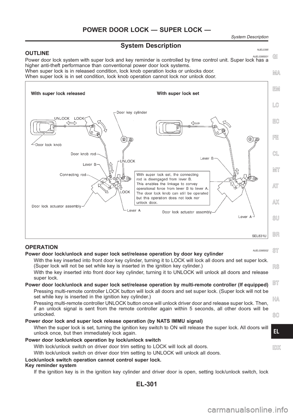
System DescriptionNJEL0395OUTLINENJEL0395S01Power door lock system with super lock and key reminder is controlled by time control unit. Super lock has a
higher anti-theft performance than conventional power door lock systems.
When super lock is in released condition, lock knob operation locks or unlocks door.
When super lock is in set condition, lock knob operation cannot lock nor unlock door.
SEL831U
OPERATIONNJEL0395S02Power door lock/unlock and super lock set/release operation by door key cylinder
With the key inserted into front door key cylinder, turning it to LOCK will lock all doors and set super lock.
(Super lock will not be set while key is inserted in the ignition key cylinder. )
With the key inserted into front door key cylinder, turning it to UNLOCK will unlock all doors and release
super lock.
Power door lock/unlock and super lock set/release operation by multi-remote controller (If equipped)
Pressing multi-remote controller LOCK button will lock all doors and set super lock. (Super lock will not be
set while key is inserted in the ignition key cylinder.)
Pressing multi-remote controller UNLOCK button once will unlock driver door and release super lock. Then,
if an unlock signal is sent from the remote controller again within 5 seconds, all other doors will be
unlocked.
Power door lock and super lock release operation (by NATS IMMU signal)
When the super lock is set, turning the ignition key switch to ON will release the super lock. All doors will
unlock once, but then immediately lock again.
Power door lock/unlock operation by lock/unlock switch
With lock/unlock switch on driver door trim setting to LOCK will lock all doors.
With lock/unlock switch on driver door trim setting to UNLOCK will unlock all doors.
Lock/unlock switch operation cannot control super lock.
Key reminder system
If the ignition key is in the ignition key cylinder and driver door is open, setting lock/unlock switch, lock
GI
MA
EM
LC
EC
FE
CL
MT
AT
AX
SU
BR
ST
RS
BT
HA
SC
IDX
POWER DOOR LOCK — SUPER LOCK —
System Description
EL-301