NISSAN ALMERA TINO 2001 Service Repair Manual
ALMERA TINO 2001
NISSAN
NISSAN
https://www.carmanualsonline.info/img/5/57352/w960_57352-0.png
NISSAN ALMERA TINO 2001 Service Repair Manual
Page 507 of 3051
SEF094Y
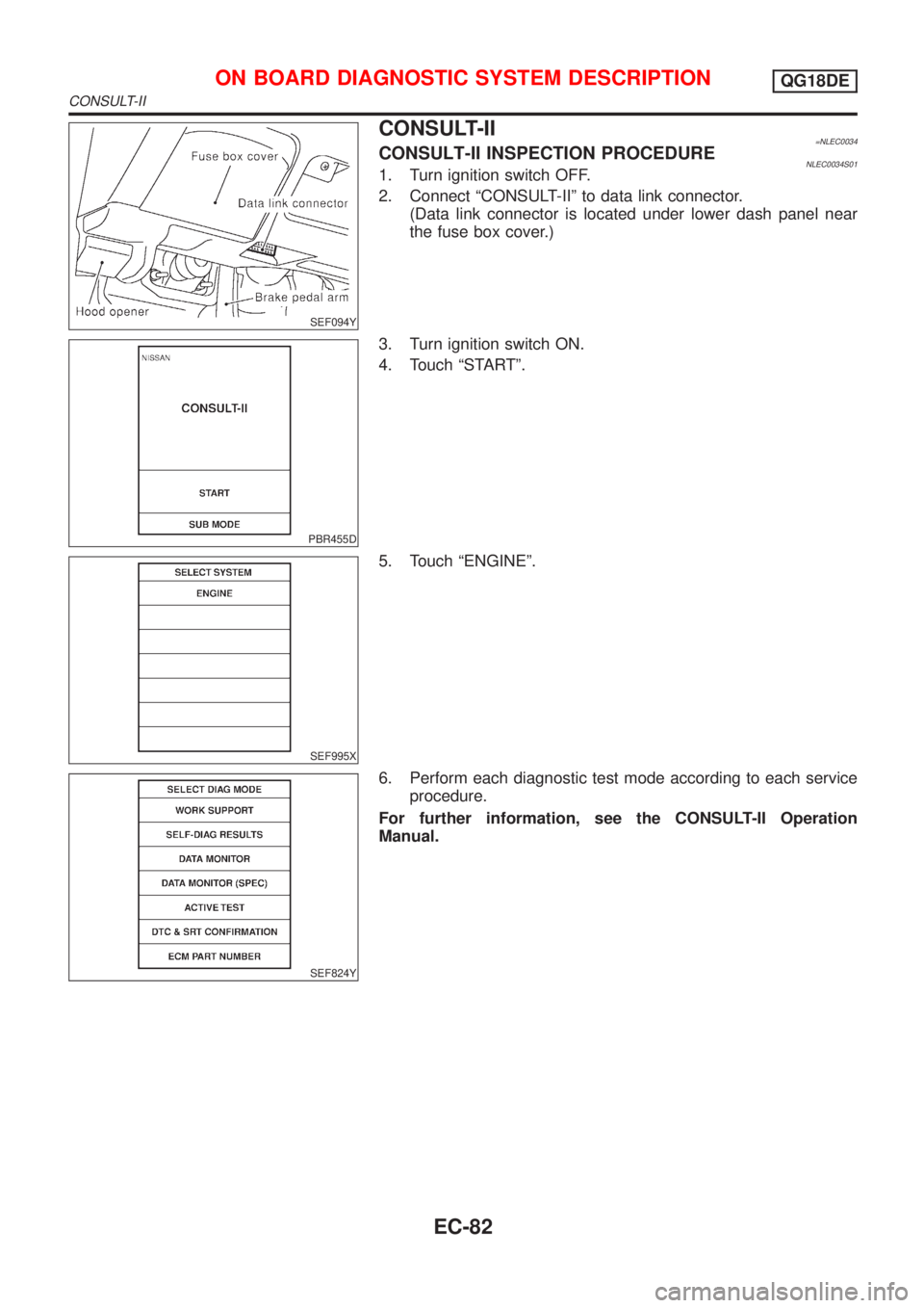
CONSULT-II=NLEC0034CONSULT-II INSPECTION PROCEDURENLEC0034S011. Turn ignition switch OFF.
2. Connect ªCONSULT-IIº to data link connector.
(Data link connector is located under lower dash panel near
the fuse box cover.)
PBR455D
3. Turn ignition switch ON.
4. Touch ªSTARTº.
SEF995X
5. Touch ªENGINEº.
SEF824Y
6. Perform each diagnostic test mode according to each service
procedure.
For further information, see the CONSULT-II Operation
Manual.
ON BOARD DIAGNOSTIC SYSTEM DESCRIPTIONQG18DE
CONSULT-II
EC-82
Page 518 of 3051
SEF139P
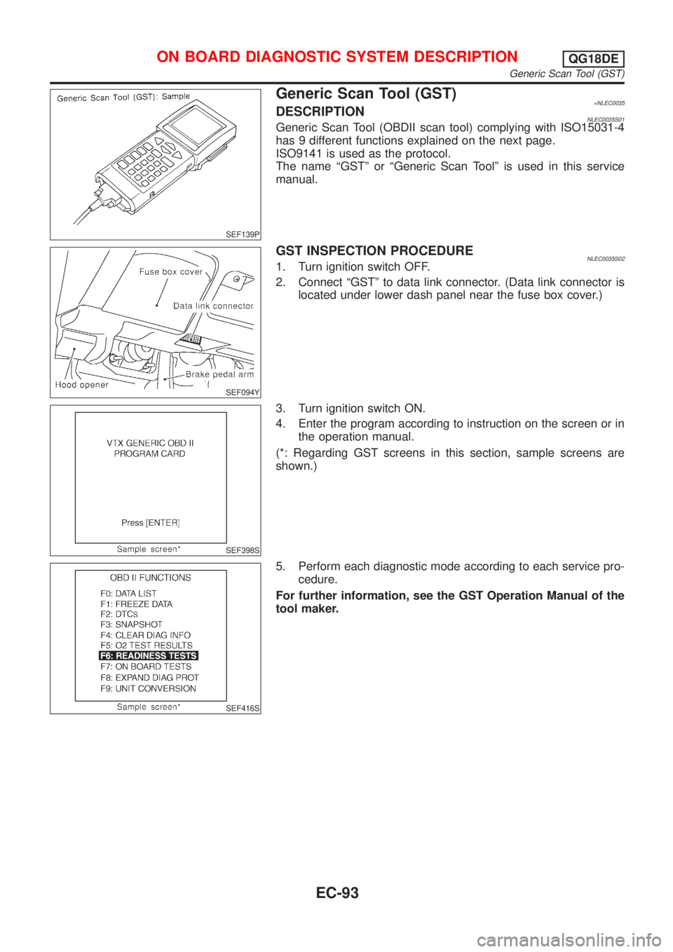
Generic Scan Tool (GST)=NLEC0035DESCRIPTIONNLEC0035S01Generic Scan Tool (OBDII scan tool) complying with ISO15031-4
has 9 different functions explained on the next page.
ISO9141 is used as the protocol.
The name ªGSTº or ªGeneric Scan Toolº is used in this service
manual.
SEF094Y
GST INSPECTION PROCEDURENLEC0035S021. Turn ignition switch OFF.
2. Connect ªGSTº to data link connector. (Data link connector is
located under lower dash panel near the fuse box cover.)
SEF398S
3. Turn ignition switch ON.
4. Enter the program according to instruction on the screen or in
the operation manual.
(*: Regarding GST screens in this section, sample screens are
shown.)
SEF416S
5. Perform each diagnostic mode according to each service pro-
cedure.
For further information, see the GST Operation Manual of the
tool maker.
ON BOARD DIAGNOSTIC SYSTEM DESCRIPTIONQG18DE
Generic Scan Tool (GST)
EC-93
Page 577 of 3051
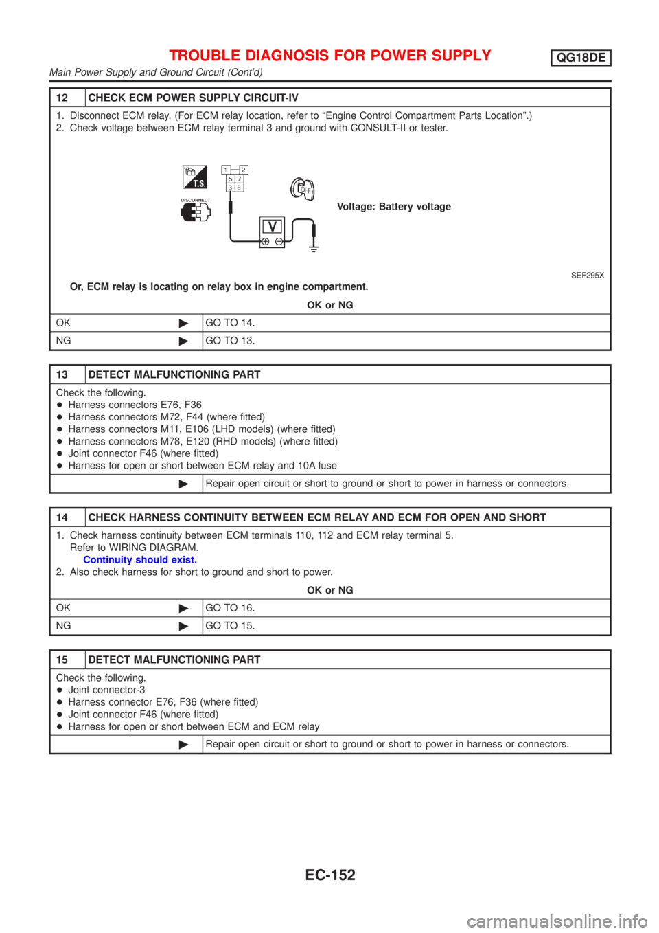
12 CHECK ECM POWER SUPPLY CIRCUIT-IV
1. Disconnect ECM relay. (For ECM relay location, refer to ªEngine Control Compartment Parts Locationº.)
2. Check voltage between ECM relay terminal 3 and ground with CONSULT-II or tester.
SEF295X
Or, ECM relay is locating on relay box in engine compartment.
OK or NG
OK©GO TO 14.
NG©GO TO 13.
13 DETECT MALFUNCTIONING PART
Check the following.
+Harness connectors E76, F36
+Harness connectors M72, F44 (where fitted)
+Harness connectors M11, E106 (LHD models) (where fitted)
+Harness connectors M78, E120 (RHD models) (where fitted)
+Joint connector F46 (where fitted)
+Harness for open or short between ECM relay and 10A fuse
©Repair open circuit or short to ground or short to power in harness or connectors.
14 CHECK HARNESS CONTINUITY BETWEEN ECM RELAY AND ECM FOR OPEN AND SHORT
1. Check harness continuity between ECM terminals 110, 112 and ECM relay terminal 5.
Refer to WIRING DIAGRAM.
Continuity should exist.
2. Also check harness for short to ground and short to power.
OK or NG
OK©GO TO 16.
NG©GO TO 15.
15 DETECT MALFUNCTIONING PART
Check the following.
+Joint connector-3
+Harness connector E76, F36 (where fitted)
+Joint connector F46 (where fitted)
+Harness for open or short between ECM and ECM relay
©Repair open circuit or short to ground or short to power in harness or connectors.
TROUBLE DIAGNOSIS FOR POWER SUPPLYQG18DE
Main Power Supply and Ground Circuit (Cont'd)
EC-152
Page 801 of 3051
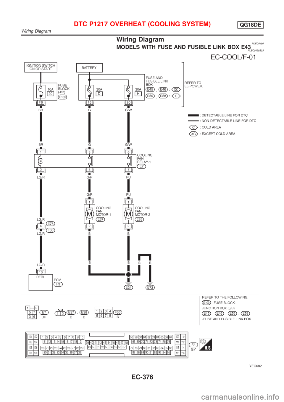
Wiring DiagramNLEC0490MODELS WITH FUSE AND FUSIBLE LINK BOX E43NLEC0490S03
YEC682
DTC P1217 OVERHEAT (COOLING SYSTEM)QG18DE
Wiring Diagram
EC-376
Page 802 of 3051
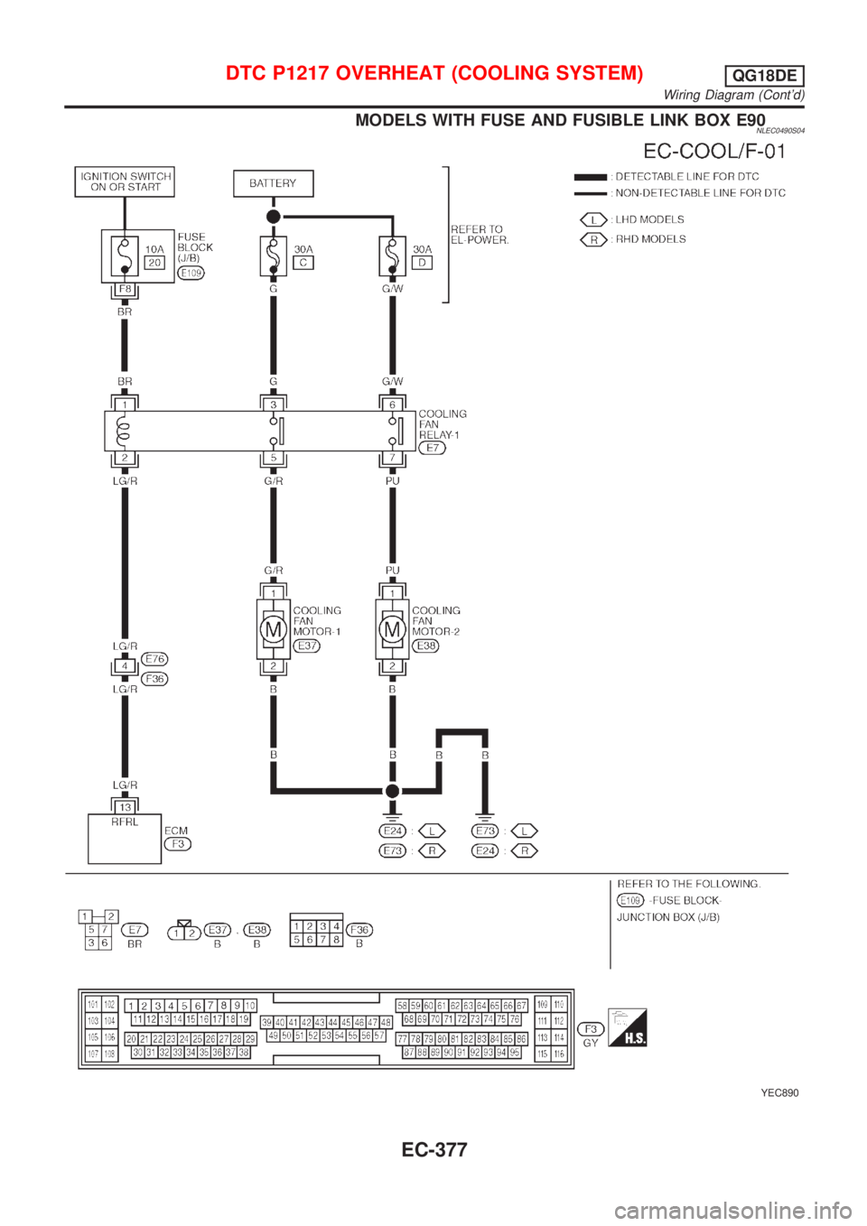
MODELS WITH FUSE AND FUSIBLE LINK BOX E90NLEC0490S04
YEC890
DTC P1217 OVERHEAT (COOLING SYSTEM)QG18DE
Wiring Diagram (Cont'd)
EC-377
Page 1032 of 3051
SEF094Y
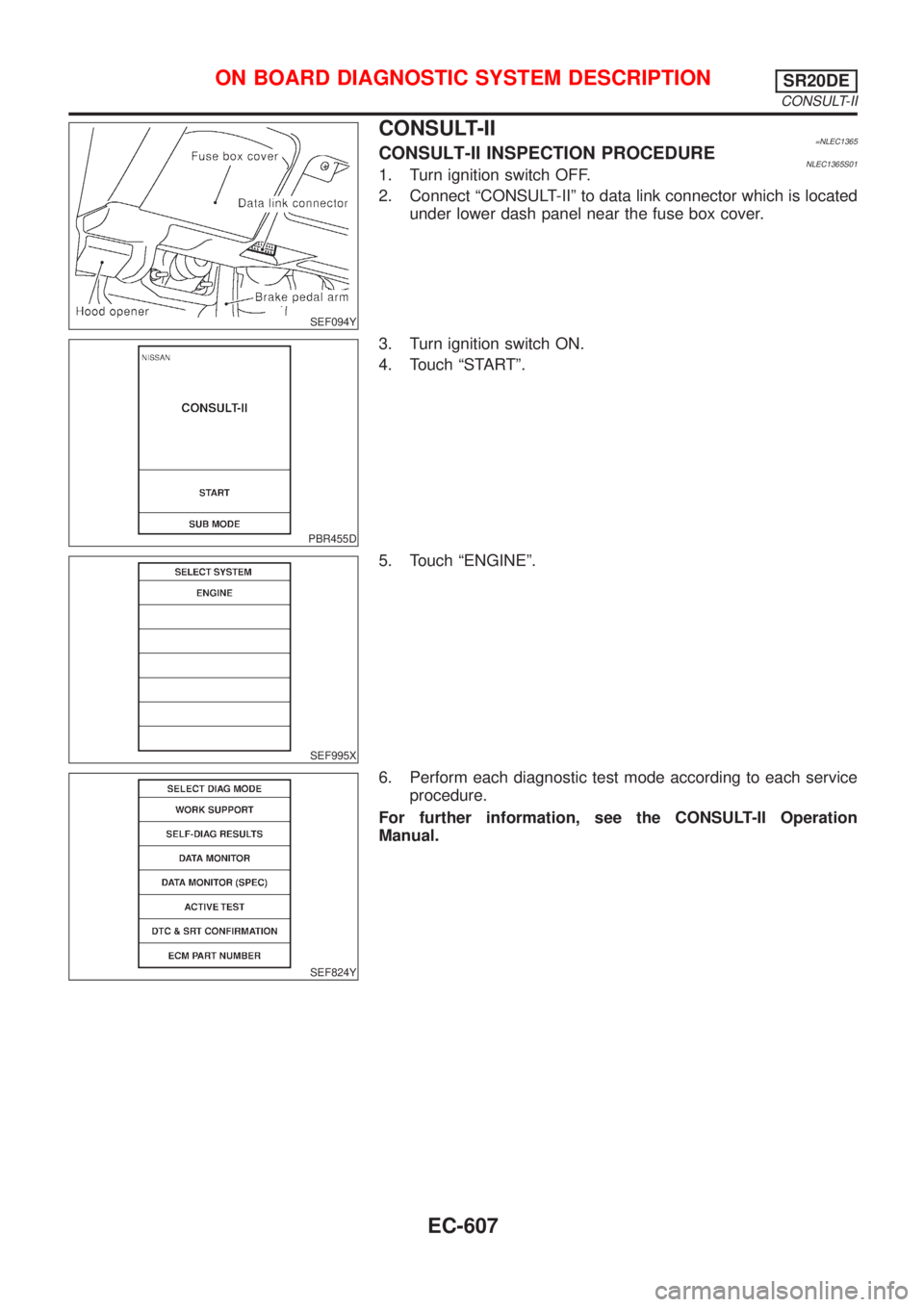
CONSULT-II=NLEC1365CONSULT-II INSPECTION PROCEDURENLEC1365S011. Turn ignition switch OFF.
2. Connect ªCONSULT-IIº to data link connector which is located
under lower dash panel near the fuse box cover.
PBR455D
3. Turn ignition switch ON.
4. Touch ªSTARTº.
SEF995X
5. Touch ªENGINEº.
SEF824Y
6. Perform each diagnostic test mode according to each service
procedure.
For further information, see the CONSULT-II Operation
Manual.
ON BOARD DIAGNOSTIC SYSTEM DESCRIPTIONSR20DE
CONSULT-II
EC-607
Page 1042 of 3051
SEF139P
Generic Scan Tool (GST)=NLEC1366DESCRIPTIONNLEC1366S01Generic Scan Tool (OBDII scan tool) complying with ISO 15031-4
has 9 different functions explained on the next page.
ISO 9141 is used as the protocol.
The name ªGSTº or ªGeneric Scan Toolº is used in this service
manual.
SEF094Y
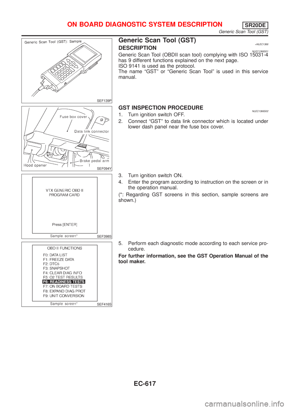
GST INSPECTION PROCEDURENLEC1366S021. Turn ignition switch OFF.
2. Connect ªGSTº to data link connector which is located under
lower dash panel near the fuse box cover.
SEF398S
3. Turn ignition switch ON.
4. Enter the program according to instruction on the screen or in
the operation manual.
(*: Regarding GST screens in this section, sample screens are
shown.)
SEF416S
5. Perform each diagnostic mode according to each service pro-
cedure.
For further information, see the GST Operation Manual of the
tool maker.
ON BOARD DIAGNOSTIC SYSTEM DESCRIPTIONSR20DE
Generic Scan Tool (GST)
EC-617
Page 1310 of 3051
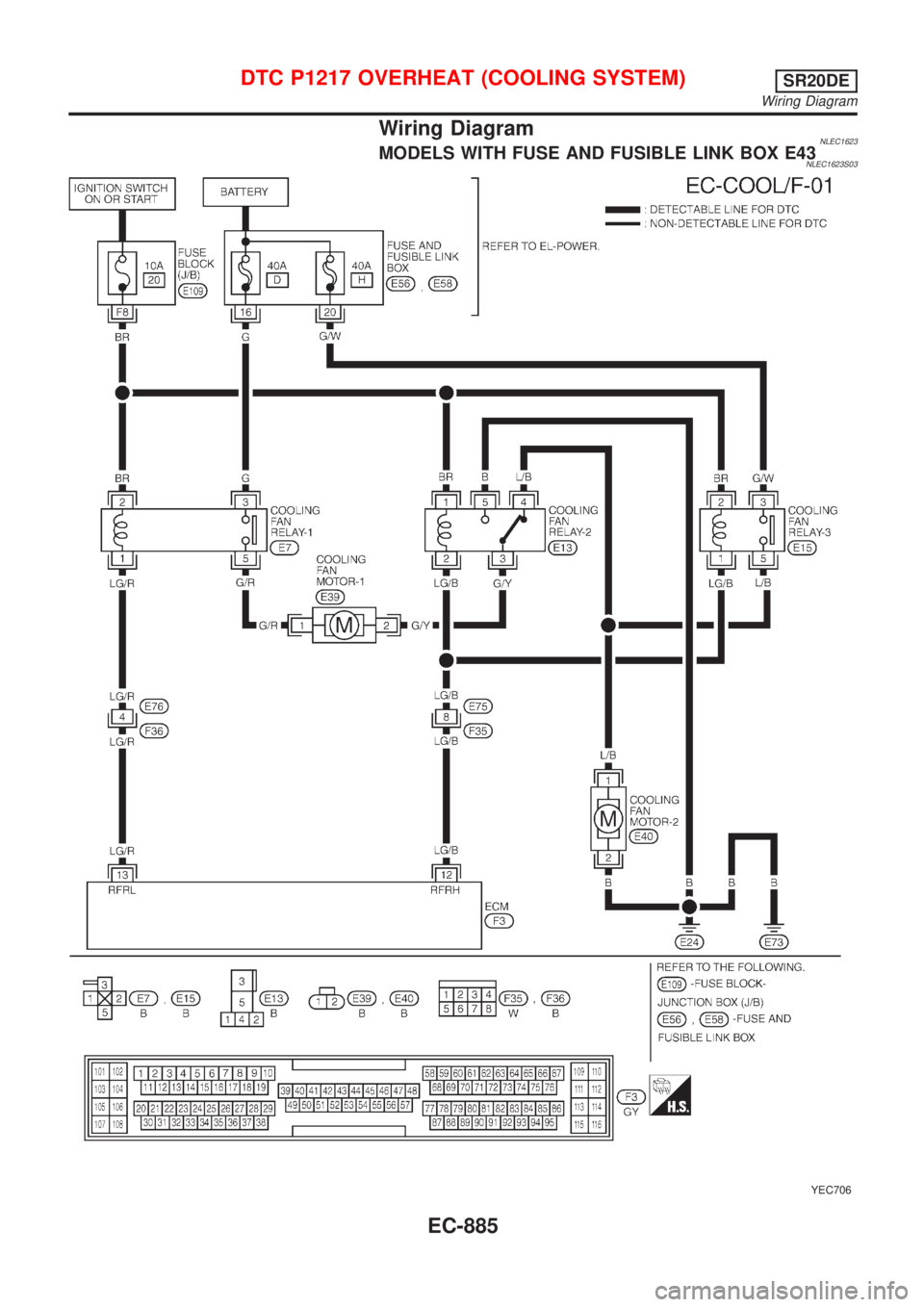
Wiring DiagramNLEC1623MODELS WITH FUSE AND FUSIBLE LINK BOX E43NLEC1623S03
YEC706
DTC P1217 OVERHEAT (COOLING SYSTEM)SR20DE
Wiring Diagram
EC-885
Page 1311 of 3051
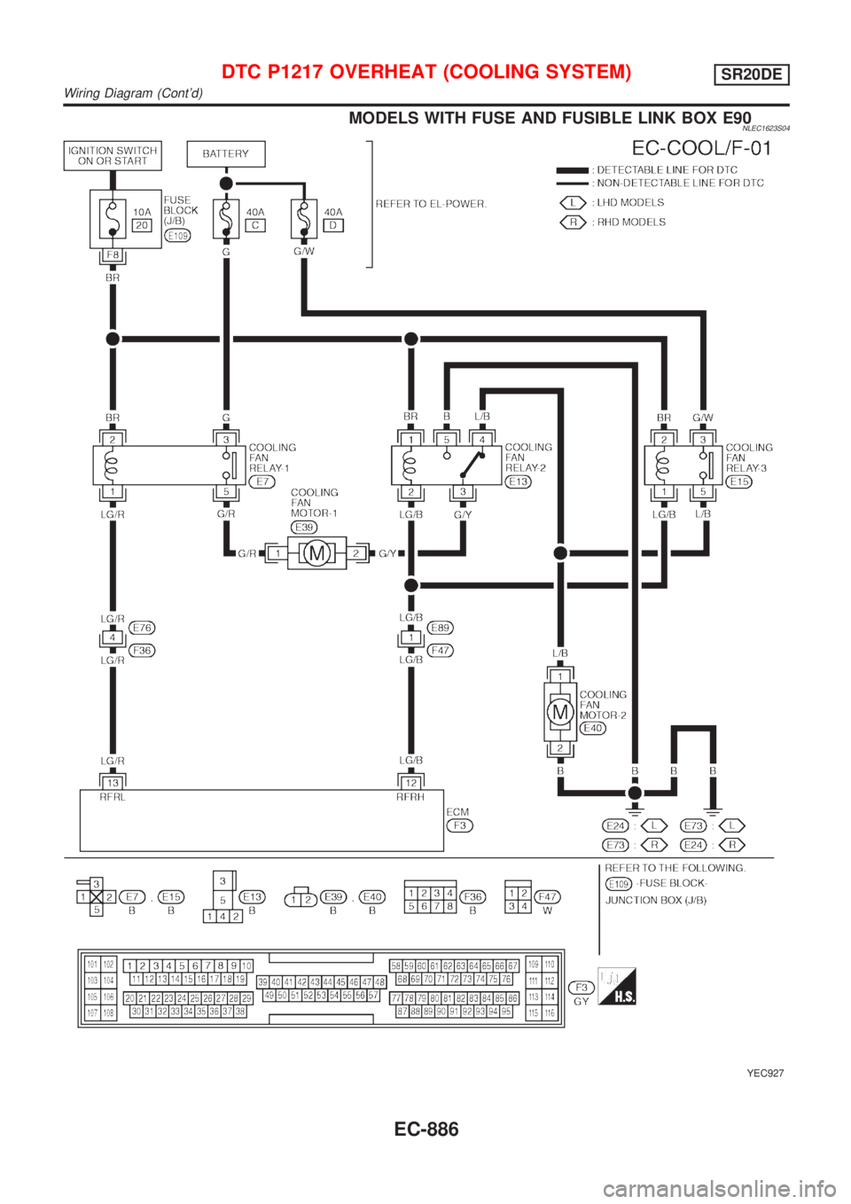
MODELS WITH FUSE AND FUSIBLE LINK BOX E90NLEC1623S04
YEC927
DTC P1217 OVERHEAT (COOLING SYSTEM)SR20DE
Wiring Diagram (Cont'd)
EC-886
Page 1629 of 3051
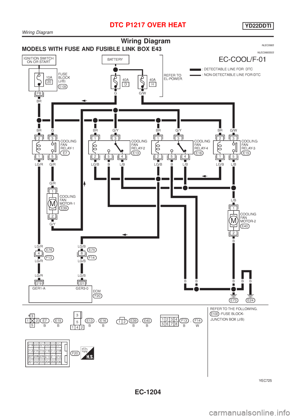
Wiring DiagramNLEC0665MODELS WITH FUSE AND FUSIBLE LINK BOX E43NLEC0665S03
YEC725
DTC P1217 OVER HEATYD22DDTI
Wiring Diagram
EC-1204
