accelerator control NISSAN ALMERA TINO 2001 Service User Guide
[x] Cancel search | Manufacturer: NISSAN, Model Year: 2001, Model line: ALMERA TINO, Model: NISSAN ALMERA TINO 2001Pages: 3051, PDF Size: 46.38 MB
Page 561 of 3051

TERMI-
NAL
NO.WIRE
COLORITEM CONDITION DATA (DC Voltage)
14 GY/LEVAP canister purge
volume control valve
(ON/OFF duty)[Engine is running]
+Warm-up condition
+Accelerator pedal depressed5 - 12V
SEF975W
21 B/P Fuel pump relay[Ignition switch ªONº]
+For 1 second after turning ignition switch ªONº
[Engine is running]0-1V
[Ignition switch ªONº]
+More than 1 second after turning ignition
switch ªONºBATTERY VOLTAGE
(11 - 14V)
22 OR/L Malfunction indicator[Ignition switch ªONº]0-1V
[Engine is running]
+Idle speedBATTERY VOLTAGE
(11 - 14V)
23 L Air conditioner relay[Engine is running]
+Both A/C switch and blower switch are ªONºApproximately 0V
[Engine is running]
+A/C switch is ªOFFºBATTERY VOLTAGE
(11 - 14V)
31 W/GECM relay (Self shut-
off)[Ignition switch ªOFFº]
+For 9 seconds after turning ignition switch
ªOFFº0-1V
[Ignition switch ªOFFº]
+9 seconds passed after turning ignition switch
ªOFFºBATTERY VOLTAGE
(11 - 14V)
32 L/OR Tachometer[Engine is running]
+Warm-up condition
+Idle speed7-8V
SEF928X
[Engine is running]
+Engine speed is 2,000 rpm7-8V
SEF929X
TROUBLE DIAGNOSIS Ð GENERAL DESCRIPTIONQG18DE
ECM Terminals and Reference Value (Cont'd)
EC-136
Page 600 of 3051

Component DescriptionNLEC0079NOTE:
If DTC P0120 (0120) is displayed with DTC P0510 (0510), first perform trouble diagnosis for DTC P0510,
EC-352.
The throttle position sensor responds to the accelerator pedal movement. This sensor is a kind of potentiom-
eter which transforms the throttle position into output voltage, and emits the voltage signal to the ECM. In
addition, the sensor detects the opening and closing speed of the throttle valve and feeds the voltage signal
to the ECM.
Idle position of the throttle valve is determined by the ECM receiving the signal from the throttle position sen-
sor. This sensor controls engine operation such as fuel cut. On the other hand, the ªWide open and closed
throttle position switchº, which is built into the throttle position sensor unit, is not used for engine control.
NEF308A
CONSULT-II Reference Value in Data Monitor
Mode
NLEC0080Specification data are reference values.
MONITOR ITEM CONDITION SPECIFICATION
THRTL POS SEN+Engine: Idle Throttle valve: fully closed 0.15 - 0.85V
+Ignition switch: ON
(Engine stopped)Throttle valve: fully opened 3.5 - 4.7V
ABSOL TH´P/S+Engine: Idle Throttle valve: fully closed 0.0É
+Ignition switch: ON
(Engine stopped)Throttle valve: fully opened Approx. 80É
DTC P0120 THROTTLE POSITION SENSORQG18DE
Component Description
EC-175
Page 694 of 3051

On Board Diagnosis LogicNLEC0188With the Air/Fuel Mixture Ratio Self-Learning Control, the actual mixture ratio can be brought closely to the
theoretical mixture ratio based on the mixture ratio feedback signal from the heated oxygen sensor 1 (front).
The ECM calculates the necessary compensation to correct the offset between the actual and the theoretical
ratios.
In case the amount of the compensation value is extremely large (The actual mixture ratio is too lean.), the
ECM judges the condition as the fuel injection system malfunction and lights up the MIL (2 trip detection logic).
Sensor Input Signal to ECM ECM function Actuator
Heated oxygen sensor 1 (front)Density of oxygen in exhaust gas
(Mixture ratio feedback signal)Fuel injection & mixture
ratio controlInjectors
DTC No. Malfunction is detected when ... Check Items (Possible Cause)
P0171
0171+Fuel injection system does not operate properly.
+The amount of mixture ratio compensation is too large.
(The mixture ratio is too lean.)+Intake air leaks
+Heated oxygen sensor 1 (front)
+Injectors
+Exhaust gas leaks
+Incorrect fuel pressure
+Lack of fuel
+Mass air flow sensor
SEF652Y
SEF058Y
DTC Confirmation ProcedureNLEC0189NOTE:
If ªDTC Confirmation Procedureº has been previously conducted,
always turn ignition switch ªOFFº and wait at least 9 seconds
before conducting the next test.
With CONSULT-II
1) Start engine and warm it up to normal operating temperature.
2) Turn ignition switch ªOFFº and wait at least 9 seconds.
3) Turn ignition switch ªONº and select ªSELF-LEARN CON-
TROLº in ªWORK SUPPORTº mode with CONSULT-II.
4) Clear the self-learning control coefficient by touching ªSTARTº.
5) Select ªDATA MONITORº mode with CONSULT-II.
6) Start engine again and let it idle for at least 10 minutes.
The 1st trip DTC P0171 should be detected at this stage, if a
malfunction exists. If so, go to ªDiagnostic Procedureº,
EC-273.
7) If it is difficult to start engine at step 6, the fuel injection sys-
tem has a malfunction.
8) Crank engine while depressing accelerator pedal. If engine
starts, go to ªDiagnostic Procedureº, EC-273. If engine does
not start, visually check for exhaust and intake air leak.
JEF105Y
With GST
1) Start engine and warm it up to normal operating temperature.
2) Turn ignition switch ªOFFº and wait at least 9 seconds.
3) Disconnect mass air flow sensor harness connector. Then
restart and run engine for at least 3 seconds at idle speed.
4) Stop engine and reconnect mass air flow sensor harness con-
nector.
5) Select ªMODE 7º with GST. Make sure 1st trip DTC P0100 is
detected.
6) Select ªMODE 4º with GST and erase the 1st trip DTC P0100.
DTC P0171 FUEL INJECTION SYSTEM FUNCTION
(LEAN SIDE)
QG18DE
On Board Diagnosis Logic
EC-269
Page 702 of 3051

On Board Diagnosis LogicNLEC0192With the Air/Fuel Mixture Ratio Self-Learning Control, the actual mixture ratio can be brought closely to the
theoretical mixture ratio based on the mixture ratio feedback signal from the heated oxygen sensor 1 (front).
The ECM calculates the necessary compensation to correct the offset between the actual and the theoretical
ratios.
In case the amount of the compensation value is extremely large (The actual mixture ratio is too rich.), the
ECM judges the condition as the fuel injection system malfunction and lights up the MI (2 trip detection logic).
Sensor Input Signal to ECMECM func-
tionActuator
Heated oxygen sensor 1 (front)Density of oxygen in exhaust gas
(Mixture ratio feedback signal)Fuel injec-
tion & mix-
ture ratio
controlInjectors
DTC No. Malfunction is detected when ... Check Items (Possible Cause)
P0172
0172+Fuel injection system does not operate properly.
+The amount of mixture ratio compensation is too large.
(The mixture ratio is too rich.)+Heated oxygen sensor 1 (front)
+Injectors
+Exhaust gas leaks
+Incorrect fuel pressure
+Mass air flow sensor
SEF652Y
SEF058Y
DTC Confirmation ProcedureNLEC0193NOTE:
If ªDTC Confirmation Procedureº has been previously conducted,
always turn ignition switch ªOFFº and wait at least 9 seconds
before conducting the next test.
With CONSULT-II
1) Start engine and warm it up to normal operating temperature.
2) Turn ignition switch ªOFFº and wait at least 9 seconds.
3) Turn ignition switch ªONº and select ªSELF-LEARN CON-
TROLº in ªWORK SUPPORTº mode with CONSULT-II.
4) Clear the self-learning control coefficient by touching ªSTARTº.
5) Select ªDATA MONITORº mode with CONSULT-II.
6) Start engine again and let it idle for at least 10 minutes.
The 1st trip DTC P0172 should be detected at this stage, if a
malfunction exists. If so, go to ªDiagnostic Procedureº,
EC-281.
7) If it is difficult to start engine at step 6, the fuel injection sys-
tem has a malfunction.
8) Crank engine while depressing accelerator pedal. If engine
starts, go to ªDiagnostic Procedureº, EC-281. If engine does
not start, remove ignition plugs and check for fouling, etc.
JEF105Y
With GST
1) Start engine and warm it up to normal operating temperature.
2) Turn ignition switch ªOFFº and wait at least 9 seconds.
3) Disconnect mass air flow sensor harness connector. Then
restart and run engine for at least 3 seconds at idle speed.
4) Stop engine and reconnect mass air flow sensor harness con-
nector.
5) Select ªMODE 7º with GST. Make sure 1st trip DTC P0100 is
detected.
6) Select ªMODE 4º with GST and erase the 1st trip DTC P0100.
DTC P0172 FUEL INJECTION SYSTEM FUNCTION
(RICH SIDE)
QG18DE
On Board Diagnosis Logic
EC-277
Page 777 of 3051

SEF505V
Component DescriptionNLEC0287A closed throttle position switch and wide open throttle position
switch are built into the throttle position sensor unit. The wide open
throttle position switch is not used.
When the throttle valve is in the closed position, the closed throttle
position switch sends a voltage signal to the ECM. The ECM only
uses this signal to open or close the EVAP canister purge control
valve when the throttle position sensor is malfunctioning.
CONSULT-II Reference Value in Data Monitor
Mode
NLEC0571Specification data are reference values.
MONITOR ITEM CONDITION SPECIFICATION
CLSD THL/P SW+Engine: IdleThrottle valve: Idle position ON
Throttle valve: Slightly open OFF
ECM Terminals and Reference ValueNLEC0288Specification data are reference values and are measured between each terminal and ground.
CAUTION:
Do not use ECM ground terminals when measuring input/output voltage. Doing so may result in dam-
age to the ECM's transistor. Use a ground other than ECM terminals, such as the ground.
TER-
MINAL
NO.WIRE
COLORITEM CONDITION DATA (DC Voltage)
40 Y/PUThrottle position switch
(Closed position)[Engine is running]
+Accelerator pedal releasedBATTERY VOLTAGE
(11 - 14V)
[Engine is running]
+Accelerator pedal depressedApproximately 0V
On Board Diagnosis LogicNLEC0289
DTC No. Malfunction is detected when ... Check Items (Possible Cause)
P0510
0510+Battery voltage from the closed throttle position switch is
sent to ECM with the throttle valve opened.+Harness or connectors
(The closed throttle position switch circuit is
shorted.)
+Closed throttle position switch
+Throttle position sensor
SEF197Y
DTC Confirmation ProcedureNLEC0290CAUTION:
Always drive vehicle at a safe speed.
NOTE:
If ªDTC Confirmation Procedureº has been previously conducted,
always turn ignition switch ªOFFº and wait at least 9 seconds
before conducting the next test.
With CONSULT-II
1) Start engine and warm it up to normal operating temperature.
2) Turn ignition switch ªOFFº, wait at least 9 seconds and then
start engine.
DTC P0510 CLOSED THROTTLE POSITION SWITCH
(WHERE FITTED)
QG18DE
Component Description
EC-352
Page 791 of 3051

DescriptionNLEC0522SYSTEM DESCRIPTIONNLEC0522S01
Sensor Input Signal to ECMECM func-
tionActuator
Throttle position sensor Throttle position
Swirl con-
trol valve
system
controlSwirl control valve control sole-
noid valve via swirl control
valve Ignition switch Start signal
Crankshaft position sensor (POS) Engine speed
Camshaft position sensor (PHASE) Engine speed and cylinder number
Mass air flow sensor Amount of intake air
Engine coolant temperature sensor Engine coolant temperature
This system has a swirl control valve in the intake passage of each cylinder.
While idling and during low engine speed operation, the swirl control valve closes. Thus the velocity of the air
in the intake passage increases, promoting the vaporization of the fuel and producing a swirl in the combus-
tion chamber.
Because of this operation, this system tends to increase the burning speed of the gas mixture, improve fuel
consumption, and increase the stability in running conditions.
Also, except when idling and during low engine speed operation, this system opens the swirl control valve.
The solenoid valve controls swirl control valve's shut/open condition. This solenoid valve is operated by the
ECM.
OPERATIONNLEC0522S02
Engine coolant tempera-
tureThrottle position sensor
(Idle position)Engine speedSwirl control valve con-
trol solenoid valveSwirl control valve
15 - 40ÉC
(59 - 104ÉF)ON Ð
ON Closed
OFF Below 2,400 rpm*
Except above OFF Open
*: The value may vary according to accelerator pedal operation.
SEF081X
CONSULT-II Reference Value in Data Monitor
Mode
NLEC0523Specification data are reference values.
MONITOR ITEM CONDITION SPECIFICATION
SWRL CONT S/V+Engine speed: IdleEngine coolant temperature is
between 15ÉC (59ÉF) to 40ÉC
(104ÉF).ON
Engine coolant temperature is
above 40ÉC (104ÉF).OFF
DTC P1131 SWIRL CONTROL VALVE SOLENOID VALVE (CIRCUIT)
(WHERE FITTED)
QG18DE
Description
EC-366
Page 906 of 3051

DescriptionNLEC1248SYSTEM DESCRIPTIONNLEC1248S01
Sensor Input Signal to ECMECM func-
tionActuator
Throttle position sensor Throttle position
Swirl con-
trol valve
system
controlSwirl control valve control sole-
noid valve via swirl control
valve Ignition switch Start signal
Crankshaft position sensor (POS) Engine speed
Camshaft position sensor (PHASE) Engine speed and cylinder number
Mass air flow sensor Amount of intake air
Engine coolant temperature sensor Engine coolant temperature
This system has a swirl control valve in the intake passage of each cylinder.
While idling and during low engine speed operation, the swirl control valve closes. Thus the velocity of the air
in the intake passage increases, promoting the vaporization of the fuel and producing a swirl in the combus-
tion chamber.
Because of this operation, this system tends to increase the burning speed of the gas mixture, improve fuel
consumption, and increase the stability in running conditions.
Also, except when idling and during low engine speed operation, this system opens the swirl control valve.
The solenoid valve controls swirl control valve's shut/open condition. This solenoid valve is operated by the
ECM.
OPERATIONNLEC1248S02
Engine coolant tempera-
tureThrottle position sensor
(Idle position)Engine speedSwirl control valve con-
trol solenoid valveSwirl control valve
15 - 40ÉC
(59 - 104ÉF)ON Ð
ON Closed
OFF Below 2,400 rpm*
Except above OFF Open
*: The value may vary according to accelerator pedal operation.
SEF081X
CONSULT-II Reference Value in Data Monitor
Mode
NLEC1249Specification data are reference values.
MONITOR ITEM CONDITION SPECIFICATION
SWRL CONT S/V+Engine speed: IdleEngine coolant temperature is
between 15ÉC (59ÉF) to 40ÉC
(104ÉF).ON
Engine coolant temperature is
above 40ÉC (104ÉF).OFF
SWIRL CONTROL VALVE CONTROL SYSTEM
(WHERE FITTED)
QG18DE
Description
EC-481
Page 997 of 3051
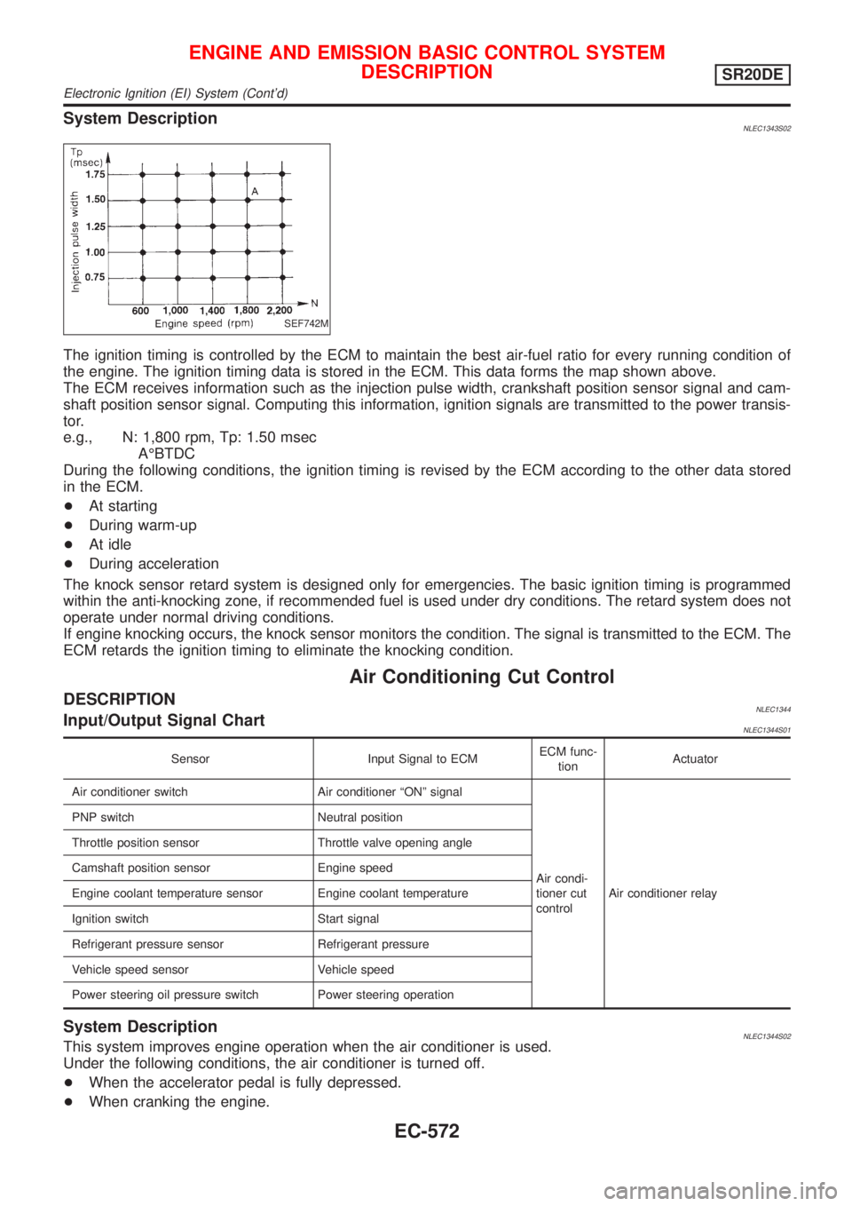
System DescriptionNLEC1343S02
SEF742M
The ignition timing is controlled by the ECM to maintain the best air-fuel ratio for every running condition of
the engine. The ignition timing data is stored in the ECM. This data forms the map shown above.
The ECM receives information such as the injection pulse width, crankshaft position sensor signal and cam-
shaft position sensor signal. Computing this information, ignition signals are transmitted to the power transis-
tor.
e.g., N: 1,800 rpm, Tp: 1.50 msec
AÉBTDC
During the following conditions, the ignition timing is revised by the ECM according to the other data stored
in the ECM.
+At starting
+During warm-up
+At idle
+During acceleration
The knock sensor retard system is designed only for emergencies. The basic ignition timing is programmed
within the anti-knocking zone, if recommended fuel is used under dry conditions. The retard system does not
operate under normal driving conditions.
If engine knocking occurs, the knock sensor monitors the condition. The signal is transmitted to the ECM. The
ECM retards the ignition timing to eliminate the knocking condition.
Air Conditioning Cut Control
DESCRIPTIONNLEC1344Input/Output Signal ChartNLEC1344S01
Sensor Input Signal to ECMECM func-
tionActuator
Air conditioner switch Air conditioner ªONº signal
Air condi-
tioner cut
controlAir conditioner relay PNP switch Neutral position
Throttle position sensor Throttle valve opening angle
Camshaft position sensor Engine speed
Engine coolant temperature sensor Engine coolant temperature
Ignition switch Start signal
Refrigerant pressure sensor Refrigerant pressure
Vehicle speed sensor Vehicle speed
Power steering oil pressure switch Power steering operation
System DescriptionNLEC1344S02This system improves engine operation when the air conditioner is used.
Under the following conditions, the air conditioner is turned off.
+When the accelerator pedal is fully depressed.
+When cranking the engine.
ENGINE AND EMISSION BASIC CONTROL SYSTEM
DESCRIPTION
SR20DE
Electronic Ignition (EI) System (Cont'd)
EC-572
Page 1003 of 3051

If results are unsatisfactory, perform Fuel Pressure Regulator
Check, EC-578.
SEF718B
Fuel Pressure Regulator CheckNLEC13531. Stop engine and disconnect fuel pressure regulator vacuum
hose from intake manifold collector.
2. Plug intake manifold collector with a rubber cap.
3. Connect variable vacuum source to fuel pressure regulator.
4. Start engine and read indication of fuel pressure gauge as
vacuum is changed.
Fuel pressure should decrease as vacuum increases. If results
are unsatisfactory, replace fuel pressure regulator.
Injector
REMOVAL AND INSTALLATIONNLEC1746
SEF324Z
1. Release fuel pressure to zero.
2. Remove accelerator wire bracket.
3. Remove EVAP canister purge volume control solenoid valve
and the bracket.
BASIC SERVICE PROCEDURESR20DE
Fuel Pressure Regulator Check
EC-578
Page 1125 of 3051

Component DescriptionNLEC1404NOTE:
If DTC P0120 (0120) is displayed with DTC P0510 (0510), first perform trouble diagnosis for DTC P0510,
EC-872.
The throttle position sensor responds to the accelerator pedal movement. This sensor is a kind of potentiom-
eter which transforms the throttle position into output voltage, and emits the voltage signal to the ECM. In
addition, the sensor detects the opening and closing speed of the throttle valve and feeds the voltage signal
to the ECM.
Idle position of the throttle valve is determined by the ECM receiving the signal from the throttle position sen-
sor. This sensor controls engine operation such as fuel cut. On the other hand, the ªWide open and closed
throttle position switchº, which is built into the throttle position sensor unit, is not used for engine control.
SEF208W
CONSULT-II Reference Value in Data Monitor
Mode
NLEC1405Specification data are reference values.
MONITOR ITEM CONDITION SPECIFICATION
THRTL POS SEN+Engine: Idle Throttle valve: fully closed 0.15 - 0.85V
+Ignition switch: ON
(Engine stopped)Throttle valve: fully opened 3.5 - 4.7V
ABSOL TH´P/S+Engine: Idle Throttle valve: fully closed 0.0É
+Ignition switch: ON
(Engine stopped)Throttle valve: fully opened Approx. 80É
DTC P0120 THROTTLE POSITION SENSORSR20DE
Component Description
EC-700