brake rotor NISSAN ALMERA TINO 2001 Service User Guide
[x] Cancel search | Manufacturer: NISSAN, Model Year: 2001, Model line: ALMERA TINO, Model: NISSAN ALMERA TINO 2001Pages: 3051, PDF Size: 46.38 MB
Page 265 of 3051
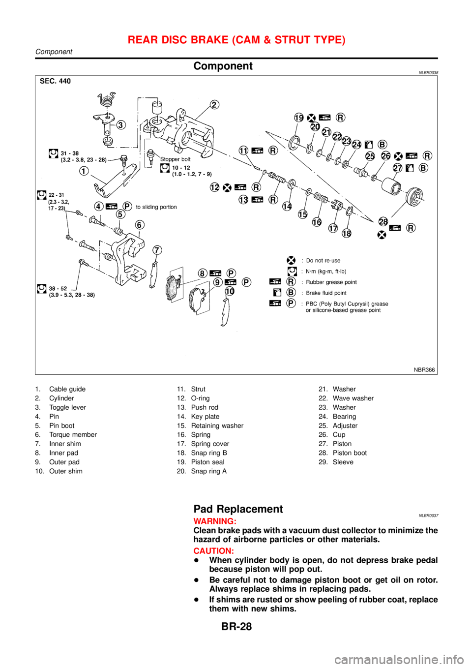
ComponentNLBR0038
NBR366
1. Cable guide
2. Cylinder
3. Toggle lever
4. Pin
5. Pin boot
6. Torque member
7. Inner shim
8. Inner pad
9. Outer pad
10. Outer shim11. Strut
12. O-ring
13. Push rod
14. Key plate
15. Retaining washer
16. Spring
17. Spring cover
18. Snap ring B
19. Piston seal
20. Snap ring A21. Washer
22. Wave washer
23. Washer
24. Bearing
25. Adjuster
26. Cup
27. Piston
28. Piston boot
29. Sleeve
Pad ReplacementNLBR0037WARNING:
Clean brake pads with a vacuum dust collector to minimize the
hazard of airborne particles or other materials.
CAUTION:
+When cylinder body is open, do not depress brake pedal
because piston will pop out.
+Be careful not to damage piston boot or get oil on rotor.
Always replace shims in replacing pads.
+If shims are rusted or show peeling of rubber coat, replace
them with new shims.
REAR DISC BRAKE (CAM & STRUT TYPE)
Component
BR-28
Page 266 of 3051
+It is not necessary to remove connecting bolt except for
disassembly or replacement of caliper assembly. In this
case, suspend cylinder body with wire so as not to stretch
brake hose.
+Burnish the brake contact surfaces after refinishing or
replacing rotors, after replacing pads, or if a soft pedal
occurs at very low mileage.
Refer to“Brake Burnishing Procedure”,“ON-VEHICLE
SERVICE”, BR-7.
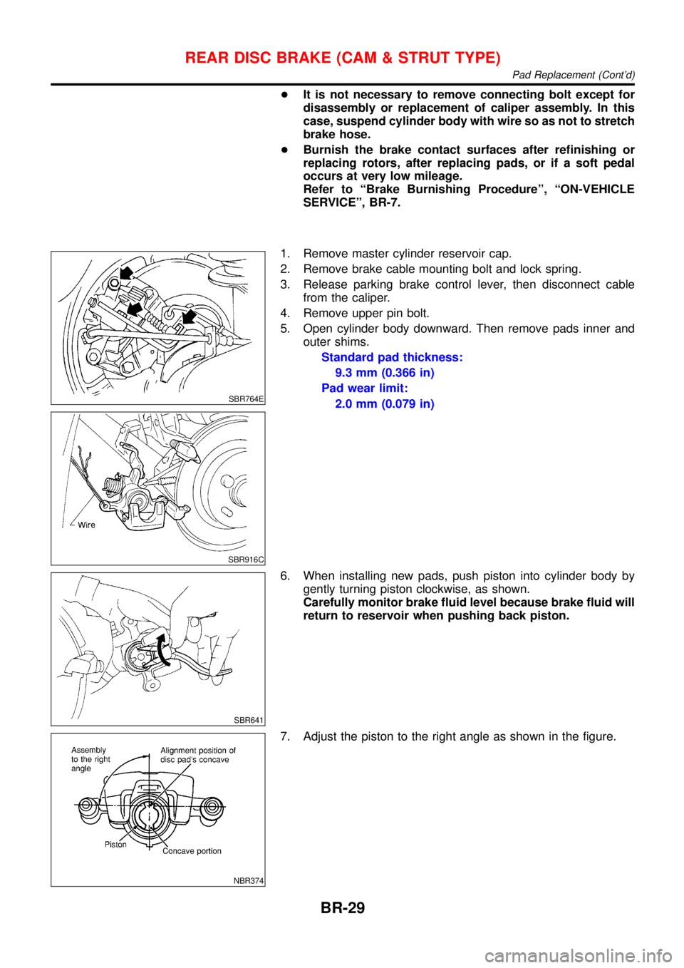
SBR764E
SBR916C
1. Remove master cylinder reservoir cap.
2. Remove brake cable mounting bolt and lock spring.
3. Release parking brake control lever, then disconnect cable
from the caliper.
4. Remove upper pin bolt.
5. Open cylinder body downward. Then remove pads inner and
outer shims.
Standard pad thickness:
9.3 mm (0.366 in)
Pad wear limit:
2.0 mm (0.079 in)
SBR641
6. When installing new pads, push piston into cylinder body by
gently turning piston clockwise, as shown.
Carefully monitor brake fluid level because brake fluid will
return to reservoir when pushing back piston.
NBR374
7. Adjust the piston to the right angle as shown in the figure.
REAR DISC BRAKE (CAM & STRUT TYPE)
Pad Replacement (Cont’d)
BR-29
Page 269 of 3051
Pin and Pin BootNLBR0041S0104Check for wear, cracks or other damage.
Replace if any of the above conditions are observed.
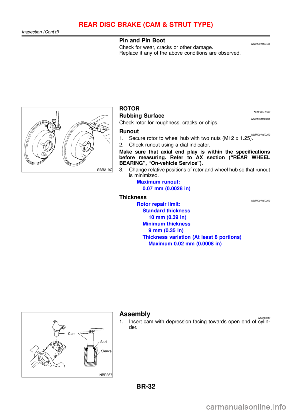
SBR219C
ROTORNLBR0041S02Rubbing SurfaceNLBR0041S0201Check rotor for roughness, cracks or chips.
RunoutNLBR0041S02021. Secure rotor to wheel hub with two nuts (M12 x 1.25).
2. Check runout using a dial indicator.
Make sure that axial end play is within the specifications
before measuring. Refer to AX section (“REAR WHEEL
BEARING”,“On-vehicle Service”).
3. Change relative positions of rotor and wheel hub so that runout
is minimized.
Maximum runout:
0.07 mm (0.0028 in)
ThicknessNLBR0041S0203Rotor repair limit:
Standard thickness
10 mm (0.39 in)
Minimum thickness
9 mm (0.35 in)
Thickness variation (At least 8 portions)
Maximum 0.02 mm (0.0008 in)
NBR367
AssemblyNLBR00421. Insert cam with depression facing towards open end of cylin-
der.
REAR DISC BRAKE (CAM & STRUT TYPE)
Inspection (Cont’d)
BR-32
Page 273 of 3051
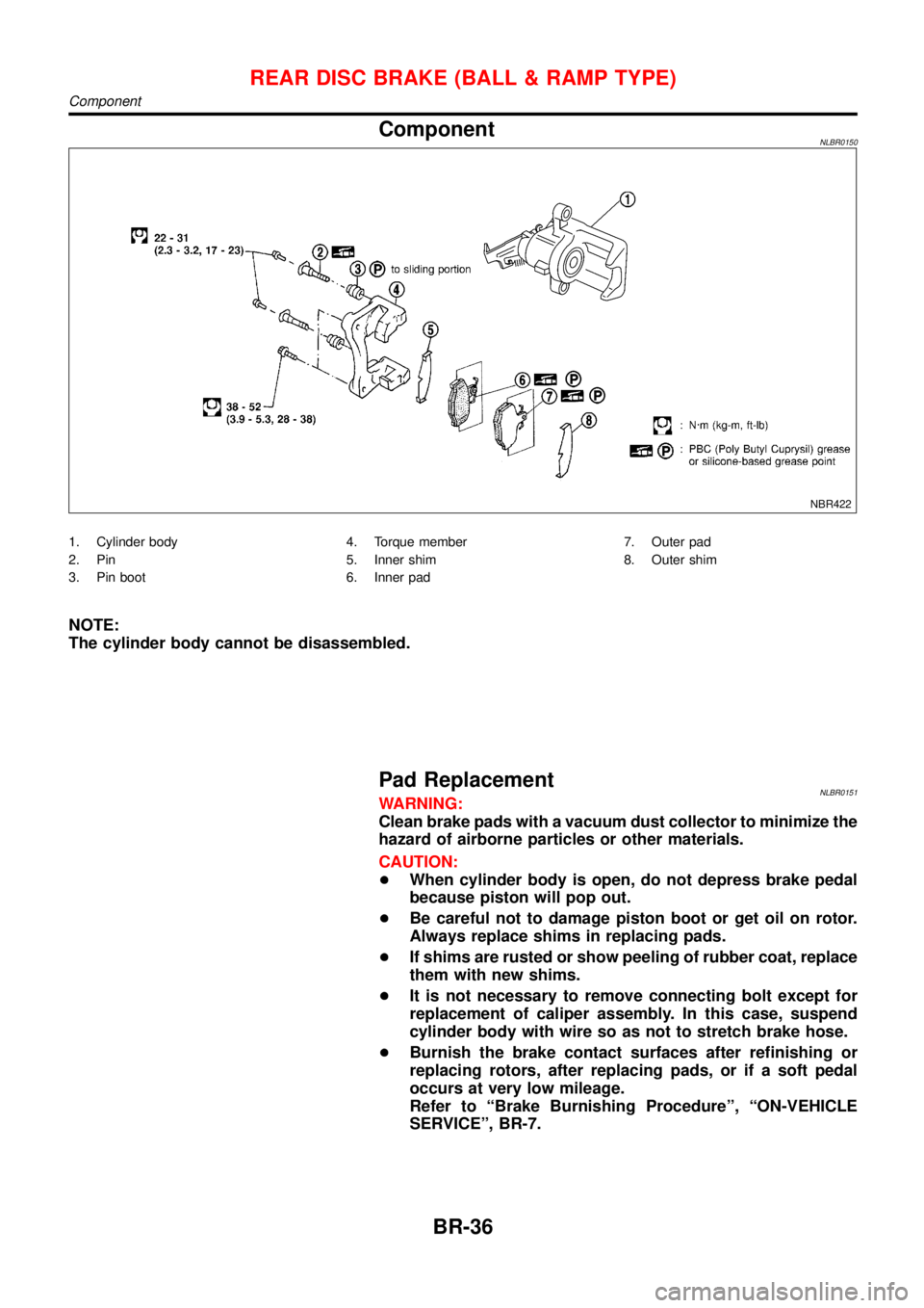
ComponentNLBR0150
NBR422
1. Cylinder body
2. Pin
3. Pin boot4. Torque member
5. Inner shim
6. Inner pad7. Outer pad
8. Outer shim
NOTE:
The cylinder body cannot be disassembled.
Pad ReplacementNLBR0151WARNING:
Clean brake pads with a vacuum dust collector to minimize the
hazard of airborne particles or other materials.
CAUTION:
+When cylinder body is open, do not depress brake pedal
because piston will pop out.
+Be careful not to damage piston boot or get oil on rotor.
Always replace shims in replacing pads.
+If shims are rusted or show peeling of rubber coat, replace
them with new shims.
+It is not necessary to remove connecting bolt except for
replacement of caliper assembly. In this case, suspend
cylinder body with wire so as not to stretch brake hose.
+Burnish the brake contact surfaces after refinishing or
replacing rotors, after replacing pads, or if a soft pedal
occurs at very low mileage.
Refer to“Brake Burnishing Procedure”,“ON-VEHICLE
SERVICE”, BR-7.
REAR DISC BRAKE (BALL & RAMP TYPE)
Component
BR-36
Page 276 of 3051
SBR219C
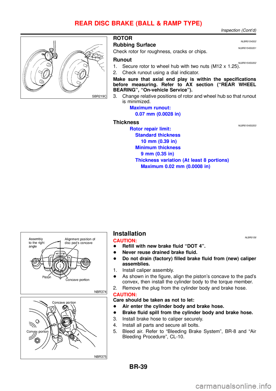
ROTORNLBR0154S02Rubbing SurfaceNLBR0154S0201Check rotor for roughness, cracks or chips.
RunoutNLBR0154S02021. Secure rotor to wheel hub with two nuts (M12 x 1.25).
2. Check runout using a dial indicator.
Make sure that axial end play is within the specifications
before measuring. Refer to AX section (“REAR WHEEL
BEARING”,“On-vehicle Service”).
3. Change relative positions of rotor and wheel hub so that runout
is minimized.
Maximum runout:
0.07 mm (0.0028 in)
ThicknessNLBR0154S0203Rotor repair limit:
Standard thickness
10 mm (0.39 in)
Minimum thickness
9 mm (0.35 in)
Thickness variation (At least 8 portions)
Maximum 0.02 mm (0.0008 in)
NBR374
NBR375
InstallationNLBR0156CAUTION:
+Refill with new brake fluid“DOT 4”.
+Never reuse drained brake fluid.
+Do not drain (factory) filled brake fluid from (new) caliper
assemblies.
1. Install caliper assembly.
+As shown in the figure, align the piston’s concave to the pad’s
convex, then install the cylinder body to the torque member.
2. Remove the plug from the cylinder body and brake hose.
CAUTION:
Care should be taken as not to let:
+Air enter the cylinder body and brake hose.
+Brake fluid spill from the cylinder body and brake hose.
3. Install brake hose to caliper securely.
4. Install all parts and secure all bolts.
5. Bleed air. Refer to“Bleeding Brake System”, BR-8 and“Air
Bleeding Procedure”, CL-10.
REAR DISC BRAKE (BALL & RAMP TYPE)
Inspection (Cont’d)
BR-39
Page 278 of 3051
SBR768E
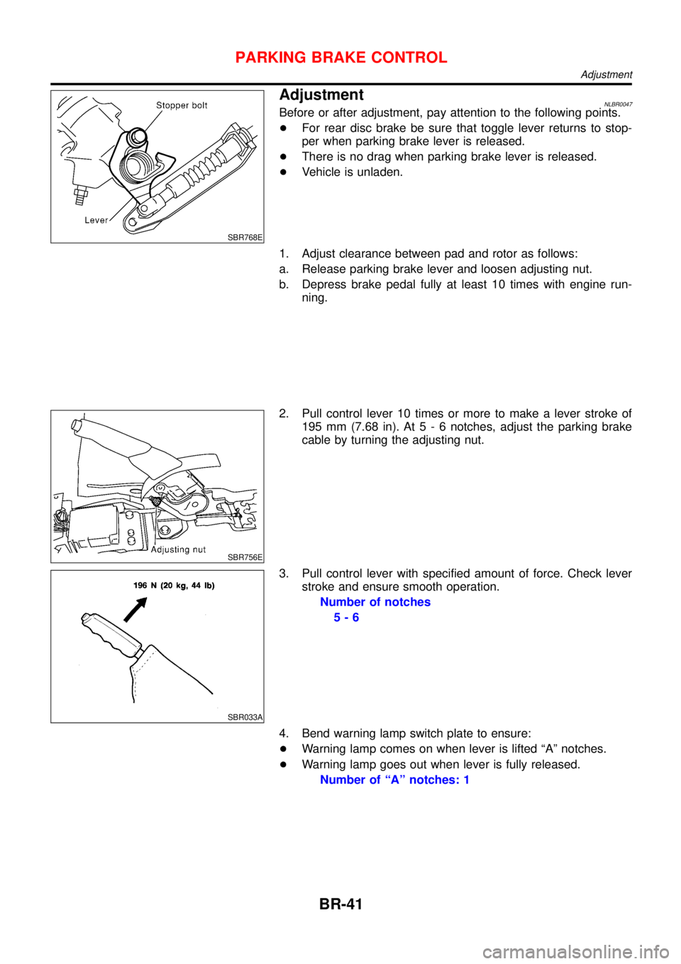
AdjustmentNLBR0047Before or after adjustment, pay attention to the following points.
+For rear disc brake be sure that toggle lever returns to stop-
per when parking brake lever is released.
+There is no drag when parking brake lever is released.
+Vehicle is unladen.
1. Adjust clearance between pad and rotor as follows:
a. Release parking brake lever and loosen adjusting nut.
b. Depress brake pedal fully at least 10 times with engine run-
ning.
SBR756E
2. Pull control lever 10 times or more to make a lever stroke of
195 mm (7.68 in). At5-6notches, adjust the parking brake
cable by turning the adjusting nut.
SBR033A
3. Pull control lever with specified amount of force. Check lever
stroke and ensure smooth operation.
Number of notches
5-6
4. Bend warning lamp switch plate to ensure:
+Warning lamp comes on when lever is lifted“A”notches.
+Warning lamp goes out when lever is fully released.
Number of“A”notches: 1
PARKING BRAKE CONTROL
Adjustment
BR-41
Page 280 of 3051
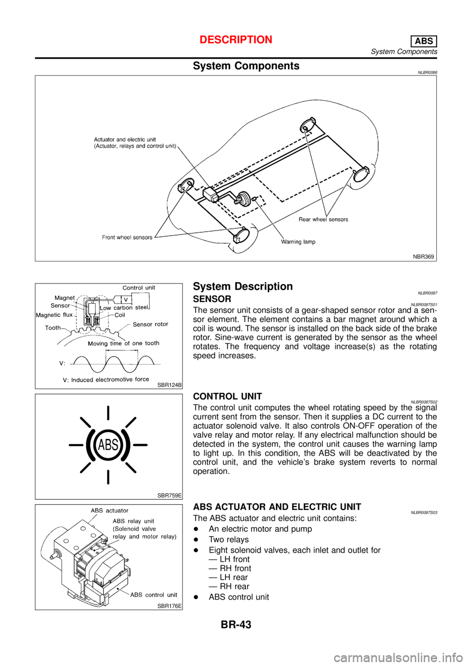
System ComponentsNLBR0086
NBR369
SBR124B
System DescriptionNLBR0087SENSORNLBR0087S01The sensor unit consists of a gear-shaped sensor rotor and a sen-
sor element. The element contains a bar magnet around which a
coil is wound. The sensor is installed on the back side of the brake
rotor. Sine-wave current is generated by the sensor as the wheel
rotates. The frequency and voltage increase(s) as the rotating
speed increases.
SBR759E
CONTROL UNITNLBR0087S02The control unit computes the wheel rotating speed by the signal
current sent from the sensor. Then it supplies a DC current to the
actuator solenoid valve. It also controls ON-OFF operation of the
valve relay and motor relay. If any electrical malfunction should be
detected in the system, the control unit causes the warning lamp
to light up. In this condition, the ABS will be deactivated by the
control unit, and the vehicle’s brake system reverts to normal
operation.
SBR176E
ABS ACTUATOR AND ELECTRIC UNITNLBR0087S03The ABS actuator and electric unit contains:
+An electric motor and pump
+Two relays
+Eight solenoid valves, each inlet and outlet for
—LH front
—RH front
—LH rear
—RH rear
+ABS control unit
DESCRIPTIONABS
System Components
BR-43
Page 303 of 3051

3 CHECK BRAKE BOOSTER OPERATION
Check brake booster for operation and air tightness.
Refer to BR-16.
SBR058C
Is brake booster airtight and functioning properly?
Ye s©GO TO 4.
No©Replace. GO TO 4.
4 CHECK BRAKE PAD AND ROTOR
Check brake pad and rotor.
Refer to BR-24, 26, 28, 32.
SBR059C
Are brake pads and rotors functioning properly?
Ye s©GO TO 5.
No©Replace.
TROUBLE DIAGNOSIS Ð BASIC INSPECTIONABS
Preliminary Check (Cont'd)
BR-66
Page 319 of 3051

1. ABS Works FrequentlyNLBR0104
1 CHECK BRAKE FLUID PRESSURE
Check brake fluid pressure distribution.
Is brake fluid pressure distribution normal?
Ye s©GO TO 2.
No©Perform Preliminary Check. Refer to BR-65.
2 CHECK WHEEL SENSOR
1. Check wheel sensor connector for terminal damage or loose connections.
2. Perform wheel sensor mechanical check.
Refer to ªWheel Sensor or Rotorº, BR-71.
Are wheel sensors functioning properly?
Ye s©GO TO 3.
No©Repair.
3 CHECK FRONT AXLE
Check front and rear axles for excessive looseness. Refer to AX section, ªFront Wheel Bearingº, ªON-VEHICLE SERVICEº
and ªRear Wheel Bearingº, ªON-VEHICLE SERVICEº.
Is front axle installed properly?
Ye s©Go to ª3. CHECK WARNING LAMP INDICATIONº in ª2. Unexpected Pedal Actionº,
BR-82.
No©Repair.
2. Unexpected Pedal ActionNLBR0105
1 CHECK BRAKE PEDAL STROKE
Check brake pedal stroke. Is stroke excessively large?
SBR540A
Ye s©Perform Preliminary Check. Refer to BR-65.
No©GO TO 2.
TROUBLE DIAGNOSES FOR SYMPTOMSABS
1. ABS Works Frequently
BR-82
Page 330 of 3051
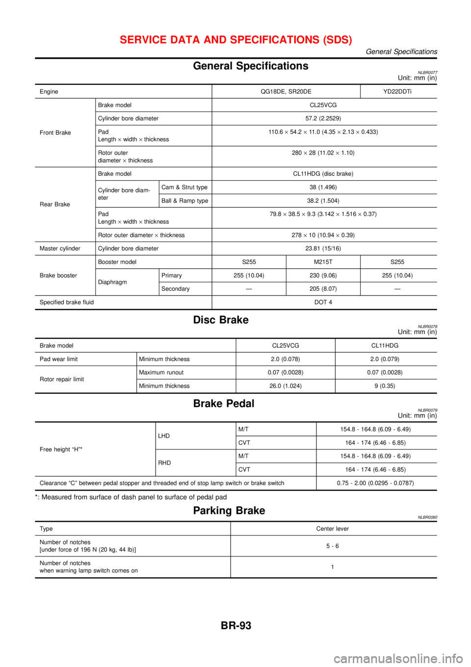
General SpecificationsNLBR0077Unit: mm (in)
EngineQG18DE, SR20DE YD22DDTi
Front BrakeBrake model CL25VCG
Cylinder bore diameter 57.2 (2.2529)
Pad
Length×width×thickness110.6×54.2×11.0 (4.35×2.13×0.433)
Rotor outer
diameter×thickness280×28 (11.02×1.10)
Rear BrakeBrake model CL11HDG (disc brake)
Cylinder bore diam-
eterCam & Strut type 38 (1.496)
Ball & Ramp type 38.2 (1.504)
Pad
Length×width×thickness79.8×38.5×9.3 (3.142×1.516×0.37)
Rotor outer diameter×thickness 278×10 (10.94×0.39)
Master cylinder Cylinder bore diameter 23.81 (15/16)
Brake boosterBooster model S255 M215T S255
DiaphragmPrimary 255 (10.04) 230 (9.06) 255 (10.04)
Secondary—205 (8.07)—
Specified brake fluidDOT 4
Disc BrakeNLBR0078Unit: mm (in)
Brake modelCL25VCG CL11HDG
Pad wear limit Minimum thickness 2.0 (0.078) 2.0 (0.079)
Rotor repair limitMaximum runout 0.07 (0.0028) 0.07 (0.0028)
Minimum thickness 26.0 (1.024) 9 (0.35)
Brake PedalNLBR0079Unit: mm (in)
Free height“H”*LHDM/T 154.8 - 164.8 (6.09 - 6.49)
CVT 164 - 174 (6.46 - 6.85)
RHDM/T 154.8 - 164.8 (6.09 - 6.49)
CVT 164 - 174 (6.46 - 6.85)
Clearance“C”between pedal stopper and threaded end of stop lamp switch or brake switch 0.75 - 2.00 (0.0295 - 0.0787)
*: Measured from surface of dash panel to surface of pedal pad
Parking BrakeNLBR0080
TypeCenter lever
Number of notches
[under force of 196 N (20 kg, 44 lb)]5-6
Number of notches
when warning lamp switch comes on1
SERVICE DATA AND SPECIFICATIONS (SDS)
General Specifications
BR-93