brake rotor NISSAN ALMERA TINO 2001 Service Repair Manual
[x] Cancel search | Manufacturer: NISSAN, Model Year: 2001, Model line: ALMERA TINO, Model: NISSAN ALMERA TINO 2001Pages: 3051, PDF Size: 46.38 MB
Page 217 of 3051

SFA898A
2. Remove brake caliper assembly and rotor.
Brake hose need not be disconnected from brake caliper. In
this case, suspend caliper assembly with wire so as not to
stretch brake hose. Be careful not to depress brake pedal, or
piston will pop out.
Make sure brake hose is not twisted.
SFA372-A
3. Separate tie-rod from knuckle with Tool.
Install stud nut on stud bolt to prevent damage to stud bolt.
SFA181A
4. Separate drive shaft from knuckle by lightly tapping it. If it is
hard to remove, use a puller.
Cover boots with shop towel so as not to damage them when
removing drive shaft.
SFA153B
5. Remove strut lower mounting bolts.
SFA113AC
6. Loosen lower ball joint tightening nut.
7. Separate knuckle from lower ball joint stud with Tool.
8. Remove knuckle from transverse link.
FRONT AXLE
Wheel Hub and Knuckle (Cont’d)
AX-6
Page 232 of 3051

SBR686C
Precautions
PRECAUTIONSNLAX0022+When installing each rubber part, final tightening must be
carried out under unladen condition* with tires on ground.
*: Fuel, radiator coolant and engine oil full. Spare tire, jack,
hand tools and mats in designated positions.
+Use flare nut wrench when removing or installing brake
tubes.
+After installing removed suspension parts, check wheel
alignment.
+Do not jack up at the trailing arm and lateral link.
+Always torque brake lines when installing.
Preparation
SPECIAL SERVICE TOOLSNLAX0032
Tool number
Tool nameDescription
KV40104710
Drift
NT474
Install ABS sensor rotor
a: 76.3 mm (3.004 in) dia.
b: 67.9 mm (2.673 in) dia.
ST3072000
Drift
NT115
Install ABS sensor rotor
a: 77 mm (3.03 in) dia.
b: 55.5 mm (2.185 in) dia.
COMMERCIAL SERVICE TOOLSNLAX0024
Tool name Description
1 Flare nut crowfoot
2 Torque wrench
NT360
Removing and installing brake piping
a: 10 mm (0.39 in)
REAR AXLE
Precautions
AX-21
Page 235 of 3051
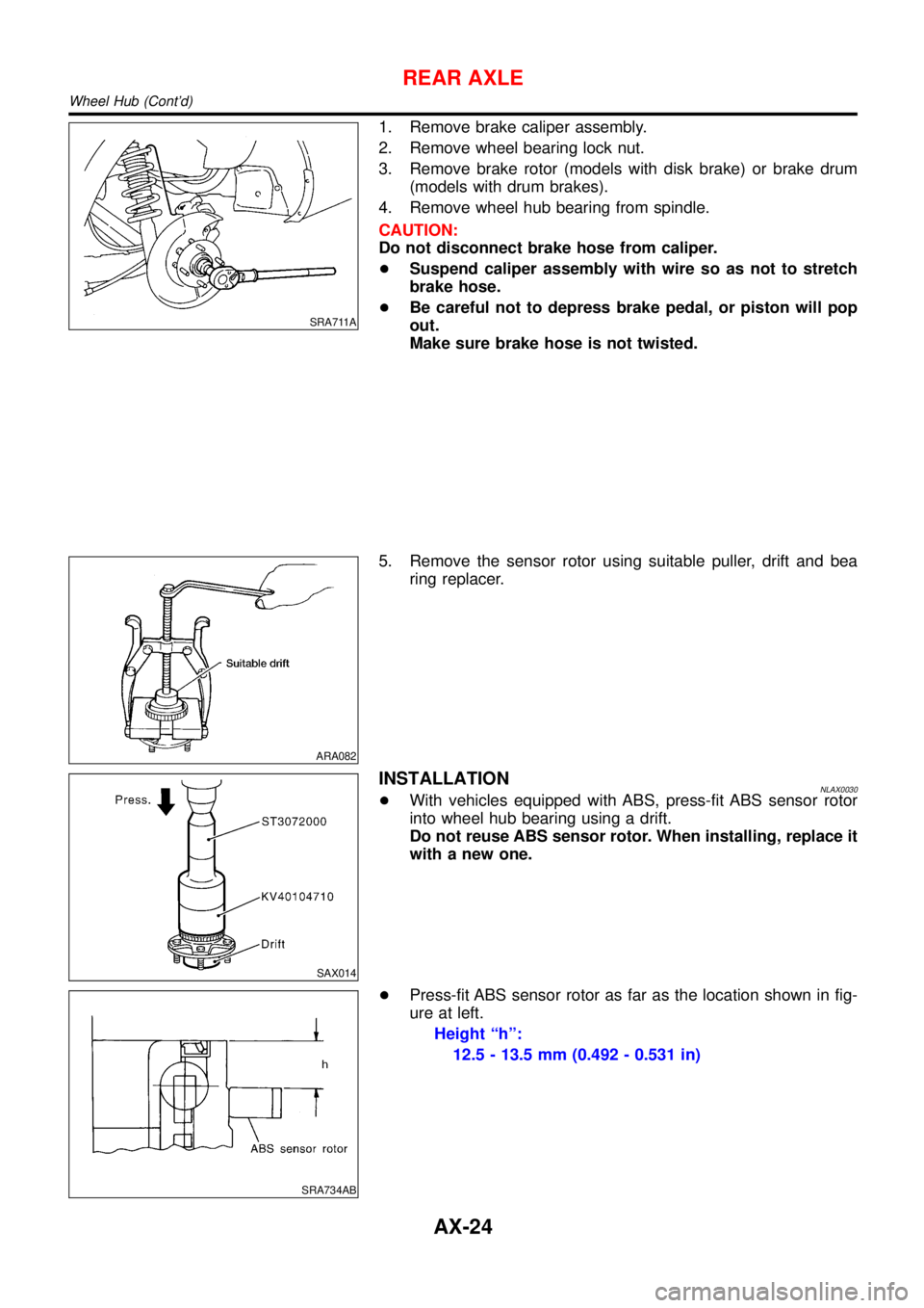
SRA711A
1. Remove brake caliper assembly.
2. Remove wheel bearing lock nut.
3. Remove brake rotor (models with disk brake) or brake drum
(models with drum brakes).
4. Remove wheel hub bearing from spindle.
CAUTION:
Do not disconnect brake hose from caliper.
+Suspend caliper assembly with wire so as not to stretch
brake hose.
+Be careful not to depress brake pedal, or piston will pop
out.
Make sure brake hose is not twisted.
ARA082
5. Remove the sensor rotor using suitable puller, drift and bea
ring replacer.
SAX014
INSTALLATIONNLAX0030+With vehicles equipped with ABS, press-fit ABS sensor rotor
into wheel hub bearing using a drift.
Do not reuse ABS sensor rotor. When installing, replace it
with a new one.
SRA734AB
+Press-fit ABS sensor rotor as far as the location shown in fig-
ure at left.
Height“h”:
12.5 - 13.5 mm (0.492 - 0.531 in)
REAR AXLE
Wheel Hub (Cont’d)
AX-24
Page 238 of 3051
BRAKE SYSTEM
SECTION
BR
CONTENTS
PRECAUTIONS...............................................................3
Supplemental Restraint System (SRS)″AIR
BAG″and″SEAT BELT PRE-TENSIONER″...............3
Precautions for Brake System .....................................3
Precautions When Working On ABS ...........................4
Wiring Diagrams and Trouble Diagnosis .....................4
PREPARATION...............................................................5
Commercial Service Tools ...........................................5
NOISE, VIBRATION AND HARSHNESS (NVH)
TROUBLESHOOTING.....................................................6
NVH Troubleshooting Chart.........................................6
ON-VEHICLE SERVICE..................................................7
Checking Brake Fluid Level.........................................7
Checking Brake Line ...................................................7
Changing Brake Fluid ..................................................7
Brake Burnishing Procedure........................................7
Bleeding Brake System ...............................................8
BRAKE HYDRAULIC LINE.............................................9
Hydraulic Circuit...........................................................9
Removal .......................................................................9
Inspection.....................................................................9
Installation ..................................................................10
BRAKE PEDAL AND BRACKET.................................. 11
Removal and Installation ........................................... 11
Inspection................................................................... 11
Adjustment ................................................................. 11
MASTER CYLINDER.....................................................13
Removal .....................................................................13
Disassembly...............................................................13
Inspection...................................................................14
Assembly ...................................................................14
Installation ..................................................................15
BRAKE BOOSTER........................................................16
On-vehicle Service.....................................................16
OPERATING CHECK...............................................16
AIRTIGHT CHECK...................................................16
Removal .....................................................................16
Inspection...................................................................16
OUTPUT ROD LENGTH CHECK..............................16Installation ..................................................................17
VACUUM HOSE.............................................................18
Removal and Installation ...........................................18
Inspection...................................................................19
HOSES AND CONNECTORS...................................19
CHECK VALVE........................................................19
VACUUM PUMP............................................................20
Removal .....................................................................20
Installation ..................................................................21
Inspection...................................................................21
Component ................................................................22
Disassembly...............................................................22
Assembly ...................................................................22
FRONT DISC BRAKE...................................................24
Component ................................................................24
Pad Replacement ......................................................24
Removal .....................................................................25
Disassembly...............................................................25
Inspection...................................................................25
CALIPER.................................................................25
ROTOR...................................................................26
Assembly ...................................................................27
Installation ..................................................................27
REAR DISC BRAKE (CAM & STRUT TYPE)..............28
Component ................................................................28
Pad Replacement ......................................................28
Removal .....................................................................30
Disassembly...............................................................30
Inspection...................................................................31
CALIPER.................................................................31
ROTOR...................................................................32
Assembly ...................................................................32
Installation ..................................................................35
REAR DISC BRAKE (BALL & RAMP TYPE)..............36
Component ................................................................36
Pad Replacement ......................................................36
Removal .....................................................................38
Disassembly...............................................................38
Inspection...................................................................38
Page 239 of 3051
CALIPER.................................................................38
ROTOR...................................................................39
Installation ..................................................................39
PARKING BRAKE CONTROL......................................40
Components...............................................................40
Removal and Installation ...........................................40
Inspection...................................................................40
Adjustment .................................................................41
ABS
DESCRIPTION...............................................................42
Purpose......................................................................42
ABS (Anti-Lock Brake System) Operation ................42
ABS Hydraulic Circuit ................................................42
System Components .................................................43
System Description ....................................................43
SENSOR.................................................................43
CONTROL UNIT......................................................43
ABS ACTUATOR AND ELECTRIC UNIT....................43
Component Parts and Harness Connector
Location .....................................................................45
Schematic ..................................................................46
MODELS WITH SELF-DIAGNOSIS FUNCTION
(DATA LINK CONNECTOR TERMINAL NO. 9)
...........46
MODELS WITHOUT SELF-DIAGNOSIS
FUNCTION (DATA LINK CONNECTOR TERMINAL
NO. 9)
.....................................................................47
Wiring Diagram - ABS - .............................................48
MODELS WITH SELF-DIAGNOSIS FUNCTION
(DATA LINK CONNECTOR TERMINAL NO. 9)
...........48
MODELS WITHOUT SELF-DIAGNOSIS
FUNCTION (DATA LINK CONNECTOR TERMINAL
NO. 9)
.....................................................................52
ON BOARD DIAGNOSTIC SYSTEM
DESCRIPTION...............................................................56
Self-diagnosis (Only models with data link
connector terminal No. 9) ..........................................56
FUNCTION..............................................................56
SELF-DIAGNOSIS PROCEDURE..............................56
HOW TO READ SELF-DIAGNOSTIC RESULTS
(MALFUNCTION CODES)
........................................57
HOW TO ERASE SELF-DIAGNOSTIC RESULTS
(MALFUNCTION CODES)
........................................57
CONSULT-II ...............................................................58
CONSULT-II APPLICATION TO ABS..........................58
ECU (ABS CONTROL UNIT) PART NUMBER
MODE
.....................................................................58
CONSULT-II Inspection Procedure............................58
SELF-DIAGNOSIS PROCEDURE..............................58
SELF-DIAGNOSTIC RESULTS MODE.......................60
DATA MONITOR PROCEDURE................................61
ACTIVE TEST PROCEDURE....................................62
DATA MONITOR MODE...........................................63
ACTIVE TEST MODE...............................................63
TROUBLE DIAGNOSIS - INTRODUCTION..................64
How to Perform Trouble Diagnoses for Quick
and Accurate Repair ..................................................64
INTRODUCTION......................................................64
TROUBLE DIAGNOSIS - BASIC INSPECTION...........65
Preliminary Check......................................................65
Ground Circuit Check ................................................68
ABS ACTUATOR AND ELECTRIC UNIT GROUND.....68
TROUBLE DIAGNOSIS - GENERAL
DESCRIPTION...............................................................69
Malfunction Code/Symptom Chart.............................69
MODELS WITH SELF-DIAGNOSIS FUNCTION
(DATA LINK CONNECTOR TERMINAL NO. 9)
...........69
TROUBLE DIAGNOSES FOR SELF-DIAGNOSTIC
ITEMS.............................................................................71
Wheel Sensor or Rotor ..............................................71
DIAGNOSTIC PROCEDURE.....................................71
ABS Actuator Solenoid Valve or Solenoid Valve
Relay ..........................................................................74
DIAGNOSTIC PROCEDURE.....................................74
Motor Relay or Motor.................................................77
DIAGNOSTIC PROCEDURE.....................................77
Low Voltage ...............................................................79
DIAGNOSTIC PROCEDURE.....................................79
Control Unit ................................................................81
DIAGNOSTIC PROCEDURE.....................................81
TROUBLE DIAGNOSES FOR SYMPTOMS.................82
1. ABS Works Frequently ..........................................82
2. Unexpected Pedal Action ......................................82
3. Long Stopping Distance ........................................83
4. ABS Does Not Work ..............................................84
5. Pedal Vibration and Noise.....................................85
6. ABS Warning Lamp Does Not Come On
When Ignition Switch Is Turned On...........................86
7. ABS Warning Lamp Stays On When Ignition
Switch Is Turned On ..................................................88
REMOVAL AND INSTALLATION.................................90
Wheel Sensors ..........................................................90
ABS Actuator and Electric Unit..................................91
REMOVAL...............................................................91
INSTALLATION........................................................91
Sensor Rotor..............................................................92
REMOVAL...............................................................92
INSTALLATION........................................................92
SERVICE DATA AND SPECIFICATIONS (SDS).........93
General Specifications ...............................................93
Disc Brake .................................................................93
Brake Pedal ...............................................................93
Parking Brake ............................................................93
CONTENTS(Cont’d)
BR-2
Page 240 of 3051
Supplemental Restraint System (SRS)“AIR
BAG”and“SEAT BELT PRE-TENSIONER”
NLBR0081The Supplemental Restraint System such as “AIR BAG” and “SEAT BELT PRE-TENSIONER” used along with
a seat belt, helps to reduce the risk or severity of injury to the driver and front passenger for certain types of
collision. The SRS system composition which is available to NISSAN MODEL V10 is as follows (The compo-
sition varies according to the destination and optional equipment.):
+For a frontal collision
The Supplemental Restraint System consists of driver air bag module (located in the center of the steer-
ing wheel), front passenger air bag module (located on the instrument panel on passenger side), front seat
belt pre-tensioners, a diagnosis sensor unit, warning lamp, wiring harness and spiral cable.
+For a side collision
The Supplemental Restraint System consists of front side air bag module (located in the outer side of front
seat), side air bag (satellite) sensor, diagnosis sensor unit (one of components of air bags for a frontal
collision), wiring harness, warning lamp (one of components of air bags for a frontal collision).
Information necessary to service the system safely is included in theRS sectionof this Service Manual.
WARNING:
+To avoid rendering the SRS inoperative, which could increase the risk of personal injury or death
in the event of a collision which would result in air bag inflation, all maintenance should be per-
formed by an authorized NISSAN dealer.
+Improper maintenance, including incorrect removal and installation of the SRS, can lead to per-
sonal injury caused by unintentional activation of the system. For removal of Spiral Cable and Air
Bag Module, see the RS section.
+Do not use electrical test equipment on any circuit related to the SRS unless instructed to in this
Service Manual. Spiral cable and wiring harnesses covered with yellow insulation tape either just
before the harness connectors or for the complete harness are related to the SRS.
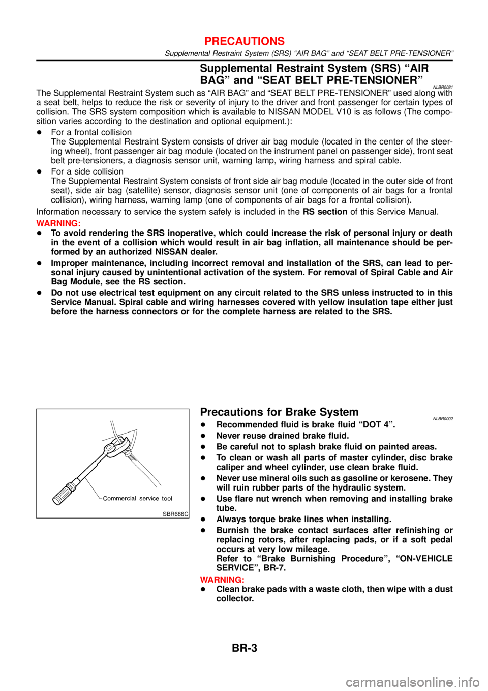
SBR686C
Precautions for Brake SystemNLBR0002+Recommended fluid is brake fluid“DOT 4”.
+Never reuse drained brake fluid.
+Be careful not to splash brake fluid on painted areas.
+To clean or wash all parts of master cylinder, disc brake
caliper and wheel cylinder, use clean brake fluid.
+Never use mineral oils such as gasoline or kerosene. They
will ruin rubber parts of the hydraulic system.
+Use flare nut wrench when removing and installing brake
tube.
+Always torque brake lines when installing.
+Burnish the brake contact surfaces after refinishing or
replacing rotors, after replacing pads, or if a soft pedal
occurs at very low mileage.
Refer to“Brake Burnishing Procedure”,“ON-VEHICLE
SERVICE”, BR-7.
WARNING:
+Clean brake pads with a waste cloth, then wipe with a dust
collector.
PRECAUTIONS
Supplemental Restraint System (SRS) “AIR BAG” and “SEAT BELT PRE-TENSIONER”
BR-3
Page 243 of 3051

NLBR0005
NVH Troubleshooting ChartNLBR0005S01Use the table below to help you find the cause of the symptom. If necessary, repair or replace these parts.
Reference page
BR-24, 28
BR-24, 28
BR-24, 28
—
—
BR-26, 32
—
—
—
BR-26, 32
NVH in FA section
NVH in FA section
NVH in FA, RA section
NVH in FA section
NVH in ST section
SUSPECTED PARTS
(Possible cause)
Pads - damaged
Pads - uneven wear
Shims damaged
Rotor imbalance
Rotor damage
Rotor runout
Rotor deformation
Rotor deflection
Rotor rust
Rotor thickness variation
DRIVE SHAFT
AXLE AND SUSPENSION
TIRES
ROAD WHEEL
STEERING
Symptom BRAKENoise X X XXXXXX
Shake XXXXXX
Shimmy, Jud-
derXXXXXXX XXXX
X: Applicable
NOISE, VIBRATION AND HARSHNESS (NVH) TROUBLESHOOTING
NVH Troubleshooting Chart
BR-6
Page 244 of 3051

NBR376
Checking Brake Fluid LevelNLBR0006+Check fluid level in reservoir tank. It should be between Max
and Min lines on reservoir tank.
+If fluid level is extremely low, check brake system for leaks.
+Release parking brake lever and see if brake warning lamp
goes off. If not, check brake system for leaks.
SBR389C
Checking Brake LineNLBR0007CAUTION:
If leakage occurs around joints, retighten or, if necessary,
replace damaged parts.
1. Check brake lines (tubes and hoses) for cracks, deterioration
or other damage. Replace any damaged parts.
2. Check for oil leakage by fully depressing brake pedal while
engine is running.
SBR419C
Changing Brake FluidNLBR0008CAUTION:
+Refill with new brake fluid“DOT 4”.
+Always keep fluid level higher than minimum line on res-
ervoir tank.
+Never reuse drained brake fluid.
+Be careful not to splash brake fluid on painted areas; it
may cause paint damage. If brake fluid is splashed on
painted areas, wash it away with water immediately.
1. Clean inside of reservoir tank, and refill with new brake fluid.
2. Connect a vinyl tube to each air bleeder valve.
3. Drain brake fluid from each air bleeder valve by depressing
brake pedal while keeping reservoir level higher than minimum
line by adding new brake fluid.
4. Repeat until new brake fluid comes out of each air bleeder
valve.
Use same procedure as in bleeding hydraulic system to refill
brake fluid. Refer to“Bleeding Brake System”, BR-8 and“Air
Bleeding Procedure”, CL-10.
Brake Burnishing ProcedureNLBR0036Burnish the brake contact surfaces according to the following pro-
cedure after refinishing or replacing rotors, after replacing pads, or
if a soft pedal occurs at very low mileage.
CAUTION:
Only perform this procedure under safe road and traffic con-
ditions. Use extreme caution.
1. Drive the vehicle on a straight smooth road at 50 km/h (31
MPH).
2. Use medium brake pedal/foot effort to bring the vehicle to a
complete stop from 50 km/h (31 MPH). Adjust brake pedal/foot
ON-VEHICLE SERVICE
Checking Brake Fluid Level
BR-7
Page 261 of 3051
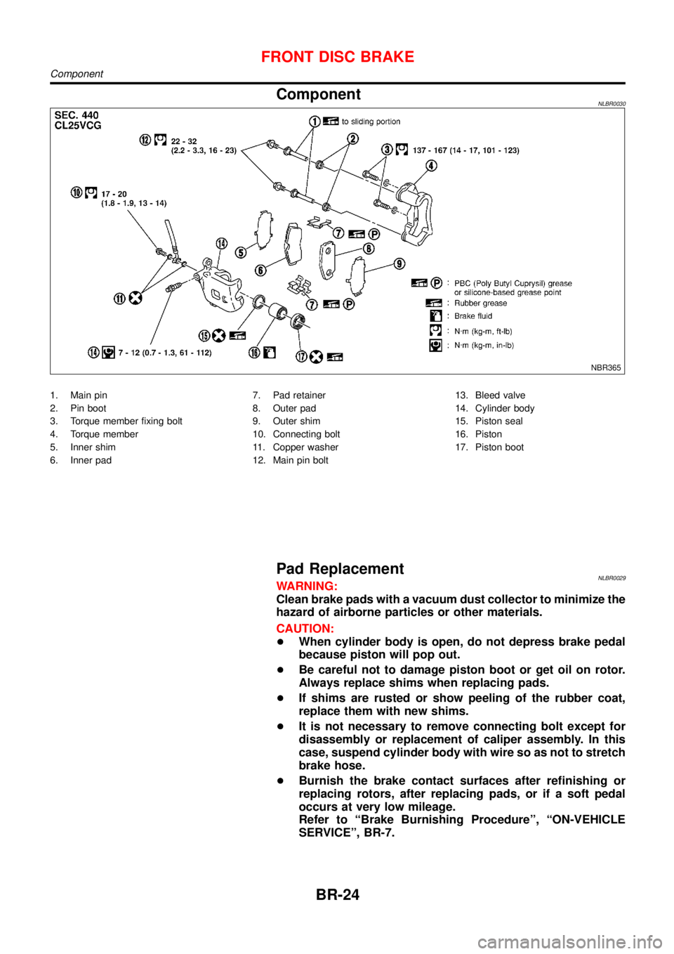
ComponentNLBR0030
NBR365
1. Main pin
2. Pin boot
3. Torque member fixing bolt
4. Torque member
5. Inner shim
6. Inner pad7. Pad retainer
8. Outer pad
9. Outer shim
10. Connecting bolt
11. Copper washer
12. Main pin bolt13. Bleed valve
14. Cylinder body
15. Piston seal
16. Piston
17. Piston boot
Pad ReplacementNLBR0029WARNING:
Clean brake pads with a vacuum dust collector to minimize the
hazard of airborne particles or other materials.
CAUTION:
+When cylinder body is open, do not depress brake pedal
because piston will pop out.
+Be careful not to damage piston boot or get oil on rotor.
Always replace shims when replacing pads.
+If shims are rusted or show peeling of the rubber coat,
replace them with new shims.
+It is not necessary to remove connecting bolt except for
disassembly or replacement of caliper assembly. In this
case, suspend cylinder body with wire so as not to stretch
brake hose.
+Burnish the brake contact surfaces after refinishing or
replacing rotors, after replacing pads, or if a soft pedal
occurs at very low mileage.
Refer to“Brake Burnishing Procedure”,“ON-VEHICLE
SERVICE”, BR-7.
FRONT DISC BRAKE
Component
BR-24
Page 263 of 3051
PistonNLBR0033S0102CAUTION:
Piston sliding surface is plated. Do not polish with emery
paper even if rust or foreign materials are stuck to sliding
surface.
Check piston for score, rust, wear, damage or presence of foreign
materials. Replace if any of the above conditions are observed.
Slide Pin, Pin Bolt and Pin BootNLBR0033S0103Check for wear, cracks or other damage. Replace if any of the
above conditions are observed.
ROTORNLBR0033S02Rubbing SurfaceNLBR0033S0201Check rotor for roughness, cracks or chips.
SBR219C
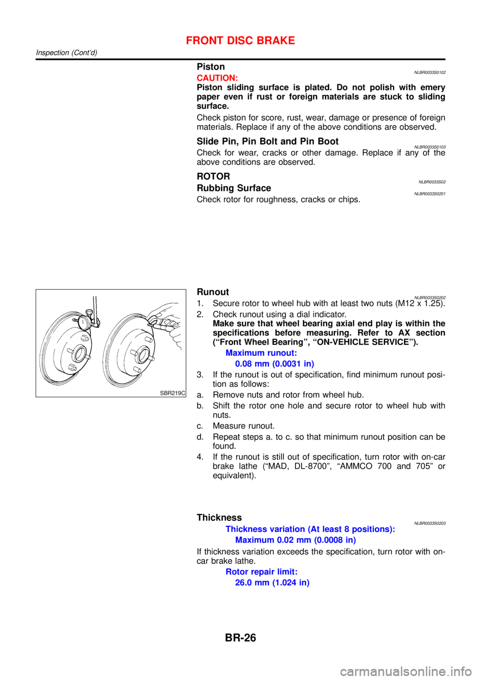
RunoutNLBR0033S02021. Secure rotor to wheel hub with at least two nuts (M12 x 1.25).
2. Check runout using a dial indicator.
Make sure that wheel bearing axial end play is within the
specifications before measuring. Refer to AX section
(“Front Wheel Bearing”,“ON-VEHICLE SERVICE”).
Maximum runout:
0.08 mm (0.0031 in)
3. If the runout is out of specification, find minimum runout posi-
tion as follows:
a. Remove nuts and rotor from wheel hub.
b. Shift the rotor one hole and secure rotor to wheel hub with
nuts.
c. Measure runout.
d. Repeat steps a. to c. so that minimum runout position can be
found.
4. If the runout is still out of specification, turn rotor with on-car
brake lathe (“MAD, DL-8700”,“AMMCO 700 and 705”or
equivalent).
ThicknessNLBR0033S0203Thickness variation (At least 8 positions):
Maximum 0.02 mm (0.0008 in)
If thickness variation exceeds the specification, turn rotor with on-
car brake lathe.
Rotor repair limit:
26.0 mm (1.024 in)
FRONT DISC BRAKE
Inspection (Cont’d)
BR-26