CHAIN NISSAN ALMERA TINO 2001 Service Owner's Guide
[x] Cancel search | Manufacturer: NISSAN, Model Year: 2001, Model line: ALMERA TINO, Model: NISSAN ALMERA TINO 2001Pages: 3051, PDF Size: 46.38 MB
Page 2285 of 3051

SEM519G
6. Install camshaft sprocket bolts and tighten them to correct
torque.
+Apply new engine oil to bolt threads and seat surface.
SEM520G
7. Install chain tensioner.
+Before installing chain tensioner, insert a suitable pin into
pin hole of chain tensioner.
+After installing chain tensioner, remove the pin.
8. Install timing chain guide.
SEM893F
9. Install O-rings to cylinder block.
SEM894F
10. Before installing front cover, remove all traces of liquid gasket
from mating surface using a scraper.
+Also remove traces of liquid gasket from mating surface of
cylinder block.
SEM895F
11. Apply a continuous bead of liquid gasket to mating surface of
front cover.
+Check alignment of mating marks on chain and crankshaft
sprocket.
+Align oil drive spacer with oil pump.
+Place timing chain to the side of chain guide. This pre-
vents the chain from making contact with water seal area
of front cover.
TIMING CHAINQG
Installation (Cont'd)
EM-28
Page 2286 of 3051

SEM896F
12. Install front cover.
Bolt No. Tightening torque N´m (kg-m, in-lb) ª!º mm (in)
a. 6.9 - 9.5 (0.70 - 0.97, 61 - 84) 20 (0.79)
b. 6.9 - 9.5 (0.70 - 0.97, 61 - 84) 40 (1.57)
c. 17 - 24 (1.7 - 2.4, 148 - 208*) 70 (2.76)
d. 6.9 - 9.5 (0.70 - 0.97, 61 - 84) 72.8 (2.866)
e. 6.9 - 9.5 (0.70 - 0.97, 61 - 84) 12 (0.47)
*: 12 - 17 ft-lb
SEM897F
+Make sure two O-rings are present.
+Be careful not to damage oil seal when installing front
cover.
SEM009G
13. Install cylinder head bolts at engine front side.
+Tightening procedure
Tightening bolts (1 - 4) to 6.3 to 8.3 N´m (0.64 to 0.85 kg-m,
55.8 to 73.5 in-lb).
SEM945F
14. Install oil pump drive spacer.
SEM104G
15. Install water pump and water pump pulley.
Refer to LC-14, ªWater Pumpº.
16. Install idler pulley and bracket.
17. Install RH engine mounting bracket.
18. Install RH engine mounting.
19. Install oil strainer.
20. Install oil pan. Refer to EM-21, ªInstallationº.
21. Install crankshaft pulley.
22. Remove ring gear stopper.
23. Install starter motor.
TIMING CHAINQG
Installation (Cont'd)
EM-29
Page 2287 of 3051

SEM887F
24. Install cylinder head front cover.
+Apply liquid gasket to cylinder head front cover.
+Use Genuine Liquid Gasket or equivalent.
SEM889F
25. Install camshaft position sensor (PHASE).
SEM888F
26. Before installing rocker cover, apply a continuous bead of liq-
uid gasket to mating surface of cylinder head.
SEM105G
27. Install rocker cover with rocker cover gasket and tighten bolts
in numerical order as shown in the figure.
28. Install spark plugs.
29. Install ignition coils.
30. Install front exhaust tube.
31. Install front/right splash undercover.
32. Install front right-side wheel.
33. Drive belts.
For adjusting drive belt deflection, refer to EM-17, ªCheckingº.
34. Reinstall parts in reverse order of removal.
TIMING CHAINQG
Installation (Cont'd)
EM-30
Page 2290 of 3051

ComponentsNLEM0108
SEM106G
1. Oil filler cap
2. Rocker cover
3. Rocker cover gasket
4. Intake valve timing control sole-
noid (Models with intake valve tim-
ing control)
5. Camshaft bracket
6. Intake camshaft7. Exhaust camshaft
8. Timing chain guide
9. Cylinder head bolt
10. Shim
11. Valve lifter
12. Valve cotter
13. Valve spring retainer
14. Valve spring15. Valve spring seat
16. Valve oil seal
17. Valve guide
18. Cylinder head
19. Cylinder head gasket
20. Valve seat
21. Valve
CYLINDER HEADQG
Components
EM-33
Page 2292 of 3051

SEM873F
+Rotate crankshaft until mating mark on camshaft sprocket
is set at position indicated in figure at left.
SEM874F
14. Remove camshaft position sensor (PHASE).
+Do not allow any magnetic materials to contact the cam-
shaft position sensor (PHASE).
+Be careful not to damage sensor.
15. Remove cylinder head front cover.
SEM875F
16. Remove timing chain guide from camshaft bracket.
17. Attach a suitable stopper pin to chain tensioner.
18. Remove chain tensioner.
SEM876F
19. Remove camshaft sprocket bolts.
+Apply paint to timing chain and cam sprockets for align-
ment during installation.
20. Remove camshaft sprockets.
SEM877F
21. Remove camshaft brackets and camshafts.
+Apply I.D. marks to brackets to ensure correct reassembly.
+Bolts should be loosened in two or three steps.
CYLINDER HEADQG
Removal (Cont'd)
EM-35
Page 2304 of 3051

SEM904F
+Apply new engine oil to bolt threads and seat surface.
+Tighten camshaft bracket bolts in the following steps.
a. Tighten bolts9-12,then1-8.
2.0 N´m (0.204 kg-m, 17.7 in-lb)
b. Tighten bolts1-12.
5.9 N´m (0.60 kg-m, 52.2 in-lb)
c. Tighten bolts1-12.
9.0 - 11.8 N´m (0.92 - 1.20 kg-m, 80 - 104 in-lb)
+If any part of valve assembly or camshaft is replaced,
check valve clearance according to reference data.
After completing assembly check valve clearance. Refer
to ªCheckingº and ªAdjustingº in ªVALVE CLEARANCEº
(EM-42).
Reference data valve clearance (Cold):
Intake
0.25 - 0.33 mm (0.010 - 0.013 in)
Exhaust
0.32 - 0.40 mm (0.013 - 0.016 in)
SEM905F
6. Install camshaft sprocket.
+Set timing chain by aligning mating marks with those of
camshaft sprockets.
SEM906F
7. Install camshaft sprocket bolts to correct torque.
+Apply new engine oil to bolt threads and seat surface.
SEM907F
8. Install chain tensioner.
+Before installing chain tensioner, insert a suitable pin into
pin hole of chain tensioner.
+After installing chain tensioner, remove the pin.
9. Install timing chain guide.
CYLINDER HEADQG
Installation (Cont'd)
EM-47
Page 2310 of 3051
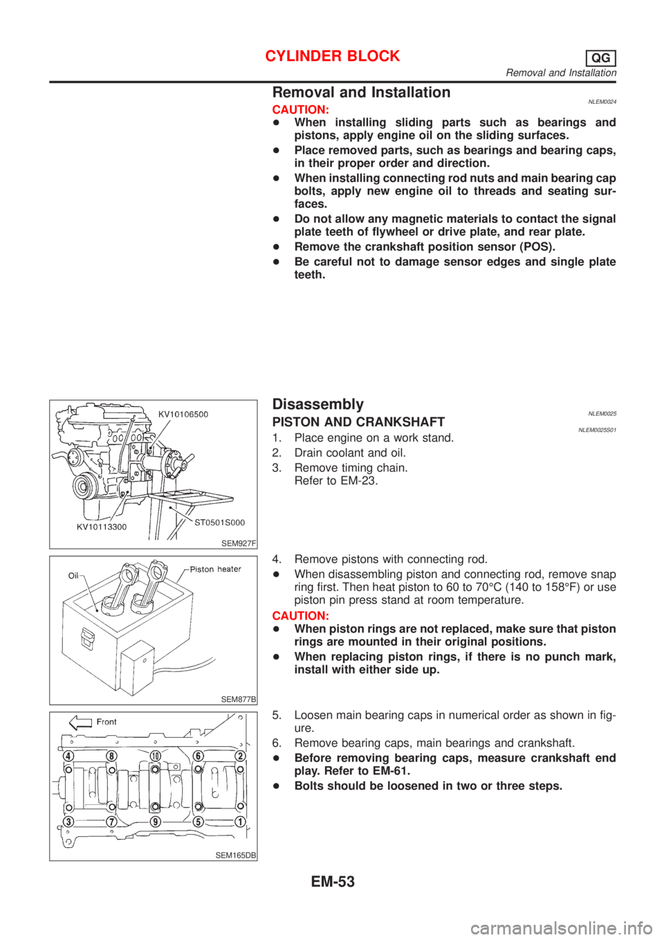
Removal and InstallationNLEM0024CAUTION:
+When installing sliding parts such as bearings and
pistons, apply engine oil on the sliding surfaces.
+Place removed parts, such as bearings and bearing caps,
in their proper order and direction.
+When installing connecting rod nuts and main bearing cap
bolts, apply new engine oil to threads and seating sur-
faces.
+Do not allow any magnetic materials to contact the signal
plate teeth of flywheel or drive plate, and rear plate.
+Remove the crankshaft position sensor (POS).
+Be careful not to damage sensor edges and single plate
teeth.
SEM927F
DisassemblyNLEM0025PISTON AND CRANKSHAFTNLEM0025S011. Place engine on a work stand.
2. Drain coolant and oil.
3. Remove timing chain.
Refer to EM-23.
SEM877B
4. Remove pistons with connecting rod.
+When disassembling piston and connecting rod, remove snap
ring first. Then heat piston to 60 to 70ÉC (140 to 158ÉF) or use
piston pin press stand at room temperature.
CAUTION:
+When piston rings are not replaced, make sure that piston
rings are mounted in their original positions.
+When replacing piston rings, if there is no punch mark,
install with either side up.
SEM165DB
5. Loosen main bearing caps in numerical order as shown in fig-
ure.
6. Remove bearing caps, main bearings and crankshaft.
+Before removing bearing caps, measure crankshaft end
play. Refer to EM-61.
+Bolts should be loosened in two or three steps.
CYLINDER BLOCKQG
Removal and Installation
EM-53
Page 2338 of 3051

Use the table below to help you find the cause of the symptom.
1. Locate the area where noise occurs.
2. Confirm the type of noise.
3. Specify the operating condition of the engine.
4. Check the specified noise source.
If necessary, repair or replace these parts.
NVH Troubleshooting Ð Engine NoiseNLEM0116S01
Location of
noiseType of
noiseOperating condition of engine
Source of
noiseCheck itemReference
page Before
warm-
upAfter
warm-
upWhen
start-
ingWhen
idlingWhen
racingWhile
driving
To p o f
engine
Rocket
cover
Cylinder
headTicking or
clickingC A Ð A B Ð Rocker
noiseHydraulic lash adjuster EM-119
Rattle C A Ð A B C Camshaft
bearing
noiseCamshaft journal clear-
ance
Camshaft runoutEM-115
Crankshaft
pulley
Cylinder
block (Side
of engine)
Oil panSlap or
knockÐ A Ð B B Ð Piston pin
noisePiston and piston pin
clearance
Connecting rod bushing
clearanceEM-134,
141
Slap or
rapA Ð Ð B B A Piston slap
noisePiston-to-bore clearance
Piston ring side clearance
Piston ring end gap
Connecting rod bend and
torsionEM-135,
136,
137
Knock A B CB B B Connecting
rod bearing
noiseConnecting rod bushing
clearance (Small end)
Connecting rod bearing
clearance (Big end)EM-140,
141
Knock A B Ð A B C Main bear-
ing noiseMain bearing oil clear-
ance
Crankshaft runoutEM-138
Front of
engine
Timing
chain coverTapping
or tickingAAÐBBBTiming
chain and
chain ten-
sioner noiseTiming chain cracks and
wear
Timing chain tensioner
operationEM-100
Front of
engineSqueak or
fizzingA B Ð B Ð C Other drive
belts (Stick-
ing or slip-
ping)Drive belts deflection EM-86,
ªChecking
Drive Beltsº
CreakingABABABOther drive
belts (Slip-
ping)Idler pulley bearing
operation
Squall
CreakABÐBABWater
pump noiseWater pump operation LC-34,
ªWater
Pump
Inspectionº
A: Closely related B: Related C: Sometimes related Ð: Not related
NOISE, VIBRATION AND HARSHNESS (NVH) TROUBLESHOOTINGSR
Commercial Service Tools (Cont'd)
EM-81
Page 2353 of 3051

ComponentsNLEM0125
YEM007
1. Cylinder block
2. Upper chain guide
3. Intake camshaft sprocket
4. Chain tensioner5. Chain guide
6. Front cover
7. Crank pulley
8. Oil pump spacer9. Crankshaft sprocket
10. Chain guide
11. Timing chain
12. Exhaust camshaft sprocket
TIMING CHAINSR
Components
EM-96
Page 2354 of 3051

CAUTION:
+After removing timing chain, do not turn crankshaft and
camshaft separately, or valves will strike piston heads.
+When installing chain tensioner, oil seals, or other sliding
parts, lubricate contacting surfaces with new engine oil.
+Apply new engine oil to bolt threads and seat surfaces
when installing camshaft sprocket and crankshaft pulley.
RemovalNLEM01261. Remove engine under cover.
2. Remove front RH wheel and engine side cover.
3. Drain coolant by removing cylinder block drain plug and lower
radiator hose. Refer to LC-38, ªChanging Engine Coolantº.
4. Remove drive belts and water pump pulley.
5. Disconnect the following parts:
+Vacuum hoses
+Wires
+Harness
+Connectors
SEM029G
6. Remove rocker cover bolts in numerical order.
7. Remove rocker cover.
SEM287G
8. Remove cylinder head outside bolts.
TIMING CHAINSR
Components (Cont'd)
EM-97