check oil NISSAN ALMERA TINO 2001 Service Service Manual
[x] Cancel search | Manufacturer: NISSAN, Model Year: 2001, Model line: ALMERA TINO, Model: NISSAN ALMERA TINO 2001Pages: 3051, PDF Size: 46.38 MB
Page 1004 of 3051

4. Remove ventilation hose.
5. Disconnect injector harness connectors.
6. Disconnect fuel pressure regulator vacuum hose from intake
manifold collector.
7. Disconnect fuel hoses from fuel tube assembly.
8. Remove injectors with fuel tube assembly.
SEF703X
9. Expand and remove clips securing fuel injectors.
10. Extract fuel injectors straight from fuel tubes.
+Be careful not to damage injector nozzles during removal.
+Do not bump or drop fuel injectors.
11. Carefully install O-rings, including the one used with the pres-
sure regulator.
+Lubricate O-rings with a smear of engine oil.
+Be careful not to damage O-rings with service tools or
finger nails or clips. Do not expand or twist O-rings.
+Discard old clips; replace with new ones.
12. Position clips in grooves on fuel injectors.
+Make sure that protrusions of fuel injectors are aligned
with cutouts of clips after installation.
13. Align protrusions of fuel tubes with those of fuel injectors.
14. After properly inserting fuel injectors, check to make sure that
fuel tube protrusions are engaged with those of fuel injectors,
and that flanges of fuel tubes are engaged with clips.
SEF828X
15. Tighten fuel tube assembly mounting nuts in two stages.
: Tightening torque N´m (kg-m, ft-lb)
1st stage:
9.4 - 10.7 (0.95 - 1.1, 6.9 - 7.9)
2nd stage:
21 - 26 (2.1 - 2.7, 16 - 19)
16. Install all removed parts in the reverse order of removal.
CAUTION:
After properly connecting fuel tube assembly to injector and
fuel hose, check connection for fuel leakage.
SEF910X
THROTTLE OPENER (WHERE FITTED)NLEC1747InspectionNLEC1747S011. Start engine and let it idle.
2. Confirm the amount of the rod moves ªLº more than 3.0 mm
(0.118 in), the throttle drum becomes free from the rod of the
throttle opener.
If NG, go to next step.
If OK, inspection is complete.
BASIC SERVICE PROCEDURESR20DE
Injector (Cont'd)
EC-579
Page 1039 of 3051

Monitored item [Unit]ECM
input
signalsMain
signalsDescription Remarks
A/F ALPHA-B1 [%]j+Indicates the mean value of the air-fuel ratio
feedback correction factor per cycle.+When the engine is running, specifi-
cation range is indicated.
+This data also includes the data for
the air-fuel ratio learning control.
NOTE:
Any monitored item that does not match the vehicle being diagnosed is deleted from the display automatically.
ACTIVE TEST MODENLEC1365S08
TEST ITEM CONDITION JUDGEMENT CHECK ITEM (REMEDY)
FUEL INJEC-
TION+Engine: Return to the original
trouble condition
+Change the amount of fuel injec-
tion using CONSULT-II.If trouble symptom disappears, see
CHECK ITEM.+Harness and connector
+Fuel injectors
+Heated oxygen sensor 1 (front)
IGNITION TIM-
ING+Engine: Return to the original
trouble condition
+Timing light: Set
+Retard the ignition timing using
CONSULT-II.If trouble symptom disappears, see
CHECK ITEM.+Adjust initial ignition timing.
IACV-AAC/V
OPENING+Engine: After warming up, idle
the engine.
+Change the IACV-AAC valve
opening steps using CONSULT-
II.Engine speed changes according
to the opening steps.+Harness and connector
+IACV-AAC valve
POWER BAL-
ANCE+Engine: After warming up, idle
the engine.
+Air conditioner switch ªOFFº
+Shift lever ªNº
+Cut off each injector signal one
at a time using CONSULT-II.Engine runs rough or dies.+Harness and connector
+Compression
+Injectors
+Power transistor
+Spark plugs
+Ignition coil
+Ignition wires
COOLING FAN+Ignition switch: ON
+Turn the cooling fan ªHIGHº,
ªLOWº and ªOFFº using CON-
SULT-II.Cooling fan moves at high speed or
low speed and stops.+Harness and connector
+Cooling fan motors
+Cooling fan relays
ENG COOLANT
TEMP+Engine: Return to the original
trouble condition
+Change the engine coolant tem-
perature indication using CON-
SULT-II.If trouble symptom disappears, see
CHECK ITEM.+Harness and connector
+Engine coolant temperature sen-
sor
+Fuel injectors
FUEL PUMP
RELAY+Ignition switch: ON
(Engine stopped)
+Turn the fuel pump relay ªONº
and ªOFFº using CONSULT-II
and listen to operating sound.Fuel pump relay makes the operat-
ing sound.+Harness and connector
+Fuel pump relay
EGR VOL
CONT/V
(where fitted)+Engine: After warming up, idle
the engine.
+Change the EGR volume control
valve opening step using CON-
SULT-II.EGR volume control valve maks an
operating sound.+Harness and connector
+EGR volume control valve
ON BOARD DIAGNOSTIC SYSTEM DESCRIPTIONSR20DE
CONSULT-II (Cont'd)
EC-614
Page 1236 of 3051
6 CHECK IGNITION SIGNAL CIRCUIT
Refer to ªDiagnostic Procedureº, EC-1008.
OK or NG
OK©GO TO 7.
NG©Repair or replace malfunctioning parts.
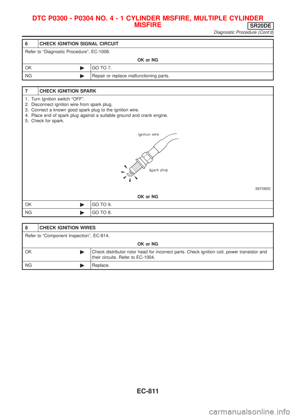
7 CHECK IGNITION SPARK
1. Turn Ignition switch ªOFFº.
2. Disconnect ignition wire from spark plug.
3. Connect a known good spark plug to the ignition wire.
4. Place end of spark plug against a suitable ground and crank engine.
5. Check for spark.
SEF282G
OK or NG
OK©GO TO 9.
NG©GO TO 8.
8 CHECK IGNITION WIRES
Refer to ªComponent Inspectionº, EC-814.
OK or NG
OK©Check distributor rotor head for incorrect parts. Check ignition coil, power transistor and
their circuits. Refer to EC-1004.
NG©Replace.
DTC P0300 - P0304 NO.4-1CYLINDER MISFIRE, MULTIPLE CYLINDER
MISFIRE
SR20DE
Diagnostic Procedure (Cont'd)
EC-811
Page 1244 of 3051
SEF956N
SEF777Z
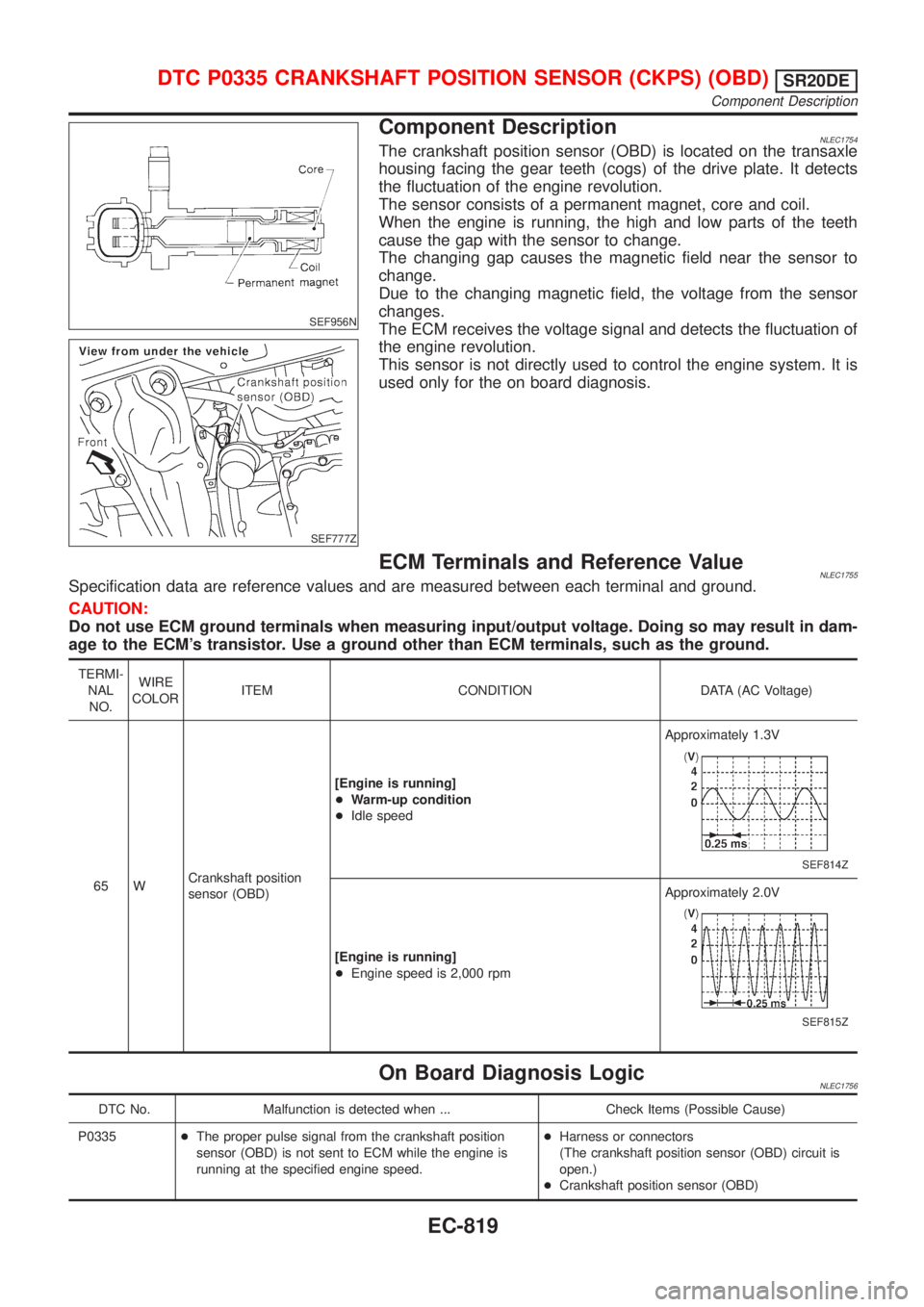
Component DescriptionNLEC1754The crankshaft position sensor (OBD) is located on the transaxle
housing facing the gear teeth (cogs) of the drive plate. It detects
the fluctuation of the engine revolution.
The sensor consists of a permanent magnet, core and coil.
When the engine is running, the high and low parts of the teeth
cause the gap with the sensor to change.
The changing gap causes the magnetic field near the sensor to
change.
Due to the changing magnetic field, the voltage from the sensor
changes.
The ECM receives the voltage signal and detects the fluctuation of
the engine revolution.
This sensor is not directly used to control the engine system. It is
used only for the on board diagnosis.
ECM Terminals and Reference ValueNLEC1755Specification data are reference values and are measured between each terminal and ground.
CAUTION:
Do not use ECM ground terminals when measuring input/output voltage. Doing so may result in dam-
age to the ECM's transistor. Use a ground other than ECM terminals, such as the ground.
TERMI-
NAL
NO.WIRE
COLORITEM CONDITION DATA (AC Voltage)
65 WCrankshaft position
sensor (OBD)[Engine is running]
+Warm-up condition
+Idle speedApproximately 1.3V
SEF814Z
[Engine is running]
+Engine speed is 2,000 rpmApproximately 2.0V
SEF815Z
On Board Diagnosis LogicNLEC1756
DTC No. Malfunction is detected when ... Check Items (Possible Cause)
P0335+The proper pulse signal from the crankshaft position
sensor (OBD) is not sent to ECM while the engine is
running at the specified engine speed.+Harness or connectors
(The crankshaft position sensor (OBD) circuit is
open.)
+Crankshaft position sensor (OBD)
DTC P0335 CRANKSHAFT POSITION SENSOR (CKPS) (OBD)SR20DE
Component Description
EC-819
Page 1276 of 3051

6 CHECK IGNITION SPARK
1. Turn Ignition switch ªOFFº.
2. Disconnect ignition wire from spark plug.
3. Connect a known good spark plug to the ignition wire.
4. Place end of spark plug against a suitable ground and crank engine.
5. Check for spark.
SEF282G
OK or NG
OK©GO TO 8.
NG©GO TO 7.
7 CHECK IGNITION WIRES
Refer to ªComponent Inspectionº, EC-814.
OK or NG
OK©Check distributor rotor head for incorrect parts. Check ignition coil, power transistor and
their circuits. Refer to EC-1004.
NG©Replace.
8 CHECK INJECTOR
1. Turn ignition switch ªOFFº.
2. Remove injector assembly. Refer to EC-578.
Keep fuel hose and all injectors connected to injector gallery.
3. Disconnect camshaft position sensor harness connector.
4. Turn ignition switch ªONº.
Make sure fuel does not drip from injector.
OK or NG
OK (Does not drip)©GO TO 9.
NG (Drips)©Replace the injector(s) from which fuel is dripping.
9 CHECK INTERMITTENT INCIDENT
Perform ªTROUBLE DIAGNOSIS FOR INTERMITTENT INCIDENTº, EC-670.
Trouble is fixed©INSPECTION END
Trouble is not fixed©Replace three way catalyst.
DTC P0420 THREE WAY CATALYST FUNCTIONSR20DE
Diagnostic Procedure (Cont'd)
EC-851
Page 1308 of 3051
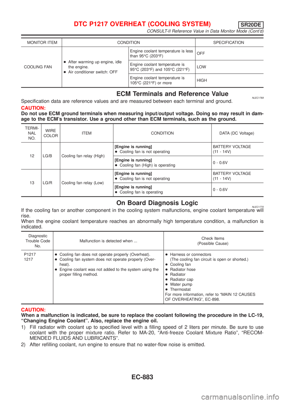
MONITOR ITEM CONDITION SPECIFICATION
COOLING FAN+After warming up engine, idle
the engine.
+Air conditioner switch: OFFEngine coolant temperature is less
than 95ÉC (203ÉF)OFF
Engine coolant temperature is
95ÉC (203ÉF) and 105ÉC (221ÉF)LOW
Engine coolant temperature is
105ÉC (221ÉF) or moreHIGH
ECM Terminals and Reference ValueNLEC1769Specification data are reference values and are measured between each terminal and ground.
CAUTION:
Do not use ECM ground terminals when measuring input/output voltage. Doing so may result in dam-
age to the ECM's transistor. Use a ground other than ECM terminals, such as the ground.
TERMI-
NAL
NO.WIRE
COLORITEM CONDITION DATA (DC Voltage)
12 LG/B Cooling fan relay (High)[Engine is running]
+Cooling fan is not operatingBATTERY VOLTAGE
(11 - 14V)
[Engine is running]
+Cooling fan (High) is operating0 - 0.6V
13 LG/R Cooling fan relay (Low)[Engine is running]
+Cooling fan is not operatingBATTERY VOLTAGE
(11 - 14V)
[Engine is running]
+Cooling fan is operating0 - 0.6V
On Board Diagnosis LogicNLEC1770If the cooling fan or another component in the cooling system malfunctions, engine coolant temperature will
rise.
When the engine coolant temperature reaches an abnormally high temperature condition, a malfunction is
indicated.
Diagnostic
Trouble Code
No.Malfunction is detected when ...Check Items
(Possible Cause)
P1217
1217+Cooling fan does not operate properly (Overheat).
+Cooling fan system does not operate properly (Over-
heat).
+Engine coolant was not added to the system using the
proper filling method.+Harness or connectors
(The cooling fan circuit is open or shorted.)
+Cooling fan
+Radiator hose
+Radiator
+Radiator cap
+Water pump
+Thermostat
For more information, refer to ªMAIN 12 CAUSES
OF OVERHEATINGº, EC-898.
CAUTION:
When a malfunction is indicated, be sure to replace the coolant following the procedure in the LC-19,
ªChanging Engine Coolantº. Also, replace the engine oil.
1) Fill radiator with coolant up to specified level with a filling speed of 2 liters per minute. Be sure to use
coolant with the proper mixture ratio. Refer to MA-20, ªAnti-freeze Coolant Mixture Ratioº, ªRECOM-
MENDED FLUIDS AND LUBRICANTSº.
2) After refilling coolant, run engine to ensure that no water-flow noise is emitted.
DTC P1217 OVERHEAT (COOLING SYSTEM)SR20DE
CONSULT-II Reference Value in Data Monitor Mode (Cont'd)
EC-883
Page 1330 of 3051

Diagnostic ProcedureNLEC1915
1 CHECK ENGINE START
Turn ignition switch ªOFFº, and restart engine.
Is engine running?
YesorNo
Ye s©GO TO 7.
No©GO TO 2.
2 CHECK POWER SUPPLY
1. Turn ignition switch ªOFFº.
2. Disconnect ignition coil harness connector.
SEF211X
3. Turn ignition switch ªONº.
4. Check voltage between ignition coil terminal 8 and ground with CONSULT-II or tester.
SEF257W
Voltage: Battery voltage
OK or NG
OK©GO TO 4.
NG©GO TO 3.
3 DETECT MALFUNCTIONING PART
Check the following.
+Harness connectors E76, F36
+ECM relay
+15A fuse
+Harness for open or short between ignition coil and fuse
©Repair harness or connectors.
DTC P1320 IGNITION SIGNALSR20DE
Diagnostic Procedure
EC-905
Page 1331 of 3051
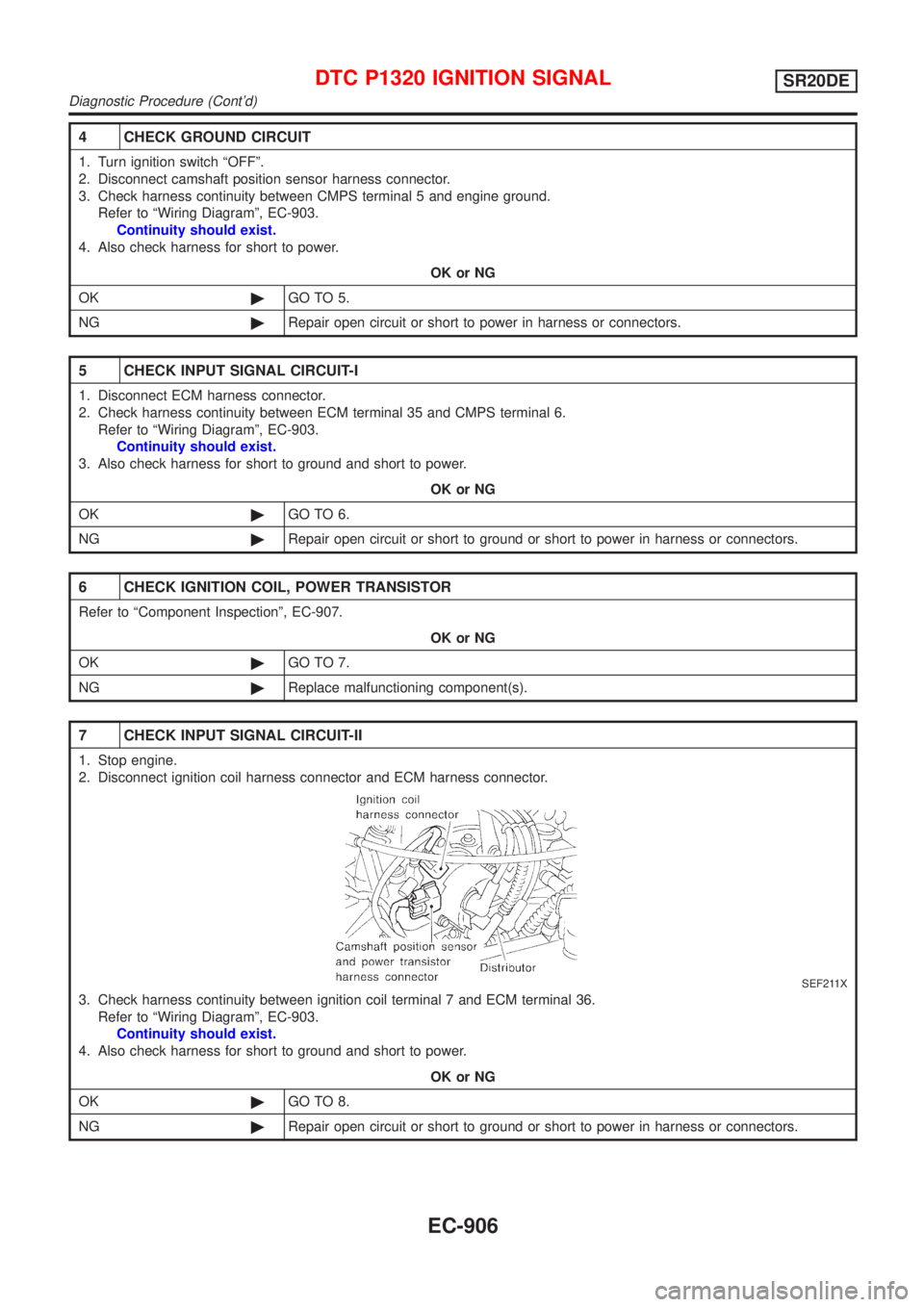
4 CHECK GROUND CIRCUIT
1. Turn ignition switch ªOFFº.
2. Disconnect camshaft position sensor harness connector.
3. Check harness continuity between CMPS terminal 5 and engine ground.
Refer to ªWiring Diagramº, EC-903.
Continuity should exist.
4. Also check harness for short to power.
OK or NG
OK©GO TO 5.
NG©Repair open circuit or short to power in harness or connectors.
5 CHECK INPUT SIGNAL CIRCUIT-I
1. Disconnect ECM harness connector.
2. Check harness continuity between ECM terminal 35 and CMPS terminal 6.
Refer to ªWiring Diagramº, EC-903.
Continuity should exist.
3. Also check harness for short to ground and short to power.
OK or NG
OK©GO TO 6.
NG©Repair open circuit or short to ground or short to power in harness or connectors.
6 CHECK IGNITION COIL, POWER TRANSISTOR
Refer to ªComponent Inspectionº, EC-907.
OK or NG
OK©GO TO 7.
NG©Replace malfunctioning component(s).
7 CHECK INPUT SIGNAL CIRCUIT-II
1. Stop engine.
2. Disconnect ignition coil harness connector and ECM harness connector.
SEF211X
3. Check harness continuity between ignition coil terminal 7 and ECM terminal 36.
Refer to ªWiring Diagramº, EC-903.
Continuity should exist.
4. Also check harness for short to ground and short to power.
OK or NG
OK©GO TO 8.
NG©Repair open circuit or short to ground or short to power in harness or connectors.
DTC P1320 IGNITION SIGNALSR20DE
Diagnostic Procedure (Cont'd)
EC-906
Page 1332 of 3051
8 CHECK RESISTOR
Refer to ªComponent Inspectionº EC-908.
OK or NG
OK©GO TO 9.
NG©Replace distributor cap.
9 CHECK INTERMITTENT INCIDENT
Perform ªTROUBLE DIAGNOSIS FOR INTERMITTENT INCIDENTº, EC-670.
©INSPECTION END
SEF237X
SEF238X
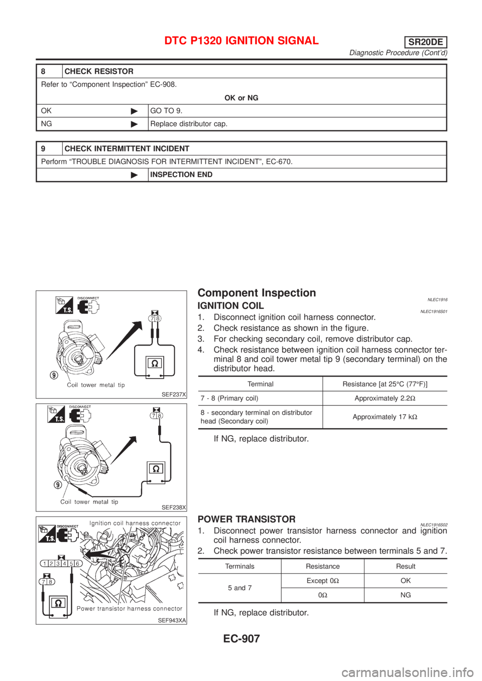
Component InspectionNLEC1916IGNITION COILNLEC1916S011. Disconnect ignition coil harness connector.
2. Check resistance as shown in the figure.
3. For checking secondary coil, remove distributor cap.
4. Check resistance between ignition coil harness connector ter-
minal 8 and coil tower metal tip 9 (secondary terminal) on the
distributor head.
Terminal Resistance [at 25ÉC (77ÉF)]
7 - 8 (Primary coil) Approximately 2.2W
8 - secondary terminal on distributor
head (Secondary coil)Approximately 17 kW
If NG, replace distributor.
SEF943XA
POWER TRANSISTORNLEC1916S021. Disconnect power transistor harness connector and ignition
coil harness connector.
2. Check power transistor resistance between terminals 5 and 7.
Terminals Resistance Result
5 and 7Except 0WOK
0WNG
If NG, replace distributor.
DTC P1320 IGNITION SIGNALSR20DE
Diagnostic Procedure (Cont'd)
EC-907
Page 1433 of 3051

Diagnostic ProcedureNLEC1928
1 CHECK ENGINE START
Turn ignition switch ªOFFº, and restart engine.
Is engine running?
YesorNo
Ye s©GO TO 7.
No©GO TO 2.
2 CHECK POWER SUPPLY
1. Turn ignition switch ªOFFº.
2. Disconnect ignition coil harness connector.
SEF211X
3. Turn ignition switch ªONº.
4. Check voltage between ignition coil terminal 8 and ground with CONSULT-II or tester.
SEF257W
Voltage: Battery voltage
OK or NG
OK©GO TO 4.
NG©GO TO 3.
3 DETECT MALFUNCTIONING PART
Check the following.
+Harness connectors E76, F36
+ECM relay
+15A fuse
+Harness for open or short between ignition coil and fuse
©Repair harness or connectors.
IGNITION SIGNALSR20DE
Diagnostic Procedure
EC-1008