torque NISSAN ALMERA TINO 2001 Service Service Manual
[x] Cancel search | Manufacturer: NISSAN, Model Year: 2001, Model line: ALMERA TINO, Model: NISSAN ALMERA TINO 2001Pages: 3051, PDF Size: 46.38 MB
Page 272 of 3051
NBR375
InstallationNLBR0043CAUTION:
+Refill with new brake fluid“DOT 4”.
+Never reuse drained brake fluid.
1. Install caliper assembly.
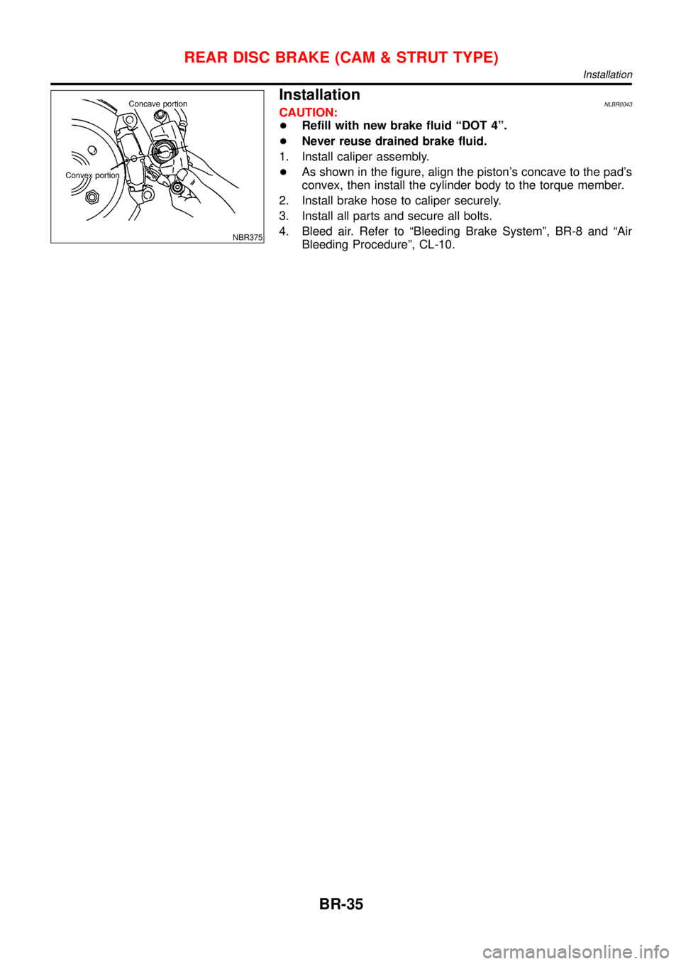
+As shown in the figure, align the piston’s concave to the pad’s
convex, then install the cylinder body to the torque member.
2. Install brake hose to caliper securely.
3. Install all parts and secure all bolts.
4. Bleed air. Refer to“Bleeding Brake System”, BR-8 and“Air
Bleeding Procedure”, CL-10.
REAR DISC BRAKE (CAM & STRUT TYPE)
Installation
BR-35
Page 273 of 3051
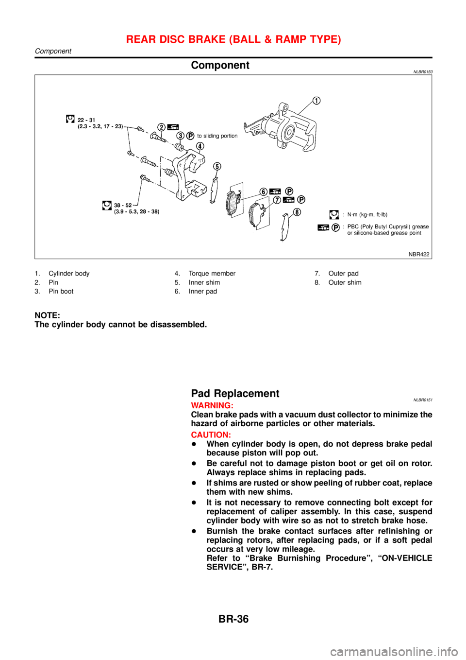
ComponentNLBR0150
NBR422
1. Cylinder body
2. Pin
3. Pin boot4. Torque member
5. Inner shim
6. Inner pad7. Outer pad
8. Outer shim
NOTE:
The cylinder body cannot be disassembled.
Pad ReplacementNLBR0151WARNING:
Clean brake pads with a vacuum dust collector to minimize the
hazard of airborne particles or other materials.
CAUTION:
+When cylinder body is open, do not depress brake pedal
because piston will pop out.
+Be careful not to damage piston boot or get oil on rotor.
Always replace shims in replacing pads.
+If shims are rusted or show peeling of rubber coat, replace
them with new shims.
+It is not necessary to remove connecting bolt except for
replacement of caliper assembly. In this case, suspend
cylinder body with wire so as not to stretch brake hose.
+Burnish the brake contact surfaces after refinishing or
replacing rotors, after replacing pads, or if a soft pedal
occurs at very low mileage.
Refer to“Brake Burnishing Procedure”,“ON-VEHICLE
SERVICE”, BR-7.
REAR DISC BRAKE (BALL & RAMP TYPE)
Component
BR-36
Page 274 of 3051
NBR423
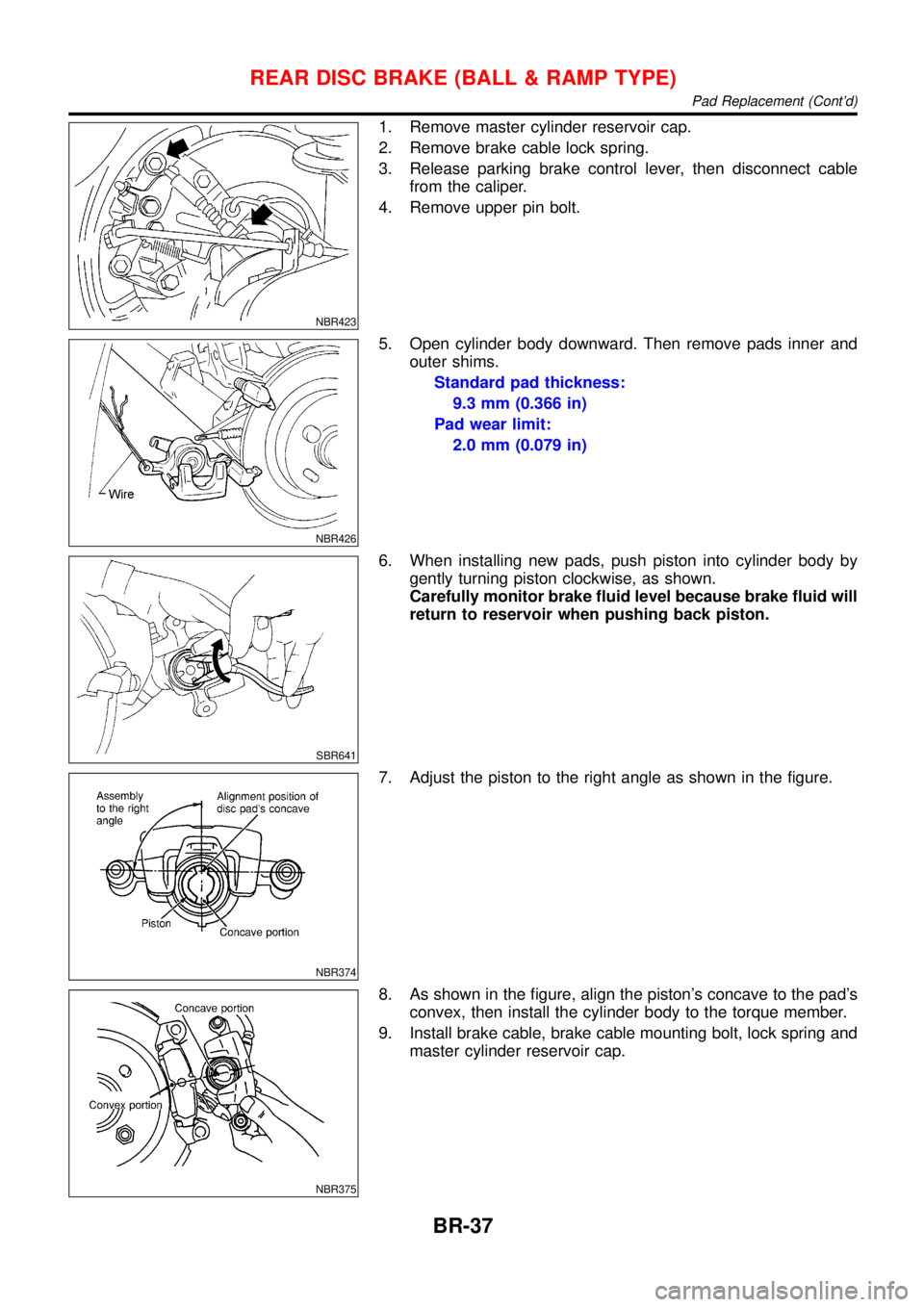
1. Remove master cylinder reservoir cap.
2. Remove brake cable lock spring.
3. Release parking brake control lever, then disconnect cable
from the caliper.
4. Remove upper pin bolt.
NBR426
5. Open cylinder body downward. Then remove pads inner and
outer shims.
Standard pad thickness:
9.3 mm (0.366 in)
Pad wear limit:
2.0 mm (0.079 in)
SBR641
6. When installing new pads, push piston into cylinder body by
gently turning piston clockwise, as shown.
Carefully monitor brake fluid level because brake fluid will
return to reservoir when pushing back piston.
NBR374
7. Adjust the piston to the right angle as shown in the figure.
NBR375
8. As shown in the figure, align the piston’s concave to the pad’s
convex, then install the cylinder body to the torque member.
9. Install brake cable, brake cable mounting bolt, lock spring and
master cylinder reservoir cap.
REAR DISC BRAKE (BALL & RAMP TYPE)
Pad Replacement (Cont’d)
BR-37
Page 275 of 3051
NBR427
RemovalNLBR0152WARNING:
Clean brake pads with a vacuum dust collector to minimize the
hazard of airborne particles or other materials.
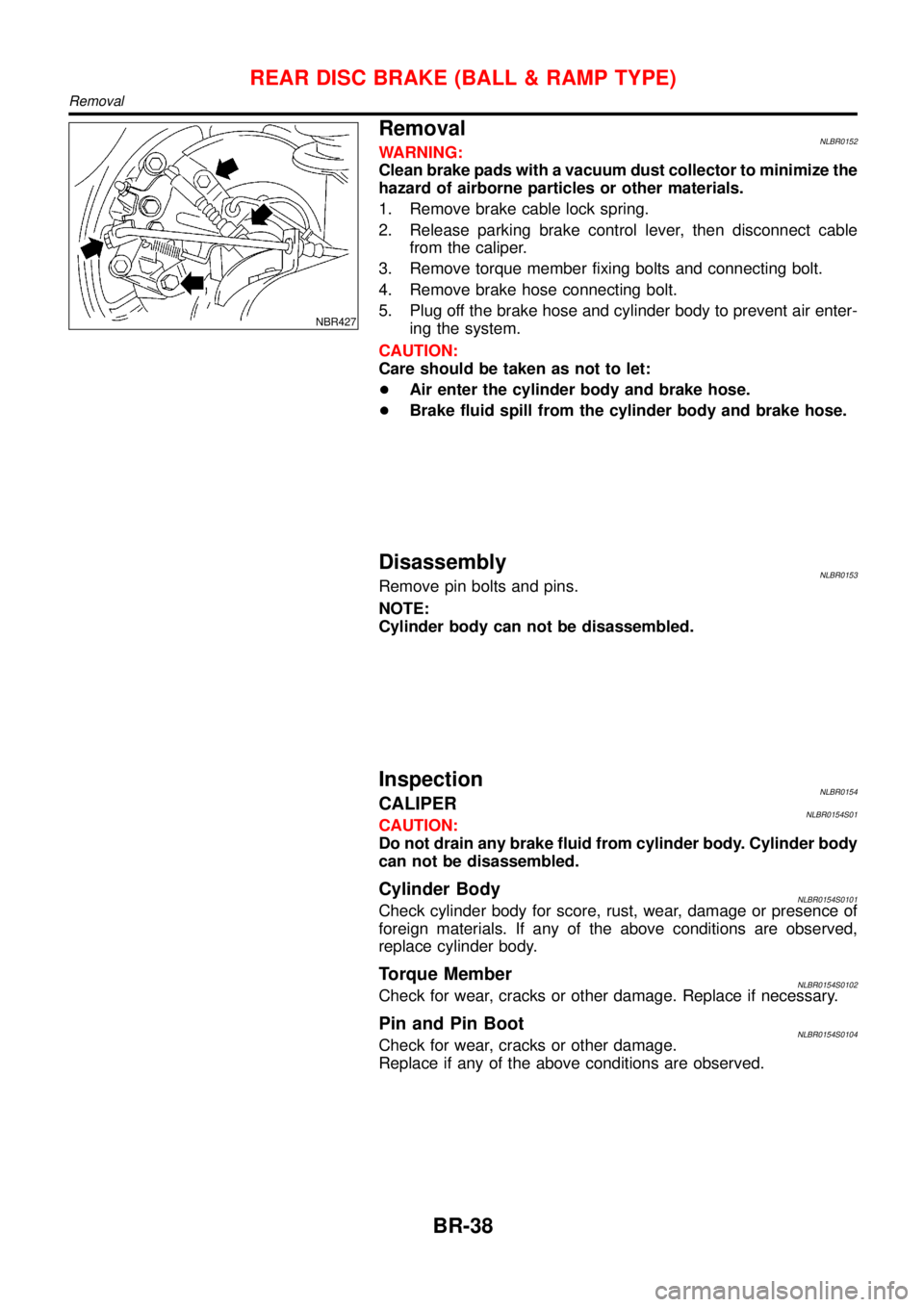
1. Remove brake cable lock spring.
2. Release parking brake control lever, then disconnect cable
from the caliper.
3. Remove torque member fixing bolts and connecting bolt.
4. Remove brake hose connecting bolt.
5. Plug off the brake hose and cylinder body to prevent air enter-
ing the system.
CAUTION:
Care should be taken as not to let:
+Air enter the cylinder body and brake hose.
+Brake fluid spill from the cylinder body and brake hose.
DisassemblyNLBR0153Remove pin bolts and pins.
NOTE:
Cylinder body can not be disassembled.
InspectionNLBR0154CALIPERNLBR0154S01CAUTION:
Do not drain any brake fluid from cylinder body. Cylinder body
can not be disassembled.
Cylinder BodyNLBR0154S0101Check cylinder body for score, rust, wear, damage or presence of
foreign materials. If any of the above conditions are observed,
replace cylinder body.
Torque MemberNLBR0154S0102Check for wear, cracks or other damage. Replace if necessary.
Pin and Pin BootNLBR0154S0104Check for wear, cracks or other damage.
Replace if any of the above conditions are observed.
REAR DISC BRAKE (BALL & RAMP TYPE)
Removal
BR-38
Page 276 of 3051
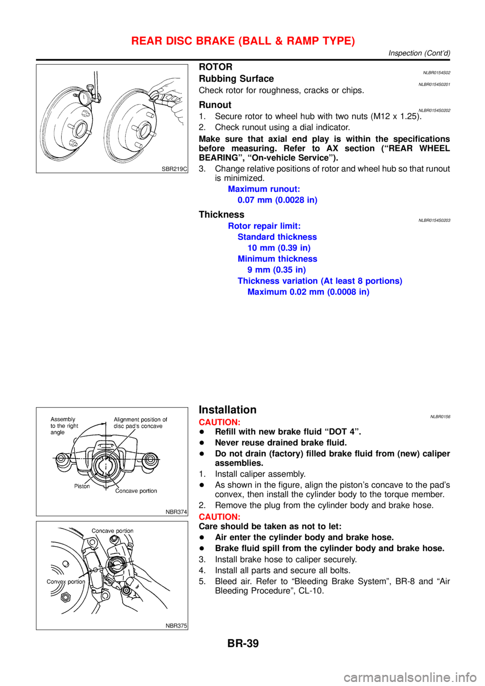
SBR219C
ROTORNLBR0154S02Rubbing SurfaceNLBR0154S0201Check rotor for roughness, cracks or chips.
RunoutNLBR0154S02021. Secure rotor to wheel hub with two nuts (M12 x 1.25).
2. Check runout using a dial indicator.
Make sure that axial end play is within the specifications
before measuring. Refer to AX section (“REAR WHEEL
BEARING”,“On-vehicle Service”).
3. Change relative positions of rotor and wheel hub so that runout
is minimized.
Maximum runout:
0.07 mm (0.0028 in)
ThicknessNLBR0154S0203Rotor repair limit:
Standard thickness
10 mm (0.39 in)
Minimum thickness
9 mm (0.35 in)
Thickness variation (At least 8 portions)
Maximum 0.02 mm (0.0008 in)
NBR374
NBR375
InstallationNLBR0156CAUTION:
+Refill with new brake fluid“DOT 4”.
+Never reuse drained brake fluid.
+Do not drain (factory) filled brake fluid from (new) caliper
assemblies.
1. Install caliper assembly.
+As shown in the figure, align the piston’s concave to the pad’s
convex, then install the cylinder body to the torque member.
2. Remove the plug from the cylinder body and brake hose.
CAUTION:
Care should be taken as not to let:
+Air enter the cylinder body and brake hose.
+Brake fluid spill from the cylinder body and brake hose.
3. Install brake hose to caliper securely.
4. Install all parts and secure all bolts.
5. Bleed air. Refer to“Bleeding Brake System”, BR-8 and“Air
Bleeding Procedure”, CL-10.
REAR DISC BRAKE (BALL & RAMP TYPE)
Inspection (Cont’d)
BR-39
Page 404 of 3051
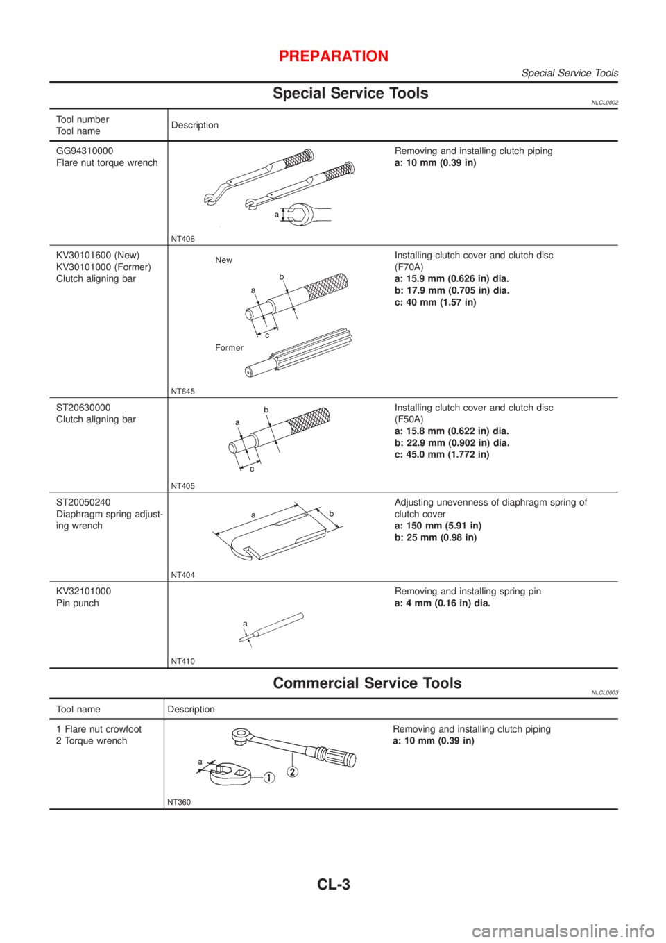
Special Service ToolsNLCL0002
Tool number
Tool nameDescription
GG94310000
Flare nut torque wrench
NT406
Removing and installing clutch piping
a: 10 mm (0.39 in)
KV30101600 (New)
KV30101000 (Former)
Clutch aligning bar
NT645
Installing clutch cover and clutch disc
(F70A)
a: 15.9 mm (0.626 in) dia.
b: 17.9 mm (0.705 in) dia.
c: 40 mm (1.57 in)
ST20630000
Clutch aligning bar
NT405
Installing clutch cover and clutch disc
(F50A)
a: 15.8 mm (0.622 in) dia.
b: 22.9 mm (0.902 in) dia.
c: 45.0 mm (1.772 in)
ST20050240
Diaphragm spring adjust-
ing wrench
NT404
Adjusting unevenness of diaphragm spring of
clutch cover
a: 150 mm (5.91 in)
b: 25 mm (0.98 in)
KV32101000
Pin punch
NT410
Removing and installing spring pin
a: 4 mm (0.16 in) dia.
Commercial Service ToolsNLCL0003
Tool name Description
1 Flare nut crowfoot
2 Torque wrench
NT360
Removing and installing clutch piping
a: 10 mm (0.39 in)
PREPARATION
Special Service Tools
CL-3
Page 411 of 3051

CLUTCH PEDAL ADJUSTMENTNLCL0006S01Pedal StrokeNLCL0006S01011. Loosen the pedal stopper bolt completely (so there is no con-
tact between pedal and stopper bolt).
2. Adjust pedal stroke to the specified value with the master cyl-
inder push rod.
3. Adjust the pedal stopper bolt until it is just in contact with the
pedal, then tighten the lock nut.
4. Once stroke is set to specification, adjust clutch pedal free
play.
Pedal stroke ªSº.
Refer to ªSDSº, CL-24.
Pedal Free PlayNLCL0006S01021. Adjust pedal free play to the specified value with the master
cylinder push rod.
2. Tighten lock nut of the master cylinder push rod.
+Push on the clutch pedal until resistance is felt, and check the
distance the pedal moves.
Pedal free play ªAº.
Refer to ªSDSº, CL-24.
SCL838
SCL839
AIR BLEEDING PROCEDURENLCL0006S021. Bleed air from clutch operating cylinder according to the fol-
lowing procedure.
+Carefully monitor fluid level at reservoir during bleeding
operation.
a. Top up reservoir with recommended brake fluid.
b. Connect a transparent vinyl tube to air bleeder valve.
c. Slowly depress the clutch pedal to its full stroke and release it
completely. Repeat this operation several times at 2 to 3 sec-
onds intervals.
d. Open the air bleeder with the clutch pedal fully depressed.
e. Close the air bleeder.
f. Release the clutch pedal and wait at least 5 seconds.
g. Repeat steps c through f mentioned above, until clear brake
fluid comes out of air bleeder valve.
Air bleeder valve tightening torque:
: 5.9 - 9.8 N´m (0.6 - 1.0 kg-m, 52 - 86 in-lb)
CLUTCH SYSTEM
Inspection and Adjustment (Cont'd)
CL-10
Page 413 of 3051

RemovalNLCL00081. Drain brake fluid.
CAUTION:
Be careful not to splash brake fluid on painted areas; it may
cause paint damage. If brake fluid is splashed on painted
areas, wash it away with water immediately.
2. Remove clutch tube using a flare nut wrench.
3. Remove snap pin between clutch pedal and push rod, and
remove clevis pin.
4. Unscrew master cylinder assembly mounting nuts and remove
master cylinder assembly from vehicle.
InstallationNLCL00091. Connect clutch tube to master cylinder assembly, and hand-
tighten flare nut.
2. Install master cylinder assembly to vehicle, and tighten mount-
ing nuts to the specified torque.
: 13 - 16 N´m (1.3 - 1.6 kg-m, 10 - 12 ft-lb)
3. Tighten clutch tube flare nut using a flare nut torque wrench.
: 15 - 18 N´m (1.5 - 1.8 kg-m, 11 - 13 ft-lb)
4. After installing clevis pin, install snap pin to connect clutch
pedal to push rod.
5. After finishing the operation, bleed air from clutch piping con-
nector and operating cylinder. (Refer to ªAir Bleeding
Procedureº, CL-10.)
SCL725
DisassemblyNLCL00101. Loosen push rod lock nut A to remove clevis and lock nut A.
2. Remove dust cover.
3. Remove stopper ring and stopper, and remove push rod from
cylinder body. During removal, keep push rod depressed, to
prevent piston inside master cylinder from popping out.
4. Remove piston assembly from cylinder body.
InspectionNLCL0011Check the following items, and replace if necessary.
+Rubbing surface of cylinder and piston, for uneven wear, rust
or damage
+Piston with piston cup, for wear or damage
+Return spring, for wear or damage
+Dust cover, for cracks, deformation or damage
+Reservoir, for deformation or damage
CLUTCH MASTER CYLINDER
Removal
CL-12
Page 414 of 3051

AssemblyNLCL00121. Apply rubber lubricant to the sliding part of piston assembly,
and insert piston assembly.
2. After installing stopper to push rod, install stopper ring while
keeping piston assembly depressed by hand, so that piston
assembly will not pop out.
CAUTION:
Stopper ring cannot be reused. Always use a new stopper ring
for assembly.
3. Install dust cover.
4. Install clevis to push rod, and tighten lock nut A to the speci-
fied torque.
:8-10N´m(0.8 - 1.1 kg-m, 70 - 95 in-lb)
5. Install spring pin using a pin punch.
CLUTCH MASTER CYLINDER
Assembly
CL-13
Page 417 of 3051

SCL729
RemovalNLCL00421. Remove fuel filter mounting bracket.
2. Remove air cleaner and air duct.
3. Drain brake fluid.
CAUTION:
Be careful not to splash brake fluid on painted areas; it may
cause paint damage. If brake fluid is splashed on painted
areas, wash it away with water immediately.
4. Remove flare nut using a flare nut wrench.
5. Remove clutch hose and clutch tube.
SCL730
InstallationNLCL00431. When installing clutch hose to bracket, face lock plate in the
correct direction as shown to secure clutch hose.
CAUTION:
Install clutch hose without twisting or bending it.
2. Tighten flare nut to the specified torque, using a flare nut
wrench.
: 15 - 18 N´m (1.5 - 1.8 kg-m, 11 - 13 ft-lb)
CAUTION:
Be careful not to damage flare nut and clutch tube.
3. Install clutch hose to operating cylinder, and tighten mounting
bolts to the specified torque.
: 17 - 19 N´m (1.7 - 2.0 kg-m, 13 - 14 ft-lb)
4. After finishing the operation, bleed air from the clutch piping.
Refer to ªBleeding Procedureº, CL-10.
PIPING
Removal
CL-16