belt NISSAN ALMERA TINO 2001 Service Repair Manual
[x] Cancel search | Manufacturer: NISSAN, Model Year: 2001, Model line: ALMERA TINO, Model: NISSAN ALMERA TINO 2001Pages: 3051, PDF Size: 46.38 MB
Page 2 of 3051
AUTOMATIC TRANSAXLE
SECTION
AT
CONTENTS
EURO-OBD
TROUBLE DIAGNOSIS - INDEX....................................4
Alphabetical & P No. Index for DTC ...........................4
PRECAUTIONS...............................................................6
Precautions for Supplemental Restraint System
(SRS)²AIR BAG²and²SEAT BELT
PRE-TENSIONER²......................................................6
Precautions for On Board Diagnostic (EURO-
OBD) System of CVT and Engine...............................6
Precautions ..................................................................6
Service Notice or Precautions .....................................7
Wiring Diagrams and Trouble Diagnoses....................8
PREPARATION...............................................................9
Special Service Tools ..................................................9
CVT FLUID.....................................................................10
Checking CVT Fluid...................................................10
Changing CVT Fluid .................................................. 11
OVERALL SYSTEM......................................................12
CVT Electrical Parts Location....................................12
Circuit Diagram ..........................................................13
Cross-sectional View - RE0F06A ..............................14
Control System ..........................................................15
EURO-OBD
ON BOARD DIAGNOSTIC SYSTEM
DESCRIPTION...............................................................18
Introduction ................................................................18
EURO-OBD Function for CVT System......................18
EURO-OBD Diagnostic Trouble Code (DTC)............18
Malfunction Indicator (MI) ..........................................21
CONSULT-II ...............................................................21
EXCEPT FOR EURO-OBD
ON BOARD DIAGNOSTIC SYSTEM
DESCRIPTION...............................................................31CONSULT-II ...............................................................31
Diagnostic Procedure Without CONSULT-II ..............35
EURO-OBD
TROUBLE DIAGNOSIS - INTRODUCTION..................41
Introduction ................................................................41
Work Flow ..................................................................44
EXCEPT FOR EURO-OBD
TROUBLE DIAGNOSIS - INTRODUCTION..................46
Introduction ................................................................46
Work Flow ..................................................................49
TROUBLE DIAGNOSIS - BASIC INSPECTION...........51
CVT Fluid Check .......................................................51
Stall Test ....................................................................51
Line Pressure Test .....................................................52
Road Test...................................................................53
TROUBLE DIAGNOSIS - GENERAL
DESCRIPTION...............................................................58
TCM Terminals and Reference Value........................58
TROUBLE DIAGNOSIS FOR POWER SUPPLY..........62
Wiring Diagram - AT - MAIN ......................................62
TCM Terminals and Reference Value........................64
Diagnostic Procedure ................................................65
EURO-OBD
DTC P0705 PARK/NEUTRAL POSITION (PNP)
SWITCH.........................................................................66
Description .................................................................66
Wiring Diagram - AT - PNP/SW.................................68
Diagnostic Procedure ................................................70
Component Inspection ...............................................72
DTC P0710 CVT FLUID TEMPERATURE SENSOR
CIRCUIT.........................................................................73
Description .................................................................73
Page 7 of 3051
Precautions for Supplemental Restraint System
(SRS) ªAIR BAGº and ªSEAT BELT
PRE-TENSIONERº
NLAT0002The Supplemental Restraint System ªAIR BAGº and ªSEAT BELT PRE-TENSIONERº, used along with a seat
belt, help to reduce the risk or severity of injury to the driver and front passenger in a frontal collision. The
Supplemental Restraint System consists of air bag modules (located in the center of the steering wheel and
on the instrument panel on the passenger side), seat belt pre-tensioners, a diagnosis sensor unit, warning
lamp, wiring harness and spiral cable.
In addition to the supplemental air bag modules for a frontal collision, the supplemental side air bag used along
with the seat belt helps to reduce the risk or severity of injury to the driver and front passenger in a side col-
lision. The supplemental side air bag consists of air bag modules (located in the outer side of front seats),
satellite sensor, diagnosis sensor unit (one of components of supplemental air bags for a frontal collision),
wiring harness, warning lamp (one of components of supplemental air bags for a frontal collision). Information
necessary to service the system safely is included in theRS sectionof this Service Manual.
WARNING:
+To avoid rendering the SRS inoperative, which could increase the risk of personal injury or death
in the event of a collision which would result in air bag inflation, all maintenance must be performed
by an authorized NISSAN dealer.
+Improper maintenance, including incorrect removal and installation of the SRS, can lead to per-
sonal injury caused by unintentional activation of the system.
+Do not use electrical test equipment on any circuit related to the SRS unless instructed to in this
Service Manual. SRS wiring harnesses can be identified with yellow harness connector (and with
yellow harness protector or yellow insulation tape before the harness connectors).
Precautions for On Board Diagnostic (EURO-
OBD) System of CVT and Engine
NLAT0198The ECM has an on board diagnostic system. It will light up the malfunction indicator lamp (MI) to warn the
driver of a malfunction causing emission deterioration.
CAUTION:
+Be sure to turn the ignition switch ªOFFº and disconnect the negative battery terminal before any
repair or inspection work. The open/short circuit of related switches, sensors, solenoid valves, etc.
will cause the MI to light up.
+Be sure to connect and lock the connectors securely after work. A loose (unlocked) connector will
cause the MI to light up due to an open circuit. (Be sure the connector is free from water, grease,
dirt, bent terminals, etc.)
+Be sure to route and secure the harnesses properly after work. Interference of the harness with a
bracket, etc. may cause the MI to light up due to a short circuit.
+Be sure to connect rubber tubes properly after work. A misconnected or disconnected rubber tube
may cause the MI to light up due to a malfunction of the EGR system or fuel injection system, etc.
+Be sure to erase the unnecessary malfunction information (repairs completed) from the TCM and
ECM before returning the vehicle to the customer.
SEF289H
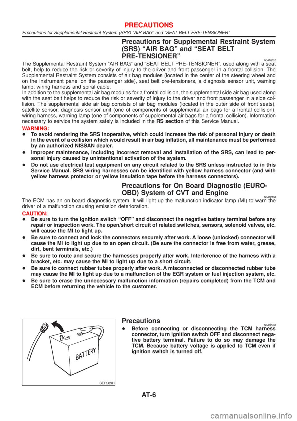
PrecautionsNLAT0003+Before connecting or disconnecting the TCM harness
connector, turn ignition switch OFF and disconnect nega-
tive battery terminal. Failure to do so may damage the
TCM. Because battery voltage is applied to TCM even if
ignition switch is turned off.
PRECAUTIONS
Precautions for Supplemental Restraint System (SRS) ªAIR BAGº and ªSEAT BELT PRE-TENSIONERº
AT-6
Page 238 of 3051
BRAKE SYSTEM
SECTION
BR
CONTENTS
PRECAUTIONS...............................................................3
Supplemental Restraint System (SRS)″AIR
BAG″and″SEAT BELT PRE-TENSIONER″...............3
Precautions for Brake System .....................................3
Precautions When Working On ABS ...........................4
Wiring Diagrams and Trouble Diagnosis .....................4
PREPARATION...............................................................5
Commercial Service Tools ...........................................5
NOISE, VIBRATION AND HARSHNESS (NVH)
TROUBLESHOOTING.....................................................6
NVH Troubleshooting Chart.........................................6
ON-VEHICLE SERVICE..................................................7
Checking Brake Fluid Level.........................................7
Checking Brake Line ...................................................7
Changing Brake Fluid ..................................................7
Brake Burnishing Procedure........................................7
Bleeding Brake System ...............................................8
BRAKE HYDRAULIC LINE.............................................9
Hydraulic Circuit...........................................................9
Removal .......................................................................9
Inspection.....................................................................9
Installation ..................................................................10
BRAKE PEDAL AND BRACKET.................................. 11
Removal and Installation ........................................... 11
Inspection................................................................... 11
Adjustment ................................................................. 11
MASTER CYLINDER.....................................................13
Removal .....................................................................13
Disassembly...............................................................13
Inspection...................................................................14
Assembly ...................................................................14
Installation ..................................................................15
BRAKE BOOSTER........................................................16
On-vehicle Service.....................................................16
OPERATING CHECK...............................................16
AIRTIGHT CHECK...................................................16
Removal .....................................................................16
Inspection...................................................................16
OUTPUT ROD LENGTH CHECK..............................16Installation ..................................................................17
VACUUM HOSE.............................................................18
Removal and Installation ...........................................18
Inspection...................................................................19
HOSES AND CONNECTORS...................................19
CHECK VALVE........................................................19
VACUUM PUMP............................................................20
Removal .....................................................................20
Installation ..................................................................21
Inspection...................................................................21
Component ................................................................22
Disassembly...............................................................22
Assembly ...................................................................22
FRONT DISC BRAKE...................................................24
Component ................................................................24
Pad Replacement ......................................................24
Removal .....................................................................25
Disassembly...............................................................25
Inspection...................................................................25
CALIPER.................................................................25
ROTOR...................................................................26
Assembly ...................................................................27
Installation ..................................................................27
REAR DISC BRAKE (CAM & STRUT TYPE)..............28
Component ................................................................28
Pad Replacement ......................................................28
Removal .....................................................................30
Disassembly...............................................................30
Inspection...................................................................31
CALIPER.................................................................31
ROTOR...................................................................32
Assembly ...................................................................32
Installation ..................................................................35
REAR DISC BRAKE (BALL & RAMP TYPE)..............36
Component ................................................................36
Pad Replacement ......................................................36
Removal .....................................................................38
Disassembly...............................................................38
Inspection...................................................................38
Page 240 of 3051
Supplemental Restraint System (SRS)“AIR
BAG”and“SEAT BELT PRE-TENSIONER”
NLBR0081The Supplemental Restraint System such as “AIR BAG” and “SEAT BELT PRE-TENSIONER” used along with
a seat belt, helps to reduce the risk or severity of injury to the driver and front passenger for certain types of
collision. The SRS system composition which is available to NISSAN MODEL V10 is as follows (The compo-
sition varies according to the destination and optional equipment.):
+For a frontal collision
The Supplemental Restraint System consists of driver air bag module (located in the center of the steer-
ing wheel), front passenger air bag module (located on the instrument panel on passenger side), front seat
belt pre-tensioners, a diagnosis sensor unit, warning lamp, wiring harness and spiral cable.
+For a side collision
The Supplemental Restraint System consists of front side air bag module (located in the outer side of front
seat), side air bag (satellite) sensor, diagnosis sensor unit (one of components of air bags for a frontal
collision), wiring harness, warning lamp (one of components of air bags for a frontal collision).
Information necessary to service the system safely is included in theRS sectionof this Service Manual.
WARNING:
+To avoid rendering the SRS inoperative, which could increase the risk of personal injury or death
in the event of a collision which would result in air bag inflation, all maintenance should be per-
formed by an authorized NISSAN dealer.
+Improper maintenance, including incorrect removal and installation of the SRS, can lead to per-
sonal injury caused by unintentional activation of the system. For removal of Spiral Cable and Air
Bag Module, see the RS section.
+Do not use electrical test equipment on any circuit related to the SRS unless instructed to in this
Service Manual. Spiral cable and wiring harnesses covered with yellow insulation tape either just
before the harness connectors or for the complete harness are related to the SRS.
SBR686C
Precautions for Brake SystemNLBR0002+Recommended fluid is brake fluid“DOT 4”.
+Never reuse drained brake fluid.
+Be careful not to splash brake fluid on painted areas.
+To clean or wash all parts of master cylinder, disc brake
caliper and wheel cylinder, use clean brake fluid.
+Never use mineral oils such as gasoline or kerosene. They
will ruin rubber parts of the hydraulic system.
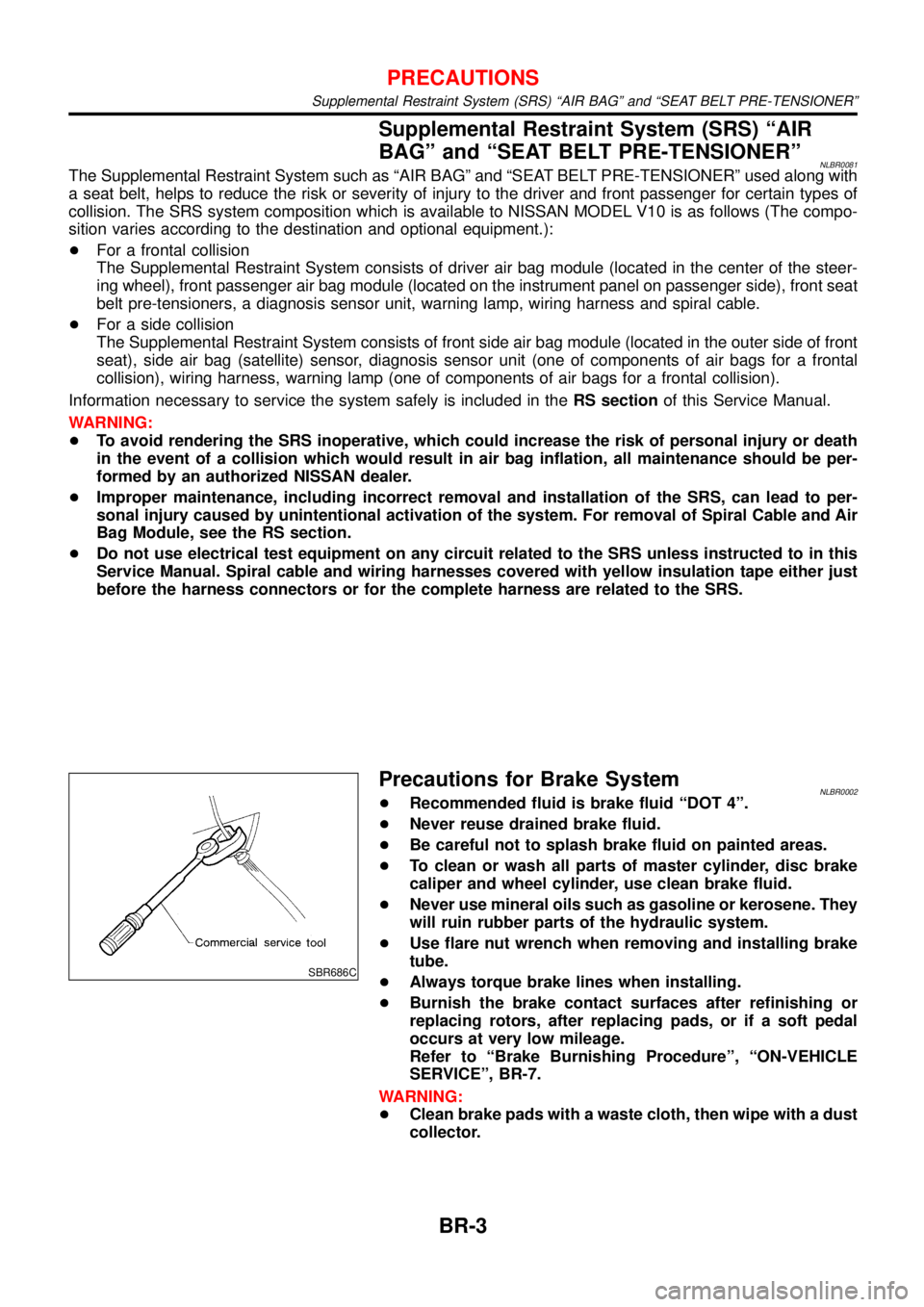
+Use flare nut wrench when removing and installing brake
tube.
+Always torque brake lines when installing.
+Burnish the brake contact surfaces after refinishing or
replacing rotors, after replacing pads, or if a soft pedal
occurs at very low mileage.
Refer to“Brake Burnishing Procedure”,“ON-VEHICLE
SERVICE”, BR-7.
WARNING:
+Clean brake pads with a waste cloth, then wipe with a dust
collector.
PRECAUTIONS
Supplemental Restraint System (SRS) “AIR BAG” and “SEAT BELT PRE-TENSIONER”
BR-3
Page 332 of 3051
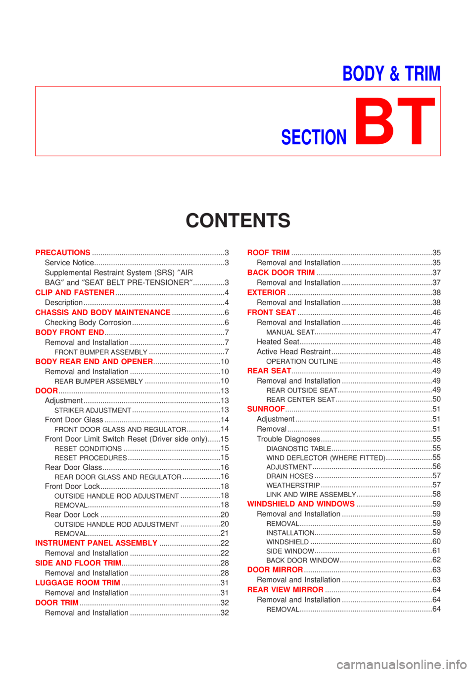
BODY & TRIM
SECTION
BT
CONTENTS
PRECAUTIONS...............................................................3
Service Notice..............................................................3
Supplemental Restraint System (SRS)²AIR
BAG²and²SEAT BELT PRE-TENSIONER²...............3
CLIP AND FASTENER....................................................4
Description ...................................................................4
CHASSIS AND BODY MAINTENANCE.........................6
Checking Body Corrosion ............................................6
BODY FRONT END.........................................................7
Removal and Installation .............................................7
FRONT BUMPER ASSEMBLY....................................7
BODY REAR END AND OPENER................................10
Removal and Installation ...........................................10
REAR BUMPER ASSEMBLY....................................10
DOOR.............................................................................13
Adjustment .................................................................13
STRIKER ADJUSTMENT..........................................13
Front Door Glass .......................................................14
FRONT DOOR GLASS AND REGULATOR................14
Front Door Limit Switch Reset (Driver side only)......15
RESET CONDITIONS..............................................15
RESET PROCEDURES............................................15
Rear Door Glass ........................................................16
REAR DOOR GLASS AND REGULATOR..................16
Front Door Lock .........................................................18
OUTSIDE HANDLE ROD ADJUSTMENT...................18
REMOVAL...............................................................18
Rear Door Lock .........................................................20
OUTSIDE HANDLE ROD ADJUSTMENT...................20
REMOVAL...............................................................21
INSTRUMENT PANEL ASSEMBLY.............................22
Removal and Installation ...........................................22
SIDE AND FLOOR TRIM...............................................28
Removal and Installation ...........................................28
LUGGAGE ROOM TRIM...............................................31
Removal and Installation ...........................................31
DOOR TRIM...................................................................32
Removal and Installation ...........................................32ROOF TRIM...................................................................35
Removal and Installation ...........................................35
BACK DOOR TRIM.......................................................37
Removal and Installation ...........................................37
EXTERIOR.....................................................................38
Removal and Installation ...........................................38
FRONT SEAT................................................................46
Removal and Installation ...........................................46
MANUAL SEAT........................................................47
Heated Seat ...............................................................48
Active Head Restraint ................................................48
OPERATION OUTLINE............................................48
REAR SEAT...................................................................49
Removal and Installation ...........................................49
REAR OUTSIDE SEAT.............................................49
REAR CENTER SEAT..............................................50
SUNROOF......................................................................51
Adjustment .................................................................51
Removal .....................................................................51
Trouble Diagnoses.....................................................55
DIAGNOSTIC TABLE................................................55
WIND DEFLECTOR (WHERE FITTED)......................55
ADJUSTMENT.........................................................56
DRAIN HOSES........................................................57
WEATHERSTRIP.....................................................57
LINK AND WIRE ASSEMBLY....................................58
WINDSHIELD AND WINDOWS....................................59
Removal and Installation ...........................................59
REMOVAL...............................................................59
INSTALLATION........................................................59
WINDSHIELD..........................................................60
SIDE WINDOW........................................................61
BACK DOOR WINDOW............................................62
DOOR MIRROR.............................................................63
Removal and Installation ...........................................63
REAR VIEW MIRROR...................................................64
Removal and Installation ...........................................64
REMOVAL...............................................................64
Page 334 of 3051
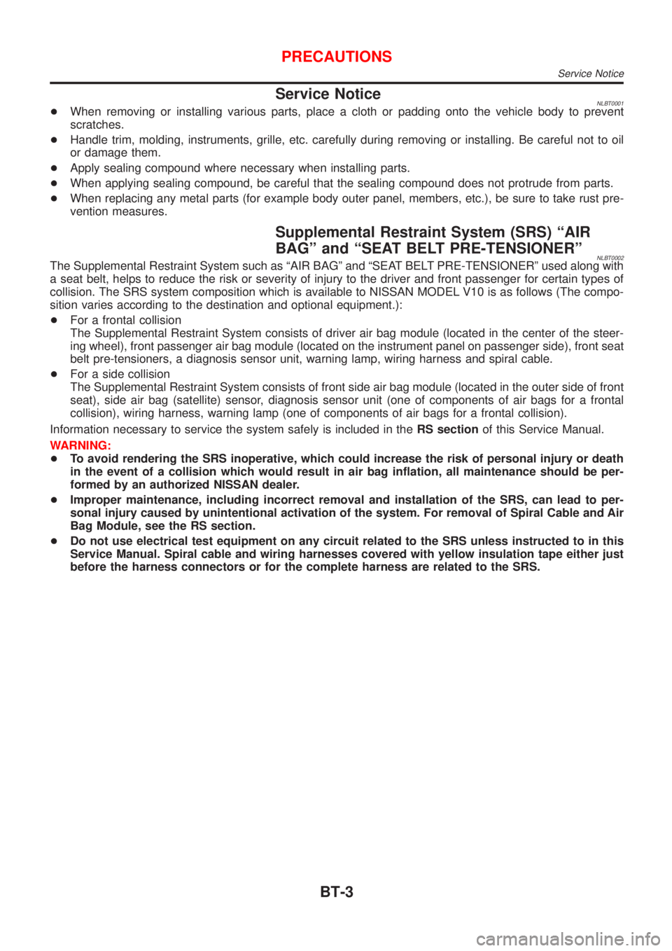
Service NoticeNLBT0001+When removing or installing various parts, place a cloth or padding onto the vehicle body to prevent
scratches.
+Handle trim, molding, instruments, grille, etc. carefully during removing or installing. Be careful not to oil
or damage them.
+Apply sealing compound where necessary when installing parts.
+When applying sealing compound, be careful that the sealing compound does not protrude from parts.
+When replacing any metal parts (for example body outer panel, members, etc.), be sure to take rust pre-
vention measures.
Supplemental Restraint System (SRS) ªAIR
BAGº and ªSEAT BELT PRE-TENSIONERº
NLBT0002The Supplemental Restraint System such as ªAIR BAGº and ªSEAT BELT PRE-TENSIONERº used along with
a seat belt, helps to reduce the risk or severity of injury to the driver and front passenger for certain types of
collision. The SRS system composition which is available to NISSAN MODEL V10 is as follows (The compo-
sition varies according to the destination and optional equipment.):
+For a frontal collision
The Supplemental Restraint System consists of driver air bag module (located in the center of the steer-
ing wheel), front passenger air bag module (located on the instrument panel on passenger side), front seat
belt pre-tensioners, a diagnosis sensor unit, warning lamp, wiring harness and spiral cable.
+For a side collision
The Supplemental Restraint System consists of front side air bag module (located in the outer side of front
seat), side air bag (satellite) sensor, diagnosis sensor unit (one of components of air bags for a frontal
collision), wiring harness, warning lamp (one of components of air bags for a frontal collision).
Information necessary to service the system safely is included in theRS sectionof this Service Manual.
WARNING:
+To avoid rendering the SRS inoperative, which could increase the risk of personal injury or death
in the event of a collision which would result in air bag inflation, all maintenance should be per-
formed by an authorized NISSAN dealer.
+Improper maintenance, including incorrect removal and installation of the SRS, can lead to per-
sonal injury caused by unintentional activation of the system. For removal of Spiral Cable and Air
Bag Module, see the RS section.
+Do not use electrical test equipment on any circuit related to the SRS unless instructed to in this
Service Manual. Spiral cable and wiring harnesses covered with yellow insulation tape either just
before the harness connectors or for the complete harness are related to the SRS.
PRECAUTIONS
Service Notice
BT-3
Page 359 of 3051
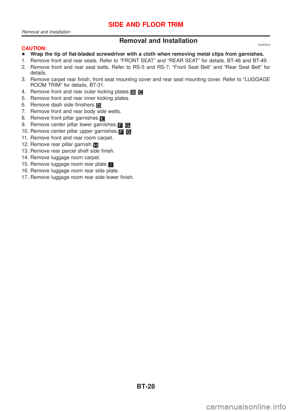
Removal and InstallationNLBT0013CAUTION:
+Wrap the tip of flat-bladed screwdriver with a cloth when removing metal clips from garnishes.
1. Remove front and rear seats. Refer to ªFRONT SEATº and ªREAR SEATº for details, BT-46 and BT-49.
2. Remove front and rear seat belts. Refer to RS-5 and RS-7, ªFront Seat Beltº and ªRear Seat Beltº for
details.
3. Remove carpet rear finish, front seat mounting cover and rear seat mounting cover. Refer to ªLUGGAGE
ROOM TRIMº for details, BT-31.
4. Remove front and rear outer kicking plates.
5. Remove front and rear inner kicking plates.
6. Remove dash side finishers.
7. Remove front and rear body side welts.
8. Remove front pillar garnishes.
9. Remove center pillar lower garnishes.
10. Remove center pillar upper garnishes.
11. Remove front and rear room carpet.
12. Remove rear pillar garnish.
13. Remove rear parcel shelf side finish.
14. Remove luggage room carpet.
15. Remove luggage room rear plate.
16. Remove luggage room rear side plate.
17. Remove luggage room rear side lower finish.
SIDE AND FLOOR TRIM
Removal and Installation
BT-28
Page 366 of 3051

Removal and InstallationNLBT00151. Remove rear seat.
2. Remove shoulder anchor bolts. Refer to RS-5, ªFront Seat Beltº for details.
3. Remove front pillar garnishes, center pillar upper garnishes, center pillar lower garnishes and rear pillar
garnishes. Refer to ªSIDE AND FLOOR TRIMº for details, BT-28.
4. Push back the front seat back.
5. Remove sunroof switch, then disconnect connectors. (Model with sunroof)
6. Remove front personal light then disconnect connector (Model without sunroof)
7. Remove sunroof welt. (Model with sunroof)
8. Remove interior lamp assembly, then disconnect connectors.
9. Remove sun visors.
10. Remove assist grips.
11. Remove clips securing headlining, then remove headlining from vehicle through back door side.
NBT113
ROOF TRIM
Removal and Installation
BT-35
Page 426 of 3051

ENGINE CONTROL SYSTEM
SECTION
EC
CONTENTS
QG18DE
TROUBLE DIAGNOSIS - INDEX..................................16
Alphabetical & P No. Index for DTC .........................16
PRECAUTIONS.............................................................21
Precautions for Supplemental Restraint System
(SRS)²AIR BAG²and²SEAT BELT
PRE-TENSIONER²....................................................21
Precautions for On Board Diagnostic (OBD)
System of Engine ......................................................21
Engine Fuel & Emission Control System ..................22
Wiring Diagrams and Trouble Diagnosis ...................24
PREPARATION.............................................................25
Special Service Tools ................................................25
Commercial Service Tools .........................................25
ENGINE AND EMISSION CONTROL OVERALL
SYSTEM.........................................................................26
Engine Control Component Parts Location ...............26
Circuit Diagram ..........................................................30
System Diagram ........................................................32
Vacuum Hose Drawing ..............................................33
System Chart .............................................................34
ENGINE AND EMISSION BASIC CONTROL
SYSTEM DESCRIPTION...............................................35
Multiport Fuel Injection (MFI) System .......................35
Electronic Ignition (EI) System ..................................37
Air Conditioning Cut Control ......................................38
Fuel Cut Control (at no load & high engine
speed) ........................................................................39
Evaporative Emission System ...................................39
Positive Crankcase Ventilation ..................................42
BASIC SERVICE PROCEDURE...................................43
Fuel Pressure Release ..............................................43
Fuel Pressure Check .................................................43
Fuel Pressure Regulator Check ................................44
Injector .......................................................................44
How to Check Idle Speed and Ignition Timing ..........46
Preparation ................................................................47
Inspection Procedure .................................................49Idle Air Volume Learning ...........................................57
ON BOARD DIAGNOSTIC SYSTEM
DESCRIPTION...............................................................59
Introduction ................................................................59
Two Trip Detection Logic ...........................................59
Emission-related Diagnostic Information ...................60
NATS (Nissan Anti-theft System) ..............................72
Malfunction Indicator (MI) ..........................................73
OBD System Operation Chart (With Euro-OBD
Models Only)..............................................................77
CONSULT-II ...............................................................82
Generic Scan Tool (GST) ..........................................93
TROUBLE DIAGNOSIS - INTRODUCTION..................95
Introduction ................................................................95
Work Flow ..................................................................97
TROUBLE DIAGNOSIS - BASIC INSPECTION...........99
Basic Inspection.........................................................99
TROUBLE DIAGNOSIS - GENERAL
DESCRIPTION.............................................................122
DTC Inspection Priority Chart..................................122
Fail-safe Chart .........................................................123
Symptom Matrix Chart .............................................124
CONSULT-II Reference Value in Data Monitor
Mode ........................................................................128
Major Sensor Reference Graph in Data Monitor
Mode ........................................................................130
ECM Terminals and Reference Value .....................133
TROUBLE DIAGNOSIS - SPECIFICATION VALUE..141
Description ...............................................................141
Testing Condition .....................................................141
Inspection Procedure ...............................................141
Diagnostic Procedure ..............................................142
TROUBLE DIAGNOSIS FOR INTERMITTENT
INCIDENT.....................................................................145
Description ...............................................................145
Diagnostic Procedure ..............................................145
TROUBLE DIAGNOSIS FOR POWER SUPPLY........146
Main Power Supply and Ground Circuit ..................146
Page 432 of 3051
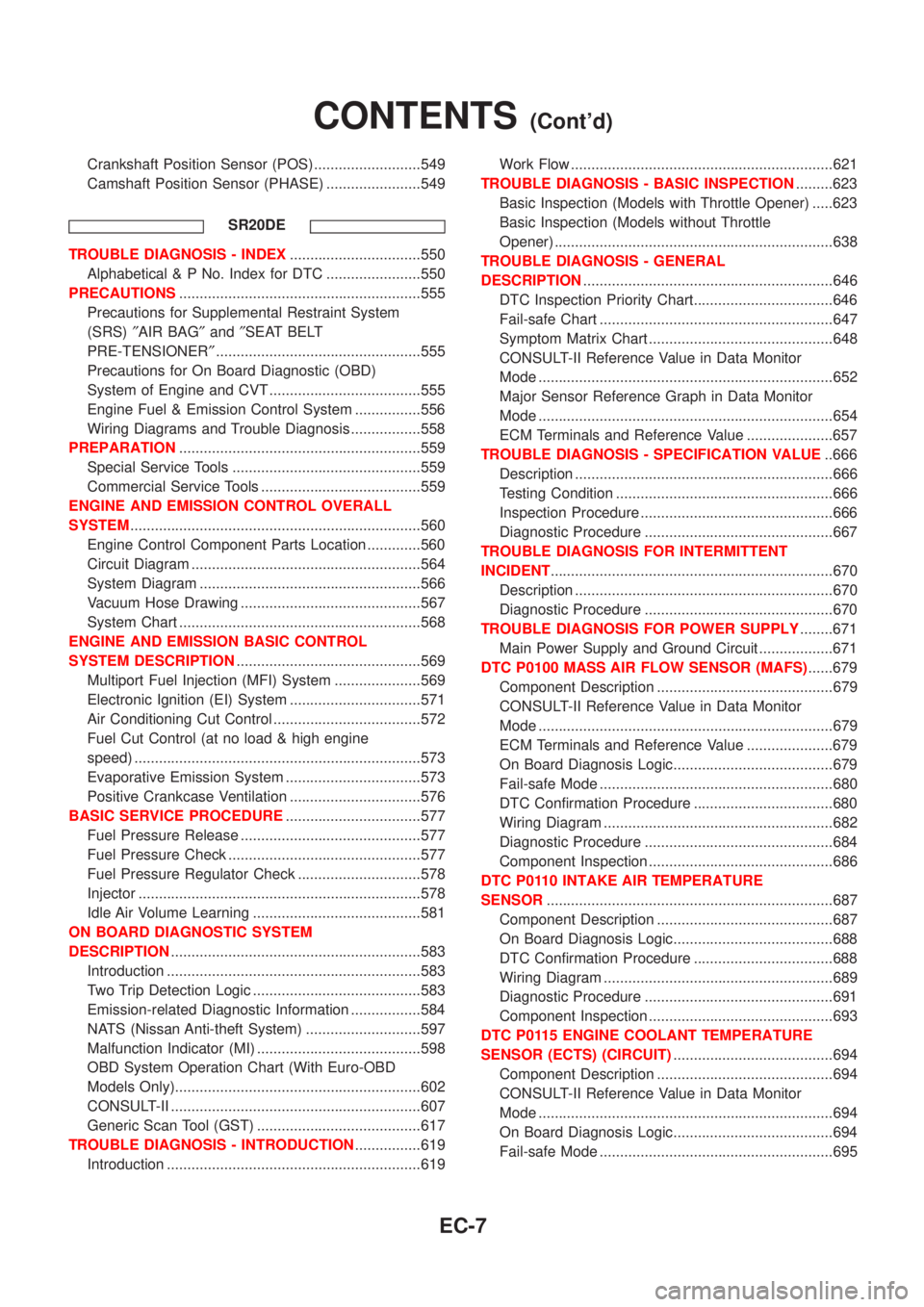
Crankshaft Position Sensor (POS) ..........................549
Camshaft Position Sensor (PHASE) .......................549
SR20DE
TROUBLE DIAGNOSIS - INDEX................................550
Alphabetical & P No. Index for DTC .......................550
PRECAUTIONS...........................................................555
Precautions for Supplemental Restraint System
(SRS)²AIR BAG²and²SEAT BELT
PRE-TENSIONER²..................................................555
Precautions for On Board Diagnostic (OBD)
System of Engine and CVT .....................................555
Engine Fuel & Emission Control System ................556
Wiring Diagrams and Trouble Diagnosis .................558
PREPARATION...........................................................559
Special Service Tools ..............................................559
Commercial Service Tools .......................................559
ENGINE AND EMISSION CONTROL OVERALL
SYSTEM.......................................................................560
Engine Control Component Parts Location .............560
Circuit Diagram ........................................................564
System Diagram ......................................................566
Vacuum Hose Drawing ............................................567
System Chart ...........................................................568
ENGINE AND EMISSION BASIC CONTROL
SYSTEM DESCRIPTION.............................................569
Multiport Fuel Injection (MFI) System .....................569
Electronic Ignition (EI) System ................................571
Air Conditioning Cut Control ....................................572
Fuel Cut Control (at no load & high engine
speed) ......................................................................573
Evaporative Emission System .................................573
Positive Crankcase Ventilation ................................576
BASIC SERVICE PROCEDURE.................................577
Fuel Pressure Release ............................................577
Fuel Pressure Check ...............................................577
Fuel Pressure Regulator Check ..............................578
Injector .....................................................................578
Idle Air Volume Learning .........................................581
ON BOARD DIAGNOSTIC SYSTEM
DESCRIPTION.............................................................583
Introduction ..............................................................583
Two Trip Detection Logic .........................................583
Emission-related Diagnostic Information .................584
NATS (Nissan Anti-theft System) ............................597
Malfunction Indicator (MI) ........................................598
OBD System Operation Chart (With Euro-OBD
Models Only)............................................................602
CONSULT-II .............................................................607
Generic Scan Tool (GST) ........................................617
TROUBLE DIAGNOSIS - INTRODUCTION................619
Introduction ..............................................................619Work Flow ................................................................621
TROUBLE DIAGNOSIS - BASIC INSPECTION.........623
Basic Inspection (Models with Throttle Opener) .....623
Basic Inspection (Models without Throttle
Opener) ....................................................................638
TROUBLE DIAGNOSIS - GENERAL
DESCRIPTION.............................................................646
DTC Inspection Priority Chart..................................646
Fail-safe Chart .........................................................647
Symptom Matrix Chart .............................................648
CONSULT-II Reference Value in Data Monitor
Mode ........................................................................652
Major Sensor Reference Graph in Data Monitor
Mode ........................................................................654
ECM Terminals and Reference Value .....................657
TROUBLE DIAGNOSIS - SPECIFICATION VALUE..666
Description ...............................................................666
Testing Condition .....................................................666
Inspection Procedure ...............................................666
Diagnostic Procedure ..............................................667
TROUBLE DIAGNOSIS FOR INTERMITTENT
INCIDENT.....................................................................670
Description ...............................................................670
Diagnostic Procedure ..............................................670
TROUBLE DIAGNOSIS FOR POWER SUPPLY........671
Main Power Supply and Ground Circuit ..................671
DTC P0100 MASS AIR FLOW SENSOR (MAFS)......679
Component Description ...........................................679
CONSULT-II Reference Value in Data Monitor
Mode ........................................................................679
ECM Terminals and Reference Value .....................679
On Board Diagnosis Logic.......................................679
Fail-safe Mode .........................................................680
DTC Confirmation Procedure ..................................680
Wiring Diagram ........................................................682
Diagnostic Procedure ..............................................684
Component Inspection .............................................686
DTC P0110 INTAKE AIR TEMPERATURE
SENSOR......................................................................687
Component Description ...........................................687
On Board Diagnosis Logic.......................................688
DTC Confirmation Procedure ..................................688
Wiring Diagram ........................................................689
Diagnostic Procedure ..............................................691
Component Inspection .............................................693
DTC P0115 ENGINE COOLANT TEMPERATURE
SENSOR (ECTS) (CIRCUIT).......................................694
Component Description ...........................................694
CONSULT-II Reference Value in Data Monitor
Mode ........................................................................694
On Board Diagnosis Logic.......................................694
Fail-safe Mode .........................................................695
CONTENTS(Cont'd)
EC-7