fuel tank removal NISSAN ALMERA TINO 2001 Service Repair Manual
[x] Cancel search | Manufacturer: NISSAN, Model Year: 2001, Model line: ALMERA TINO, Model: NISSAN ALMERA TINO 2001Pages: 3051, PDF Size: 46.38 MB
Page 1513 of 3051
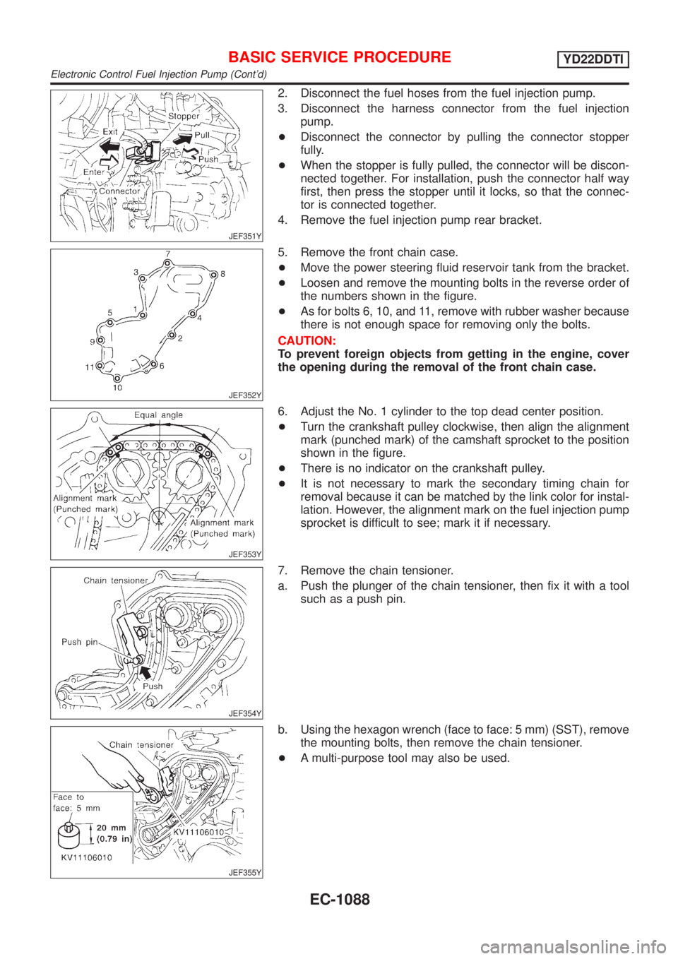
JEF351Y
2. Disconnect the fuel hoses from the fuel injection pump.
3. Disconnect the harness connector from the fuel injection
pump.
+Disconnect the connector by pulling the connector stopper
fully.
+When the stopper is fully pulled, the connector will be discon-
nected together. For installation, push the connector half way
first, then press the stopper until it locks, so that the connec-
tor is connected together.
4. Remove the fuel injection pump rear bracket.
JEF352Y
5. Remove the front chain case.
+Move the power steering fluid reservoir tank from the bracket.
+Loosen and remove the mounting bolts in the reverse order of
the numbers shown in the figure.
+As for bolts 6, 10, and 11, remove with rubber washer because
there is not enough space for removing only the bolts.
CAUTION:
To prevent foreign objects from getting in the engine, cover
the opening during the removal of the front chain case.
JEF353Y
6. Adjust the No. 1 cylinder to the top dead center position.
+Turn the crankshaft pulley clockwise, then align the alignment
mark (punched mark) of the camshaft sprocket to the position
shown in the figure.
+There is no indicator on the crankshaft pulley.
+It is not necessary to mark the secondary timing chain for
removal because it can be matched by the link color for instal-
lation. However, the alignment mark on the fuel injection pump
sprocket is difficult to see; mark it if necessary.
JEF354Y
7. Remove the chain tensioner.
a. Push the plunger of the chain tensioner, then fix it with a tool
such as a push pin.
JEF355Y
b. Using the hexagon wrench (face to face: 5 mm) (SST), remove
the mounting bolts, then remove the chain tensioner.
+A multi-purpose tool may also be used.
BASIC SERVICE PROCEDUREYD22DDTI
Electronic Control Fuel Injection Pump (Cont'd)
EC-1088
Page 2280 of 3051
CAUTION:
+After removing timing chain, do not turn crankshaft and
camshaft separately, or valves will strike piston heads.
+When installing chain tensioner, oil seals, or other sliding
parts, lubricate contacting surfaces with new engine oil.
+Apply new engine oil to bolt threads and seat surfaces
when installing camshaft sprocket and crankshaft pulley.
+When removing oil pump assembly, remove camshaft
position sensor (PHASE), then remove timing chain from
engine.
+Be careful not to damage sensor edges.
SEM869F
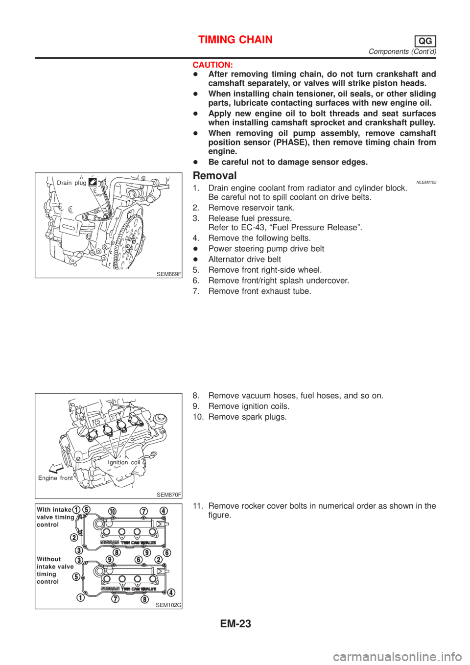
RemovalNLEM01051. Drain engine coolant from radiator and cylinder block.
Be careful not to spill coolant on drive belts.
2. Remove reservoir tank.
3. Release fuel pressure.
Refer to EC-43, ªFuel Pressure Releaseº.
4. Remove the following belts.
+Power steering pump drive belt
+Alternator drive belt
5. Remove front right-side wheel.
6. Remove front/right splash undercover.
7. Remove front exhaust tube.
SEM870F
8. Remove vacuum hoses, fuel hoses, and so on.
9. Remove ignition coils.
10. Remove spark plugs.
SEM102G
11. Remove rocker cover bolts in numerical order as shown in the
figure.
TIMING CHAINQG
Components (Cont'd)
EM-23
Page 2307 of 3051
WARNING:
+Position vehicle on a flat and solid surface.
+Place chocks at front and back of rear wheels.
+Do not remove engine until exhaust system has com-
pletely cooled off, otherwise, you may burn yourself
and/or fire may break out in fuel line.
+Before disconnecting fuel hose, release pressure.
Refer to EC-43, ªFuel Pressure Releaseº.
+Be sure to lift engine and transaxle in a safe manner.
+For engines not equipped with engine slingers, attach
proper slingers and bolts described in PARTS CATALOG.
CAUTION:
+When lifting engine, be sure to clear surrounding parts.
Use special care near accelerator wire casing, brake lines
and brake master cylinder.
+When lifting the engine, always use engine slingers in a
safe manner.
+When removing drive shaft, be careful not to damage
grease seal of transaxle.
+Before separating engine and transaxle, remove crank-
shaft position sensor (POS) from the cylinder block
assembly.
+Always be extra careful not to damage edge of crankshaft
position sensor (POS), or signal plate teeth.
Engine cannot be removed separately from transaxle. Remove
engine with transaxle as an assembly.
REMOVALNLEM0022S011. Drain coolant from radiator and cylinder block. Refer to LC-18,
ªChanging Engine Coolantº.
2. Remove coolant reservoir tank and bracket.
3. Drain engine oil.
4. Remove battery and battery tray.
5. Remove air cleaner and air duct.
6. Remove drive belts.
7. Remove alternator and air conditioner compressor from
engine.
8. Remove power steering oil pump from engine and position
aside.
Power steering oil pump does not need to be disconnected
from power steering tubes.
ENGINE ASSEMBLYQG
Removal and Installation (Cont'd)
EM-50
Page 2388 of 3051
crankshaft position sensor (OBD) from the assembly.
+Always be extra careful not to damage edge of crankshaft
position sensor (OBD) or ring gear teeth.
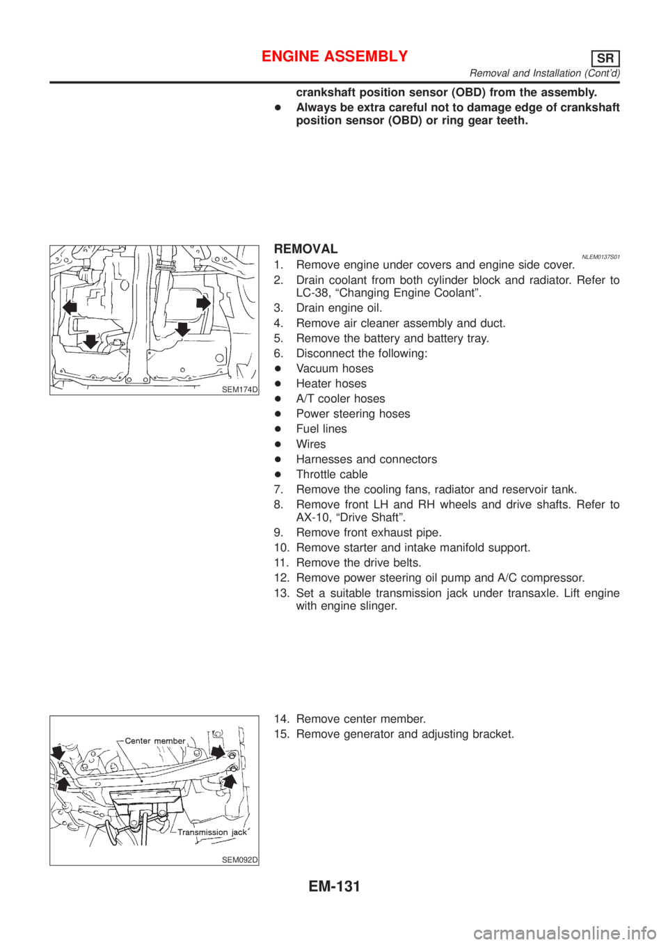
SEM174D
REMOVALNLEM0137S011. Remove engine under covers and engine side cover.
2. Drain coolant from both cylinder block and radiator. Refer to
LC-38, ªChanging Engine Coolantº.
3. Drain engine oil.
4. Remove air cleaner assembly and duct.
5. Remove the battery and battery tray.
6. Disconnect the following:
+Vacuum hoses
+Heater hoses
+A/T cooler hoses
+Power steering hoses
+Fuel lines
+Wires
+Harnesses and connectors
+Throttle cable
7. Remove the cooling fans, radiator and reservoir tank.
8. Remove front LH and RH wheels and drive shafts. Refer to
AX-10, ªDrive Shaftº.
9. Remove front exhaust pipe.
10. Remove starter and intake manifold support.
11. Remove the drive belts.
12. Remove power steering oil pump and A/C compressor.
13. Set a suitable transmission jack under transaxle. Lift engine
with engine slinger.
SEM092D
14. Remove center member.
15. Remove generator and adjusting bracket.
ENGINE ASSEMBLYSR
Removal and Installation (Cont'd)
EM-131
Page 2433 of 3051
JEM121G
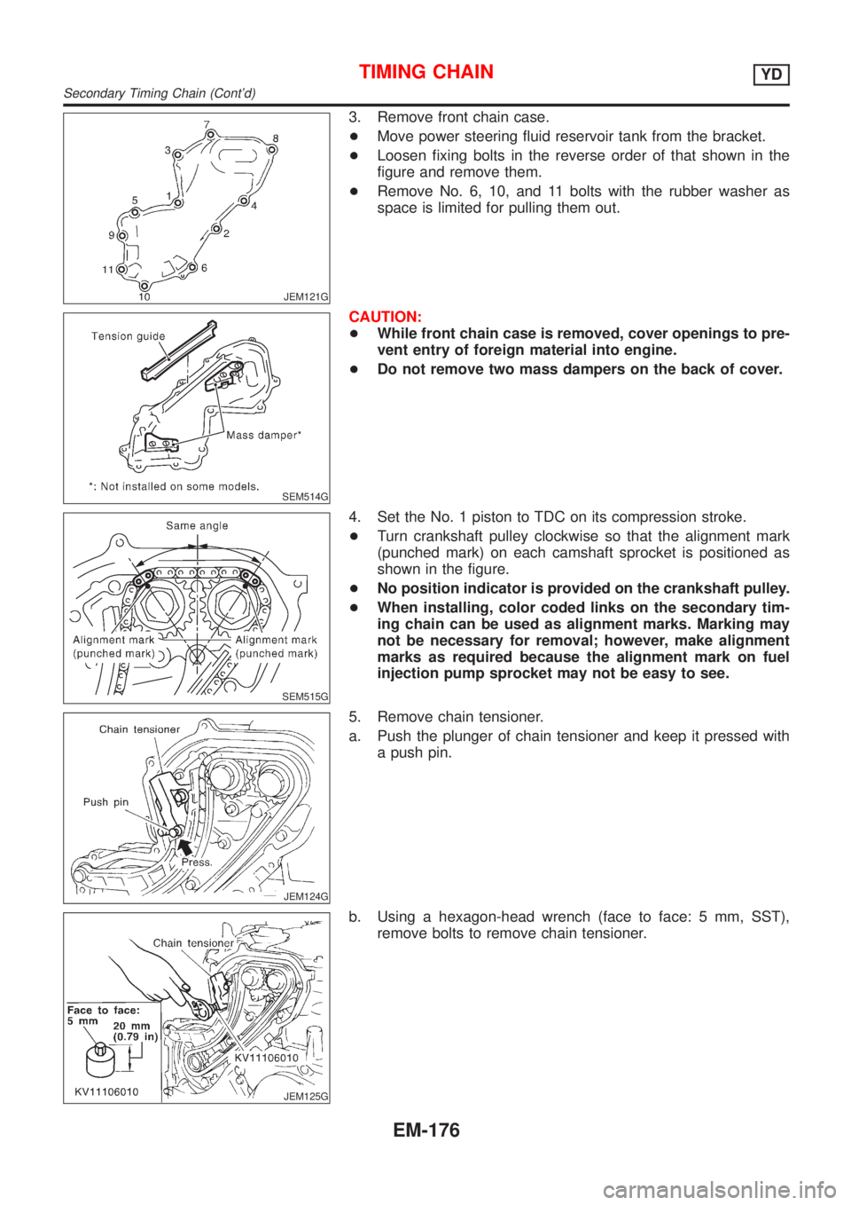
3. Remove front chain case.
+Move power steering fluid reservoir tank from the bracket.
+Loosen fixing bolts in the reverse order of that shown in the
figure and remove them.
+Remove No. 6, 10, and 11 bolts with the rubber washer as
space is limited for pulling them out.
SEM514G
CAUTION:
+While front chain case is removed, cover openings to pre-
vent entry of foreign material into engine.
+Do not remove two mass dampers on the back of cover.
SEM515G
4. Set the No. 1 piston to TDC on its compression stroke.
+Turn crankshaft pulley clockwise so that the alignment mark
(punched mark) on each camshaft sprocket is positioned as
shown in the figure.
+No position indicator is provided on the crankshaft pulley.
+When installing, color coded links on the secondary tim-
ing chain can be used as alignment marks. Marking may
not be necessary for removal; however, make alignment
marks as required because the alignment mark on fuel
injection pump sprocket may not be easy to see.
JEM124G
5. Remove chain tensioner.
a. Push the plunger of chain tensioner and keep it pressed with
a push pin.
JEM125G
b. Using a hexagon-head wrench (face to face: 5 mm, SST),
remove bolts to remove chain tensioner.
TIMING CHAINYD
Secondary Timing Chain (Cont'd)
EM-176
Page 2510 of 3051
ACCELERATOR CONTROL, FUEL &
EXHAUST SYSTEMS
SECTION
FE
CONTENTS
QG/SR
PREPARATION...............................................................2
Special Service Tools ..................................................2
Commercial Service Tools ...........................................2
ACCELERATOR CONTROL SYSTEM...........................3
Removal and Installation .............................................3
Adjusting Accelerator Wire ..........................................3
MODELS WITH THROTTLE OPENER.........................3
MODELS WITHOUT THROTTLE OPENER..................4
FUEL SYSTEM................................................................5
Checking Fuel Lines ....................................................5
Removal and Installation .............................................5
Fuel Tank .....................................................................6
REMOVAL.................................................................6
INSTALLATION..........................................................8
Fuel Pump, Fuel Level Sensor Unit and Fuel
Filter .............................................................................9
REMOVAL.................................................................9
INSTALLATION........................................................10
EXHAUST SYSTEM...................................................... 11
Checking Exhaust System......................................... 11
Removal and Installation ........................................... 11
YD
PREPARATION.............................................................13
Special Service Tool ..................................................13Commercial Service Tool ...........................................13
ACCELERATOR CONTROL SYSTEM.........................14
Removal and Installation ...........................................14
Inspection...................................................................14
FUEL SYSTEM..............................................................15
Checking Fuel Lines ..................................................15
Water Draining from Fuel Filter .................................15
DRAINING WATER..................................................15
FUEL FILTER CHECK..............................................15
Changing Fuel Filter ..................................................15
REMOVAL...............................................................15
INSTALLATION........................................................16
Bleeding Fuel Filter....................................................16
Checking Priming Pump ............................................16
Checking Water in Fuel Filter Sensor (where
fitted) ..........................................................................17
Removal and Installation ...........................................17
Fuel Tank ...................................................................18
REMOVAL...............................................................19
INSTALLATION........................................................20
Fuel Level Sensor Unit ..............................................21
REMOVAL...............................................................21
INSTALLATION........................................................22
EXHAUST SYSTEM......................................................23
Checking Exhaust System.........................................23
Removal and Installation ...........................................23
Page 2515 of 3051
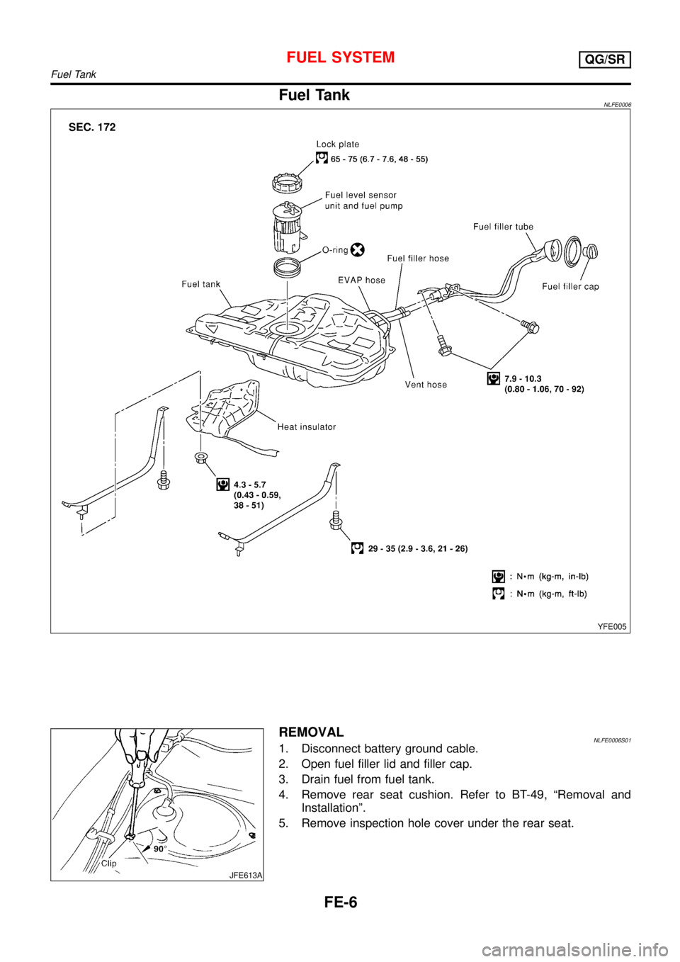
Fuel TankNLFE0006
YFE005
JFE613A
REMOVALNLFE0006S011. Disconnect battery ground cable.
2. Open fuel filler lid and filler cap.
3. Drain fuel from fuel tank.
4. Remove rear seat cushion. Refer to BT-49,“Removal and
Installation”.
5. Remove inspection hole cover under the rear seat.
FUEL SYSTEMQG/SR
Fuel Tank
FE-6
Page 2516 of 3051
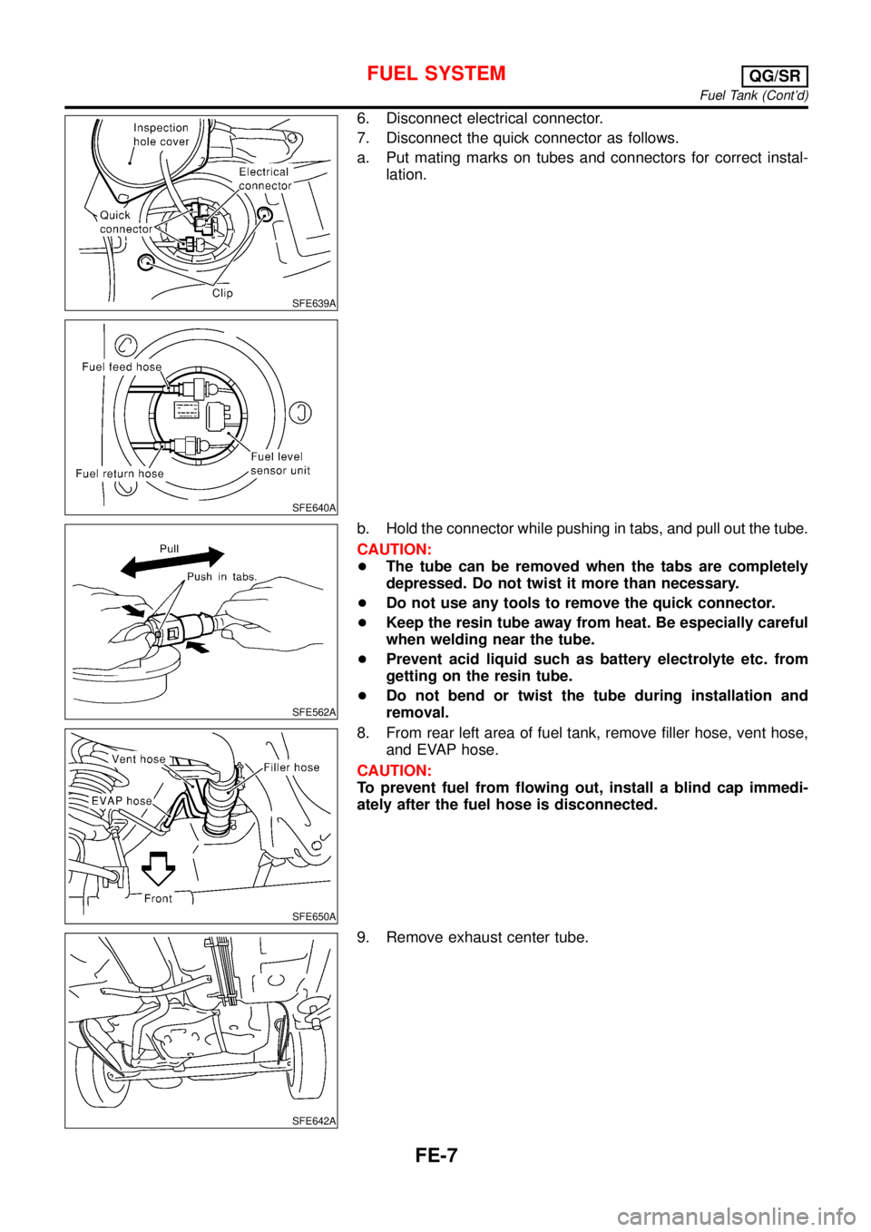
SFE639A
SFE640A
6. Disconnect electrical connector.
7. Disconnect the quick connector as follows.
a. Put mating marks on tubes and connectors for correct instal-
lation.
SFE562A
b. Hold the connector while pushing in tabs, and pull out the tube.
CAUTION:
+The tube can be removed when the tabs are completely
depressed. Do not twist it more than necessary.
+Do not use any tools to remove the quick connector.
+Keep the resin tube away from heat. Be especially careful
when welding near the tube.
+Prevent acid liquid such as battery electrolyte etc. from
getting on the resin tube.
+Do not bend or twist the tube during installation and
removal.
SFE650A
8. From rear left area of fuel tank, remove filler hose, vent hose,
and EVAP hose.
CAUTION:
To prevent fuel from flowing out, install a blind cap immedi-
ately after the fuel hose is disconnected.
SFE642A
9. Remove exhaust center tube.
FUEL SYSTEMQG/SR
Fuel Tank (Cont’d)
FE-7
Page 2517 of 3051
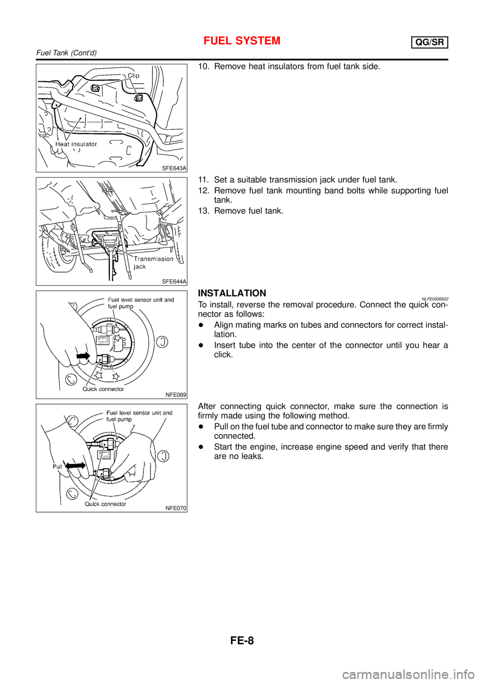
SFE643A
10. Remove heat insulators from fuel tank side.
SFE644A
11. Set a suitable transmission jack under fuel tank.
12. Remove fuel tank mounting band bolts while supporting fuel
tank.
13. Remove fuel tank.
NFE069
INSTALLATIONNLFE0006S02To install, reverse the removal procedure. Connect the quick con-
nector as follows:
+Align mating marks on tubes and connectors for correct instal-
lation.
+Insert tube into the center of the connector until you hear a
click.
NFE070
After connecting quick connector, make sure the connection is
firmly made using the following method.
+Pull on the fuel tube and connector to make sure they are firmly
connected.
+Start the engine, increase engine speed and verify that there
are no leaks.
FUEL SYSTEMQG/SR
Fuel Tank (Cont’d)
FE-8
Page 2518 of 3051
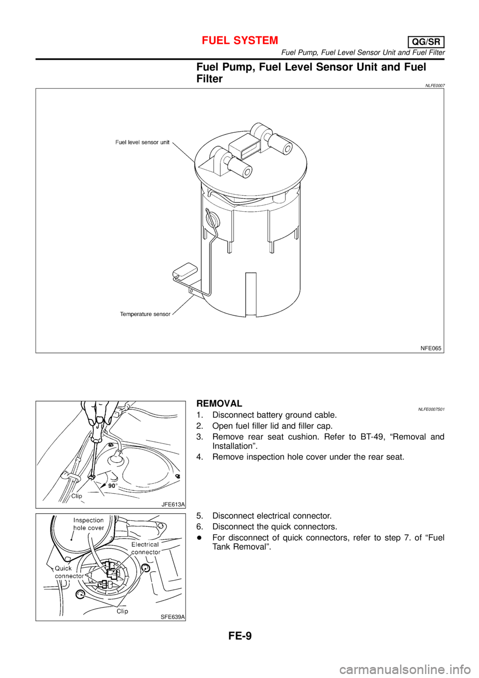
Fuel Pump, Fuel Level Sensor Unit and Fuel
Filter
NLFE0007
NFE065
JFE613A
REMOVALNLFE0007S011. Disconnect battery ground cable.
2. Open fuel filler lid and filler cap.
3. Remove rear seat cushion. Refer to BT-49,“Removal and
Installation”.
4. Remove inspection hole cover under the rear seat.
SFE639A
5. Disconnect electrical connector.
6. Disconnect the quick connectors.
+For disconnect of quick connectors, refer to step 7. of“Fuel
Tank Removal”.
FUEL SYSTEMQG/SR
Fuel Pump, Fuel Level Sensor Unit and Fuel Filter
FE-9