tank NISSAN ALMERA TINO 2001 Service Repair Manual
[x] Cancel search | Manufacturer: NISSAN, Model Year: 2001, Model line: ALMERA TINO, Model: NISSAN ALMERA TINO 2001Pages: 3051, PDF Size: 46.38 MB
Page 244 of 3051
NBR376
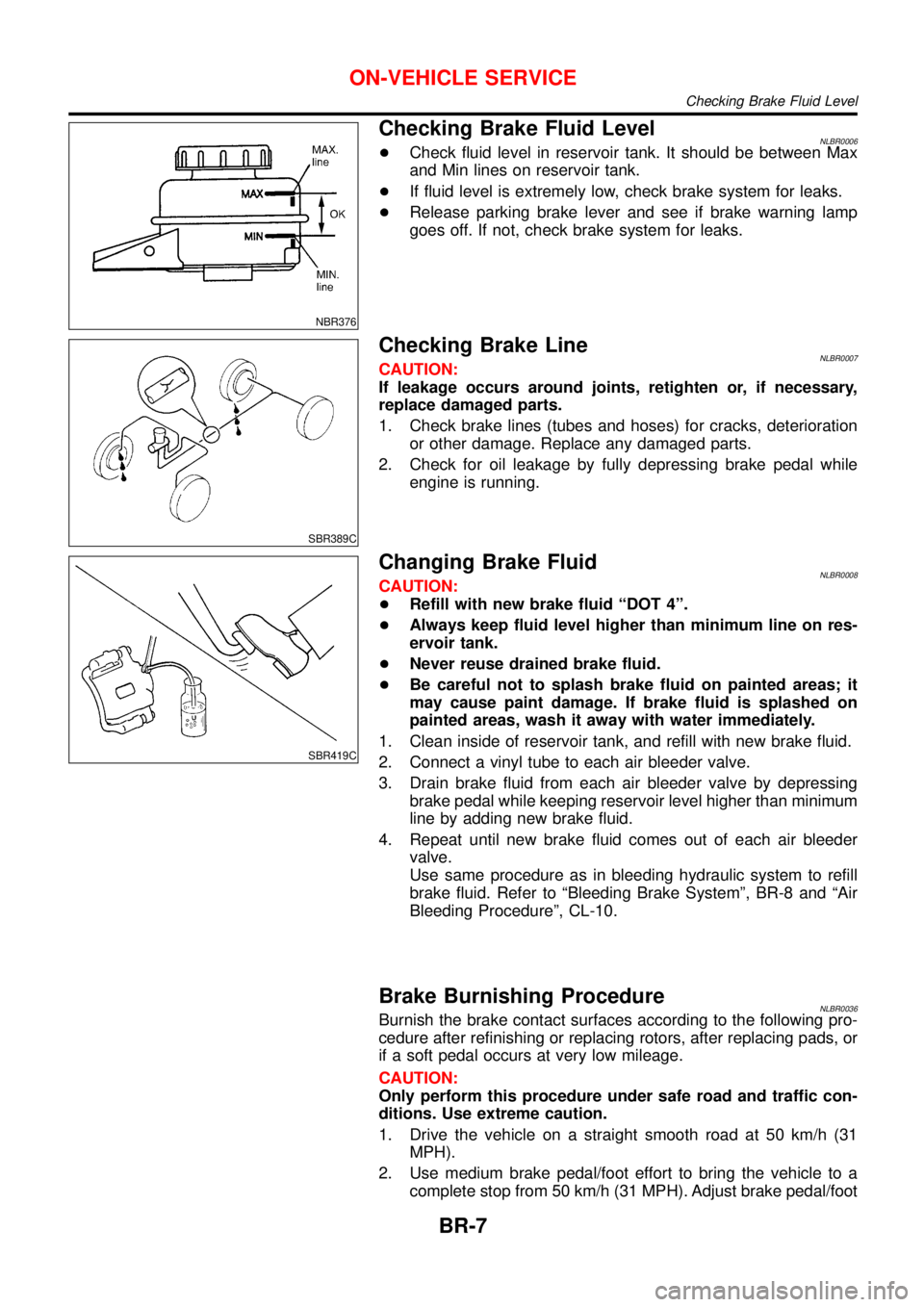
Checking Brake Fluid LevelNLBR0006+Check fluid level in reservoir tank. It should be between Max
and Min lines on reservoir tank.
+If fluid level is extremely low, check brake system for leaks.
+Release parking brake lever and see if brake warning lamp
goes off. If not, check brake system for leaks.
SBR389C
Checking Brake LineNLBR0007CAUTION:
If leakage occurs around joints, retighten or, if necessary,
replace damaged parts.
1. Check brake lines (tubes and hoses) for cracks, deterioration
or other damage. Replace any damaged parts.
2. Check for oil leakage by fully depressing brake pedal while
engine is running.
SBR419C
Changing Brake FluidNLBR0008CAUTION:
+Refill with new brake fluid“DOT 4”.
+Always keep fluid level higher than minimum line on res-
ervoir tank.
+Never reuse drained brake fluid.
+Be careful not to splash brake fluid on painted areas; it
may cause paint damage. If brake fluid is splashed on
painted areas, wash it away with water immediately.
1. Clean inside of reservoir tank, and refill with new brake fluid.
2. Connect a vinyl tube to each air bleeder valve.
3. Drain brake fluid from each air bleeder valve by depressing
brake pedal while keeping reservoir level higher than minimum
line by adding new brake fluid.
4. Repeat until new brake fluid comes out of each air bleeder
valve.
Use same procedure as in bleeding hydraulic system to refill
brake fluid. Refer to“Bleeding Brake System”, BR-8 and“Air
Bleeding Procedure”, CL-10.
Brake Burnishing ProcedureNLBR0036Burnish the brake contact surfaces according to the following pro-
cedure after refinishing or replacing rotors, after replacing pads, or
if a soft pedal occurs at very low mileage.
CAUTION:
Only perform this procedure under safe road and traffic con-
ditions. Use extreme caution.
1. Drive the vehicle on a straight smooth road at 50 km/h (31
MPH).
2. Use medium brake pedal/foot effort to bring the vehicle to a
complete stop from 50 km/h (31 MPH). Adjust brake pedal/foot
ON-VEHICLE SERVICE
Checking Brake Fluid Level
BR-7
Page 250 of 3051

RemovalNLBR0117
NBR360
1. Reservoir cap
2. Filter
3. Reservoir tank
4. Adapter5. Elastic pin
6. Seal
7. Washer
8. Circlip9. Piston stopper pin
10. Primary piston assembly
11. Secondary piston assembly
12. Cylinder body
CAUTION:
Be careful not to splash brake fluid on painted areas; it may
cause paint damage. If brake fluid is splashed on painted
areas, wash it away with water immediately.
1. Connect a vinyl tube to air bleeder valve.
2. Drain brake fluid from each front caliper air bleeder valve,
depressing brake pedal to empty fluid from master cylinder.
3. Remove brake pipe flare nuts.
4. Disconnect hoses from adapter.
5. Remove master cylinder mounting nuts.
NBR361
DisassemblyNLBR01181. Drive out elastic pin from cylinder body.
2. Remove adapter, washer and seals.
MASTER CYLINDER
Removal
BR-13
Page 252 of 3051
InstallationNLBR0121CAUTION:
+Refill with new brake fluid“DOT 4”.
+Never reuse drained brake fluid.
1. Place master cylinder onto brake booster and secure mount-
ing nuts lightly.
2. Torque mounting nuts.
:13-15N·m (1.3 - 1.5 kg-m,9-11ft-lb)
NBR363
NBR364
3. Check hoses for damage. If the hoses show cracks or damage,
replace the hose.
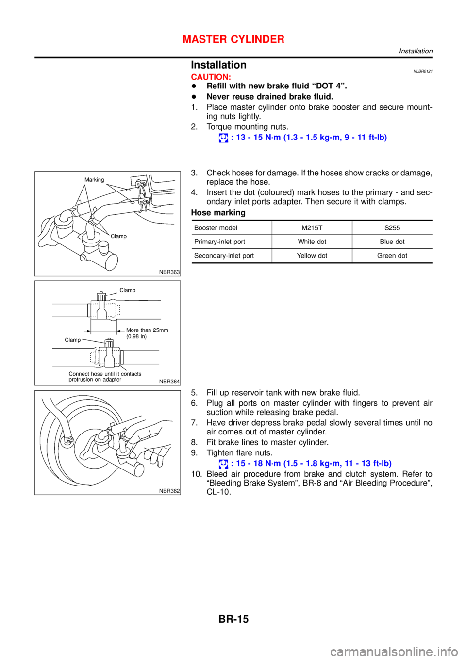
4. Insert the dot (coloured) mark hoses to the primary - and sec-
ondary inlet ports adapter. Then secure it with clamps.
Hose marking
Booster model M215T S255
Primary-inlet port White dot Blue dot
Secondary-inlet port Yellow dot Green dot
NBR362
5. Fill up reservoir tank with new brake fluid.
6. Plug all ports on master cylinder with fingers to prevent air
suction while releasing brake pedal.
7. Have driver depress brake pedal slowly several times until no
air comes out of master cylinder.
8. Fit brake lines to master cylinder.
9. Tighten flare nuts.
:15-18N·m (1.5 - 1.8 kg-m, 11 - 13 ft-lb)
10. Bleed air procedure from brake and clutch system. Refer to
“Bleeding Brake System”, BR-8 and“Air Bleeding Procedure”,
CL-10.
MASTER CYLINDER
Installation
BR-15
Page 302 of 3051

Preliminary CheckNLBR0095
1 CHECK BRAKE FLUID LEVEL
Check brake fluid level in reservoir tank.
Low fluid level may indicate brake pad wear or leakage from brake line.
NBR376
Is brake fluid filled between MAX and MIN lines on reservoir tank and/or has brake fluid been contaminated?
Ye s©GO TO 2.
No©Repair. GO TO 2.
2 CHECK BRAKE LINE
Check brake line for leakage.
SBR389C
Is leakage present at or around brake lines, tubes or hoses or are any of these parts cracked or damaged?
Ye s©GO TO 3.
No©Repair. GO TO 3.
TROUBLE DIAGNOSIS—BASIC INSPECTIONABS
Preliminary Check
BR-65
Page 304 of 3051

5 RECHECK BRAKE FLUID LEVEL
Check brake fluid level in reservoir tank again.
NBR376
Is brake fluid filled between MAX and MIN lines on reservoir tank and/or has brake fluid been contaminated?
Ye s©GO TO 6.
No©Fill up brake fluid.
6 CHECK WARNING LAMP ACTIVATION
Check warning lamp activation.
SBR759E
Does warning lamp turn on when ignition switch is turned“ON”?
Ye s©GO TO 7.
No©Check fuse, warning lamp bulb and warning lamp circuit.
7 CHECK WARNING LAMP DEACTIVATION
Check warning lamp for deactivation after engine is started.
Does warning lamp turn off when engine is started?
Ye s©GO TO 8.
No©Go to Self-diagnosis. Refer to BR-56, 58.
8 DRIVE VEHICLE
Drive vehicle at speeds over 30 km/h (19 MPH) for at least one minute.
Does warning lamp remain off after vehicle has been driven at 30 km/h (19 MPH) for at least one minute?
Ye s©END
No©Go to Self-diagnosis. Refer to BR-56, 58.
TROUBLE DIAGNOSIS—BASIC INSPECTIONABS
Preliminary Check (Cont’d)
BR-67
Page 406 of 3051
Components Ð RHD Model with QG Engine ÐNLCL0041
NCL046
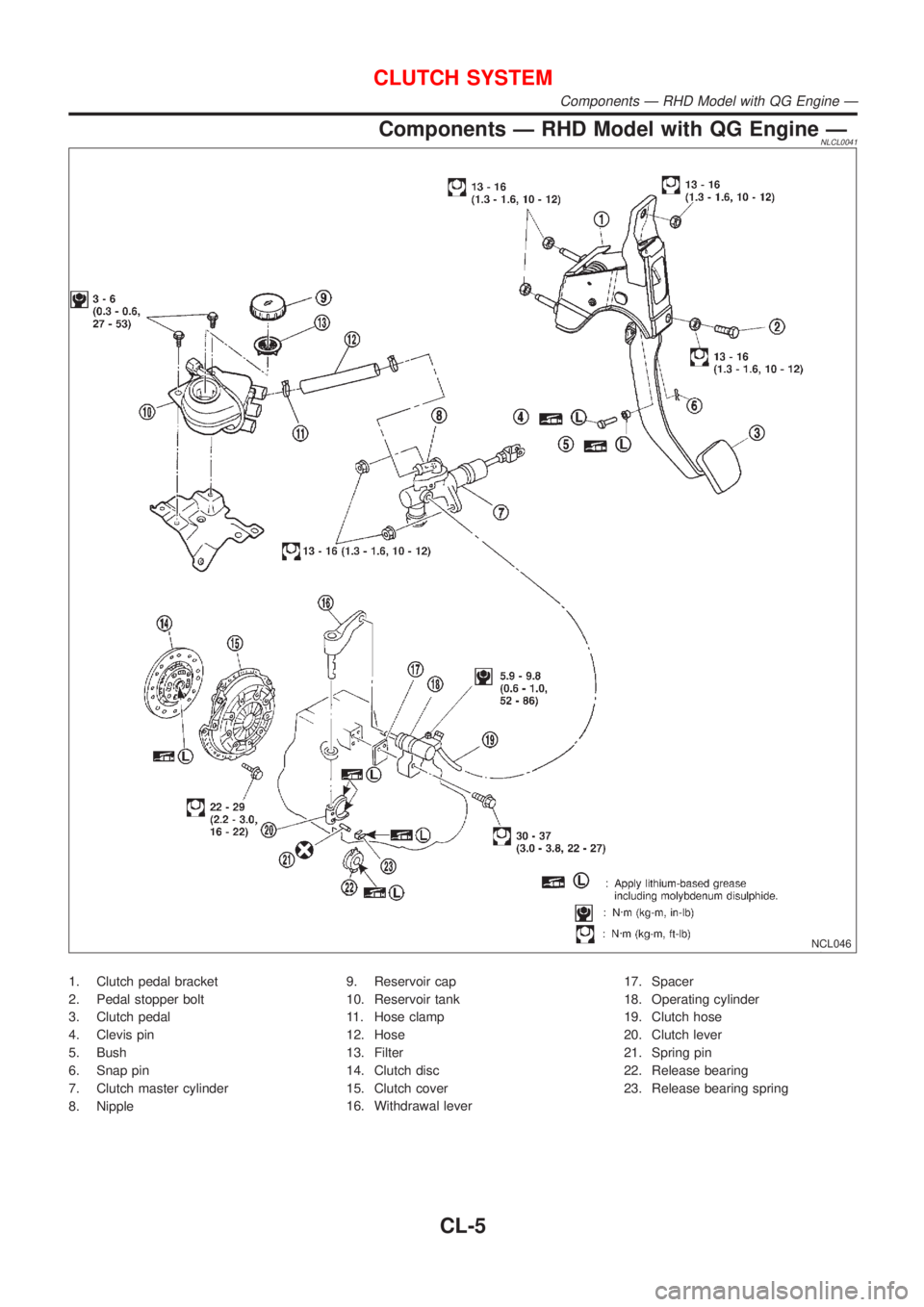
1. Clutch pedal bracket
2. Pedal stopper bolt
3. Clutch pedal
4. Clevis pin
5. Bush
6. Snap pin
7. Clutch master cylinder
8. Nipple9. Reservoir cap
10. Reservoir tank
11. Hose clamp
12. Hose
13. Filter
14. Clutch disc
15. Clutch cover
16. Withdrawal lever17. Spacer
18. Operating cylinder
19. Clutch hose
20. Clutch lever
21. Spring pin
22. Release bearing
23. Release bearing spring
CLUTCH SYSTEM
Components Ð RHD Model with QG Engine Ð
CL-5
Page 407 of 3051
Components Ð LHD Model with QG Engine ÐNLCL0048
NCL047
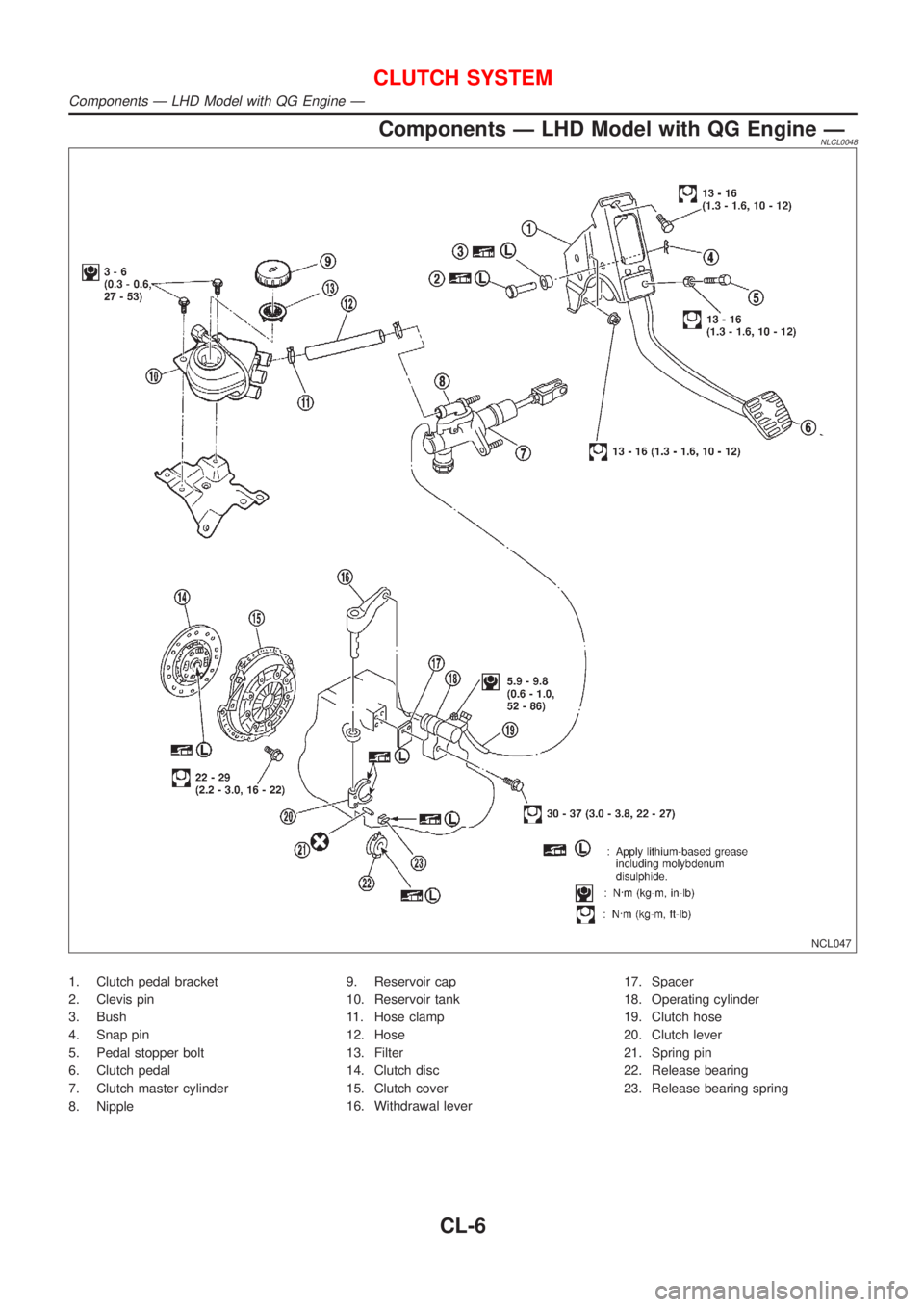
1. Clutch pedal bracket
2. Clevis pin
3. Bush
4. Snap pin
5. Pedal stopper bolt
6. Clutch pedal
7. Clutch master cylinder
8. Nipple9. Reservoir cap
10. Reservoir tank
11. Hose clamp
12. Hose
13. Filter
14. Clutch disc
15. Clutch cover
16. Withdrawal lever17. Spacer
18. Operating cylinder
19. Clutch hose
20. Clutch lever
21. Spring pin
22. Release bearing
23. Release bearing spring
CLUTCH SYSTEM
Components Ð LHD Model with QG Engine Ð
CL-6
Page 408 of 3051
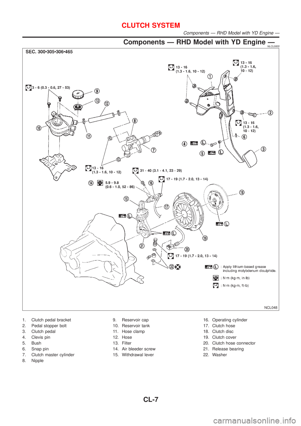
Components Ð RHD Model with YD Engine ÐNLCL0005
NCL048
1. Clutch pedal bracket
2. Pedal stopper bolt
3. Clutch pedal
4. Clevis pin
5. Bush
6. Snap pin
7. Clutch master cylinder
8. Nipple9. Reservoir cap
10. Reservoir tank
11. Hose clamp
12. Hose
13. Filter
14. Air bleeder screw
15. Withdrawal lever16. Operating cylinder
17. Clutch hose
18. Clutch disc
19. Clutch cover
20. Clutch hose connector
21. Release bearing
22. Washer
CLUTCH SYSTEM
Components Ð RHD Model with YD Engine Ð
CL-7
Page 409 of 3051
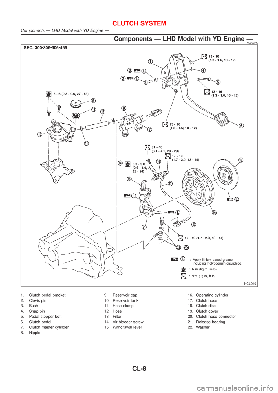
Components Ð LHD Model with YD Engine ÐNLCL0049
NCL049
1. Clutch pedal bracket
2. Clevis pin
3. Bush
4. Snap pin
5. Pedal stopper bolt
6. Clutch pedal
7. Clutch master cylinder
8. Nipple9. Reservoir cap
10. Reservoir tank
11. Hose clamp
12. Hose
13. Filter
14. Air bleeder screw
15. Withdrawal lever16. Operating cylinder
17. Clutch hose
18. Clutch disc
19. Clutch cover
20. Clutch hose connector
21. Release bearing
22. Washer
CLUTCH SYSTEM
Components Ð LHD Model with YD Engine Ð
CL-8
Page 450 of 3051
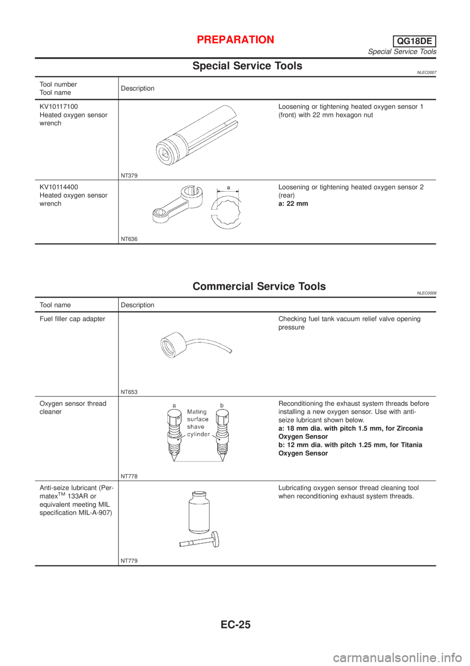
Special Service ToolsNLEC0007
Tool number
Tool nameDescription
KV10117100
Heated oxygen sensor
wrench
NT379
Loosening or tightening heated oxygen sensor 1
(front) with 22 mm hexagon nut
KV10114400
Heated oxygen sensor
wrench
NT636
Loosening or tightening heated oxygen sensor 2
(rear)
a: 22 mm
Commercial Service ToolsNLEC0008
Tool name Description
Fuel filler cap adapter
NT653
Checking fuel tank vacuum relief valve opening
pressure
Oxygen sensor thread
cleaner
NT778
Reconditioning the exhaust system threads before
installing a new oxygen sensor. Use with anti-
seize lubricant shown below.
a: 18 mm dia. with pitch 1.5 mm, for Zirconia
Oxygen Sensor
b: 12 mm dia. with pitch 1.25 mm, for Titania
Oxygen Sensor
Anti-seize lubricant (Per-
matex
TM133AR or
equivalent meeting MIL
specification MIL-A-907)
NT779
Lubricating oxygen sensor thread cleaning tool
when reconditioning exhaust system threads.
PREPARATIONQG18DE
Special Service Tools
EC-25