instrument panel NISSAN ALTIMA 1996 U13 / 1.G Owners Manual
[x] Cancel search | Manufacturer: NISSAN, Model Year: 1996, Model line: ALTIMA, Model: NISSAN ALTIMA 1996 U13 / 1.GPages: 183, PDF Size: 1.38 MB
Page 6 of 183

1 Instruments and controls
Meters and gauges .............................................. 1-2
Speedometer and odometer ................................ 1-3
Tachometer .......................................................... 1-3
Engine coolant temperature gauge and
Fuel gauge ........................................................... 1-4
Warning/indicator lights and chimes .................... 1-5
Theft warning (If so equipped) ............................. 1-8
Windshield wiper and washer switch ................... 1-9
Rear window defogger switch ............................ 1-10
Headlight and turn signal switch ........................ 1-11
Cornering light .................................................... 1-12Instrument brightness control ............................. 1-12
Front fog light switch (If so equipped) ............... 1-13
Hazard warning flasher switch ........................... 1-13
Cigarette lighter (accessory) and ashtray .......... 1-14
Cup holder .......................................................... 1-14
Power windows (If so equipped) ........................ 1-15
Sunroof (If so equipped) .................................... 1-17
Clock Ð instrument panel (If so equipped) ....... 1-18
Interior light......................................................... 1-18
Spotlight (If so equipped) ................................... 1-19
Trunk light........................................................... 1-19
ZX
Page 17 of 183

Turn signal
Move the lever up or down to signal the
turning direction. When the turn is com-
pleted, the turn signals cancel automati-
cally.
Lane change signal
To indicate a lane change, move the lever
up or down to the point where lights begin
flashing.
The cornering light provides additional illu-
mination toward the turning direction on
some models. The light on the turning direc-
tion side will come on when the turn signal
lever is moved to the right or left with the
headlights on.The instrument brightness control operates
when the light switch is in the ``
'' or
``'' position.
Turn the control to adjust the brightness of
instrument panel lights.
NOTE: For vehicles with the clock located in
the instrument panel (if so equipped) the
instrument brightness control function has
no effect on the brightness of the clock.
IC1030IC1269
CORNERING LIGHT INSTRUMENT BRIGHTNESS
CONTROL
1-12
ZX
Page 23 of 183
CAUTION
Turn the ignition key to the ``OFF''
position.
1. Remove the spotlight unit. The shaft end
of the sunroof motor will be visible.
2. Using a 5mm (0.20 in) hex wrench, turn
the shaft clockwise to close the sunroof.
Have the sunroof system checked and re-
paired by your NISSAN dealer.
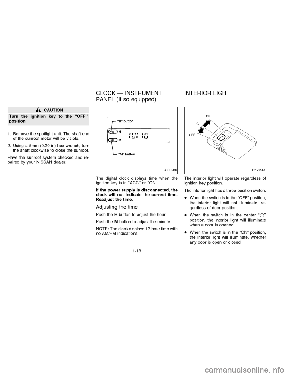
The digital clock displays time when the
ignition key is in ``ACC'' or ``ON''.
If the power supply is disconnected, the
clock will not indicate the correct time.
Readjust the time.
Adjusting the time
Push theHbutton to adjust the hour.
Push theMbutton to adjust the minute.
NOTE: The clock displays 12-hour time with
no AM/PM indications.The interior light will operate regardless of
ignition key position.
The interior light has a three-position switch.
cWhen the switch is in the ªOFFº position,
the interior light will not illuminate, re-
gardless of door position.
cWhen the switch is in the center ``j''
position, the interior light will illuminate
when a door is opened.
cWhen the switch is in the ªONº position,
the interior light will illuminate, whether
any door is open or closed.
AIC0500IC1235M
CLOCK Ð INSTRUMENT
PANEL (If so equipped)INTERIOR LIGHT
1-18
ZX
Page 30 of 183
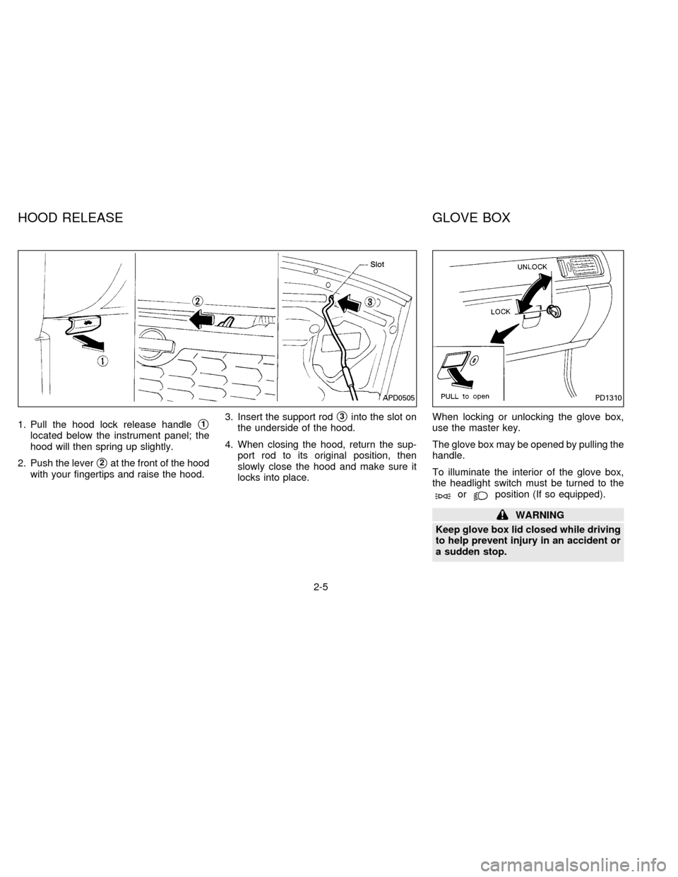
1. Pull the hood lock release handles1
located below the instrument panel; the
hood will then spring up slightly.
2. Push the lever
s2at the front of the hood
with your fingertips and raise the hood.3. Insert the support rod
s3into the slot on
the underside of the hood.
4. When closing the hood, return the sup-
port rod to its original position, then
slowly close the hood and make sure it
locks into place.When locking or unlocking the glove box,
use the master key.
The glove box may be opened by pulling the
handle.
To illuminate the interior of the glove box,
the headlight switch must be turned to the
orposition (If so equipped).
WARNING
Keep glove box lid closed while driving
to help prevent injury in an accident or
a sudden stop.
APD0505PD1310
HOOD RELEASE GLOVE BOX
2-5
ZX
Page 37 of 183
This Supplemental Restraint System sec-
tion contains important information concern-
ing the driver and passenger air bags. The
Supplemental Restraint System Air Bag can
help reduce impact force to the driver and to
the front passenger in certain frontal colli-
sions. The air bags are designed tosupple-
mentthe crash protection provided by the
driver and front passenger seat belts and
arenot a substitutefor them. The seat
belts should always be correctly worn and
the driver and front passenger seated a
suitable distance from the steering wheel
and instrument panel. (See ``Seat belts'' for
instructions and precautions on seat belt
usage.)
The supplemental air bags will operate
only when the ignition switch is in the
``ON'' or ``START'' position.
WARNING
The supplemental air bags ordinarily
will not inflate in the event of a side
impact, rear impact, roll over, or lower
severity frontal collision; so always
wear your seat belts to help reduce the
risk or severity of injury in various
kinds of accidents.
WARNING
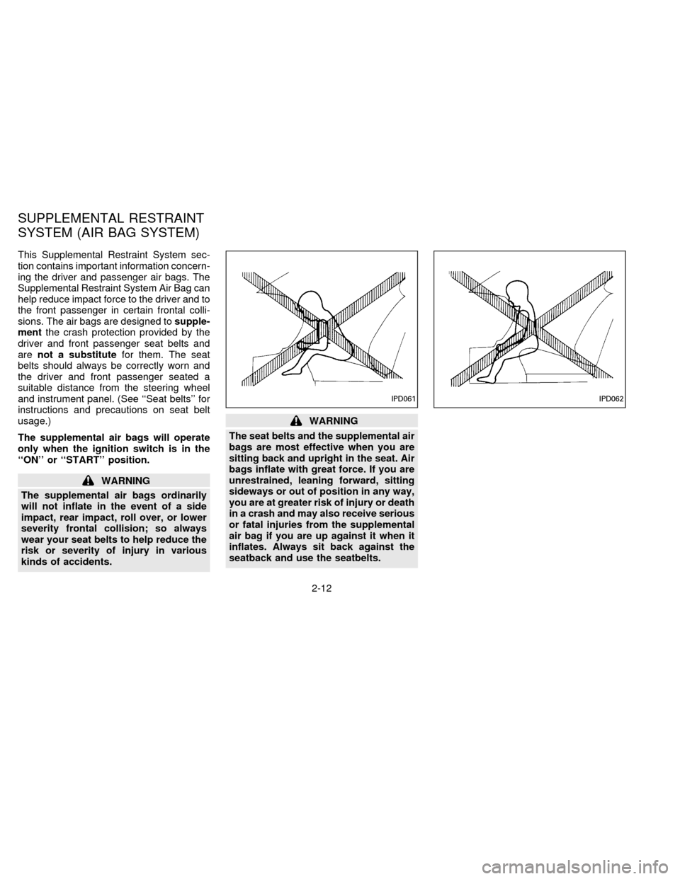
The seat belts and the supplemental air
bags are most effective when you are
sitting back and upright in the seat. Air
bags inflate with great force. If you are
unrestrained, leaning forward, sitting
sideways or out of position in any way,
you are at greater risk of injury or death
in a crash and may also receive serious
or fatal injuries from the supplemental
air bag if you are up against it when it
inflates. Always sit back against the
seatback and use the seatbelts.
IPD062IPD061
SUPPLEMENTAL RESTRAINT
SYSTEM (AIR BAG SYSTEM)
2-12
ZX
Page 40 of 183
changes to the steering wheel and
the instrument panel assembly by
placing material over the steering
wheel pad and above the dashboard,
or by installing additional trim mate-
rial around the supplemental air bag
system.
cDo not place any objects on the
steering wheel pad or on the instru-
ment panel. Also, do not place any
objects between any occupant and
the steering wheel or instrument
panel. Such objects may become
dangerous projectiles and cause in-
jury if the air bag inflates.
cWork around and on the supplemen-
tal air bag system should be done by
an authorized NISSAN dealer. Instal-
lation of electrical equipment should
also be done by an authorized NIS-
SAN dealer. The yellow SRS wiring
should not be modified or discon-
nected. Unauthorized electrical test
equipment and probing devices
should not be used on the supple-
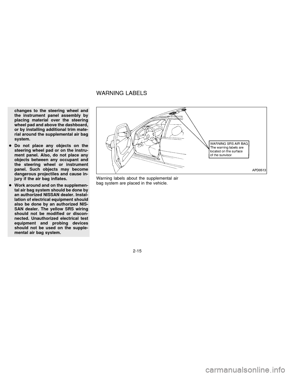
mental air bag system.Warning labels about the supplemental air
bag system are placed in the vehicle.
APD0513
WARNING LABELS
2-15
ZX
Page 41 of 183
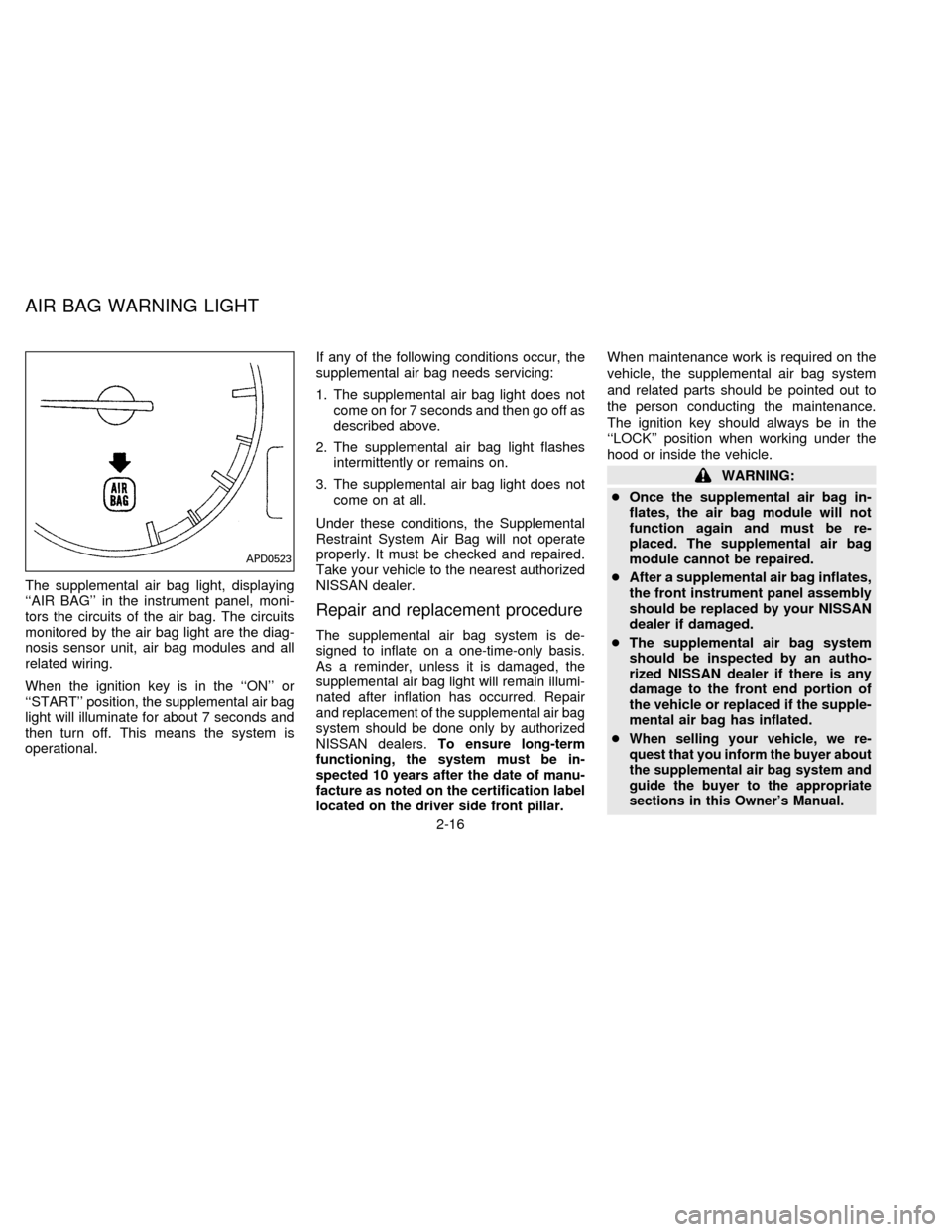
The supplemental air bag light, displaying
``AIR BAG'' in the instrument panel, moni-
tors the circuits of the air bag. The circuits
monitored by the air bag light are the diag-
nosis sensor unit, air bag modules and all
related wiring.
When the ignition key is in the ``ON'' or
``START'' position, the supplemental air bag
light will illuminate for about 7 seconds and
then turn off. This means the system is
operational.If any of the following conditions occur, the
supplemental air bag needs servicing:
1. The supplemental air bag light does not
come on for 7 seconds and then go off as
described above.
2. The supplemental air bag light flashes
intermittently or remains on.
3. The supplemental air bag light does not
come on at all.
Under these conditions, the Supplemental
Restraint System Air Bag will not operate
properly. It must be checked and repaired.
Take your vehicle to the nearest authorized
NISSAN dealer.
Repair and replacement procedure
The supplemental air bag system is de-
signed to inflate on a one-time-only basis.
As a reminder, unless it is damaged, the
supplemental air bag light will remain illumi-
nated after inflation has occurred. Repair
and replacement of the supplemental air bag
system should be done only by authorized
NISSAN dealers.To ensure long-term
functioning, the system must be in-
spected 10 years after the date of manu-
facture as noted on the certification label
located on the driver side front pillar.
When maintenance work is required on the
vehicle, the supplemental air bag system
and related parts should be pointed out to
the person conducting the maintenance.
The ignition key should always be in the
``LOCK'' position when working under the
hood or inside the vehicle.
WARNING:
cOnce the supplemental air bag in-
flates, the air bag module will not
function again and must be re-
placed. The supplemental air bag
module cannot be repaired.
cAfter a supplemental air bag inflates,
the front instrument panel assembly
should be replaced by your NISSAN
dealer if damaged.
cThe supplemental air bag system
should be inspected by an autho-
rized NISSAN dealer if there is any
damage to the front end portion of
the vehicle or replaced if the supple-
mental air bag has inflated.
c
When selling your vehicle, we re-
quest that you inform the buyer about
the supplemental air bag system and
guide the buyer to the appropriate
sections in this Owner's Manual.
APD0523
AIR BAG WARNING LIGHT
2-16
ZX
Page 54 of 183
A child restraint with a top strap should not
be used in the front passenger seat.
WARNING
cThe 3-point belt in your vehicle is
equipped with a locking mode re-
tractor which must be used when
installing a child restraint.
cFailure to use the retractor's locking
mode will result in the child restraint
not being properly secured. The seat
could tip over or otherwise be unse-
cured and cause injury to the child in
a sudden stop or collision.
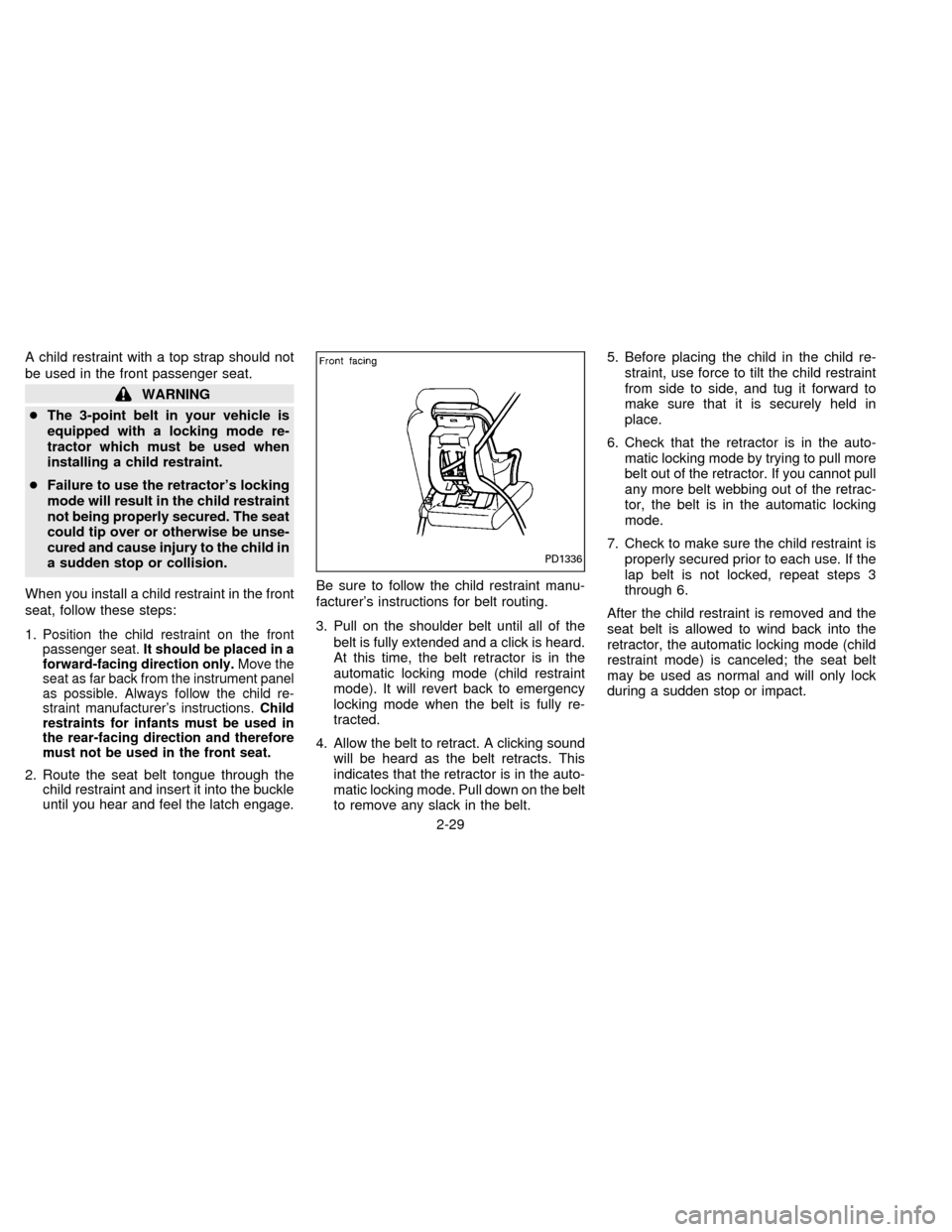
When you install a child restraint in the front
seat, follow these steps:
1.
Position the child restraint on the front
passenger seat.It should be placed in a
forward-facing direction only.Move the
seat as far back from the instrument panel
as possible. Always follow the child re-
straint manufacturer's instructions.Child
restraints for infants must be used in
the rear-facing direction and therefore
must not be used in the front seat.
2. Route the seat belt tongue through the
child restraint and insert it into the buckle
until you hear and feel the latch engage.Be sure to follow the child restraint manu-
facturer's instructions for belt routing.
3. Pull on the shoulder belt until all of the
belt is fully extended and a click is heard.
At this time, the belt retractor is in the
automatic locking mode (child restraint
mode). It will revert back to emergency
locking mode when the belt is fully re-
tracted.
4. Allow the belt to retract. A clicking sound
will be heard as the belt retracts. This
indicates that the retractor is in the auto-
matic locking mode. Pull down on the belt
to remove any slack in the belt.5. Before placing the child in the child re-
straint, use force to tilt the child restraint
from side to side, and tug it forward to
make sure that it is securely held in
place.
6. Check that the retractor is in the auto-
matic locking mode by trying to pull more
belt out of the retractor. If you cannot pull
any more belt webbing out of the retrac-
tor, the belt is in the automatic locking
mode.
7. Check to make sure the child restraint is
properly secured prior to each use. If the
lap belt is not locked, repeat steps 3
through 6.
After the child restraint is removed and the
seat belt is allowed to wind back into the
retractor, the automatic locking mode (child
restraint mode) is canceled; the seat belt
may be used as normal and will only lock
during a sudden stop or impact.
PD1336
2-29
ZX
Page 67 of 183

The sensor on the instrument panel helps
maintain a constant temperature; do not put
anything on or around this sensor.
Servicing air conditioning
The air conditioning system in your NISSAN
vehicle is charged with a new refrigerant
designed with the environment in mind.
This new refrigerant will not harm the
earth's ozone layer.
Special charging equipment and lubricant is
required when servicing your NISSAN air
conditioner. Using improper refrigerants or
lubricants will cause severe damage to your
air conditioning system. See ``Air condition-
ing system refrigerant and lubricant recom-
mendations'' in the ``Technical and con-
sumer information'' section of this manual.
Your NISSAN dealer will be able to service
your environmentally conscious air condi-
tioning system.To turn the radio on, turn the ignition key to
``ACC'' or ``ON''. If you listen to the radio with
the engine not running, turn the key to the
``ACC'' position.
Radio reception is affected by station signal
strength, distance from radio transmitter,
buildings, bridges, mountains and other ex-
ternal influences. Intermittent changes in
reception quality normally are caused by
these external influences.
CLOCK-RADIO (If so equipped)
On vehicles equipped with an AM-FM radio
and cassette player, a clock is integrated
into the audio system. For further details,
refer to Clock Operation later in this section.AHA0501
RADIO
3-10
ZX
Page 87 of 183

Overdrive switch
ON: For normal driving, push the over-
drive switch ON with the shift lever in
the ``D'' position. The transmission
will shift into OVERDRIVE as the
vehicle speed increases.
The overdrive will not engage until the
engine has warmed up.OFF: For driving up and down long slopes
where engine ``braking'' would be
advantageous, push the switch OFF.
When cruising at a low speed or
climbing a gentle slope, you may feel
uncomfortable shift shocks as the
transmission shifts between 3rd and
overdrive repeatedly. In this case,
set the overdrive switch in the OFF
position. The O/D OFF indicator light
on the instrument panel will come on
at this time.
When driving conditions change, reset the
overdrive switch to the ON position.
Remember not to drive at high speeds for
extended periods of time with the overdrive
switch set in the OFF position. This reduces
the fuel economy.
To change gears, fully depress the clutch
pedal, and then move the gearshift lever.
After shifting, release the clutch pedal slowly.
On the 5-speed transmission model, you
cannot shift directly from 5th gear into Re-
verse. First shift into Neutral, then into Re-
verse.
If it is difficult to move the gear shift lever
into Reverse or First, shift into Neutral, then
release and depress the clutch pedal again
and shift into Reverse or First.
Driving precautions
cDo not rest your foot on the clutch pedal
ASD0511SD1022
DRIVING WITH MANUAL
TRANSMISSION
4-8
ZX