turn signal NISSAN ALTIMA 2002 L31 / 3.G Owners Manual
[x] Cancel search | Manufacturer: NISSAN, Model Year: 2002, Model line: ALTIMA, Model: NISSAN ALTIMA 2002 L31 / 3.GPages: 249, PDF Size: 2.02 MB
Page 49 of 249

2 Instruments and controls
Instrument panel ....................................................2-2
Meters and gauges ................................................2-3
Speedometer and odometer .............................2-3
Trip computer ....................................................2-3
Tachometer........................................................2-6
Engine coolant temperature gauge ...................2-6
Fuel gauge ........................................................2-7
Warning/indicator lights and audible
reminders................................................................2-8
Checking bulbs ..................................................2-8
Warning lights ....................................................2-8
Indicator lights .................................................2-11
Audible reminders............................................2-12
Security systems ..................................................2-13
Nissan vehicle immobilizer system
(NVIS) ..............................................................2-13
Vehicle security system (if so equipped) ........2-14
Windshield wiper and washer switch ...................2-17
Switch operation ..............................................2-17
Rear window defogger switch ..............................2-17
Headlight and turn signal switch ..........................2-18
Xenon headlights .............................................2-18Headlight switch ..............................................2-19
Autolamp system (if so equipped)...................2-20
Turn signal switch............................................2-21
Fog light switch (if so equipped) ..........................2-21
Hazard warning flasher switch .............................2-23
Horn ......................................................................2-23
Heated seats (if so equipped) ..............................2-24
Traction control system (TCS) cancel switch
(if so equipped) ....................................................2-25
Power outlet .......................................................2-25
Storage .................................................................2-26
Seatback pockets (if so equipped) ..................2-26
Seatback side pockets (if so equipped) ..........2-26
Sunglasses case .............................................2-26
Cup holders .....................................................2-27
Glove box ........................................................2-28
Console box ....................................................2-28
Covered storage box .......................................2-29
Cargo net (if so equipped) ..............................2-30
Windows ...............................................................2-31
Power windows................................................2-31
Sunroof (if so equipped).......................................2-33
ZX
Page 51 of 249

1. Headlight and turn signal switch
2. Meters and gauges
3. Windshield wiper/washer switch
4. Center ventilator
5. Audio system
6. Front passenger supplemental air bag
7. Glove box
8. Heater and air conditioner
9. Hazard warning flasher switch
10. Power point
11. Rear window defogger switch
12. Cruise control main/set switch
13. Driver supplemental air bag
14. Steering wheel switch for audio control
15. Tilt/telescopic steering wheel lever
16. Traction control system (TLS) cancel
switch
17. Instrument brightness control
18. Outside mirror remote control
LIC0161
INSTRUMENT PANEL
2-2Instruments and controls
ZX
Page 57 of 249
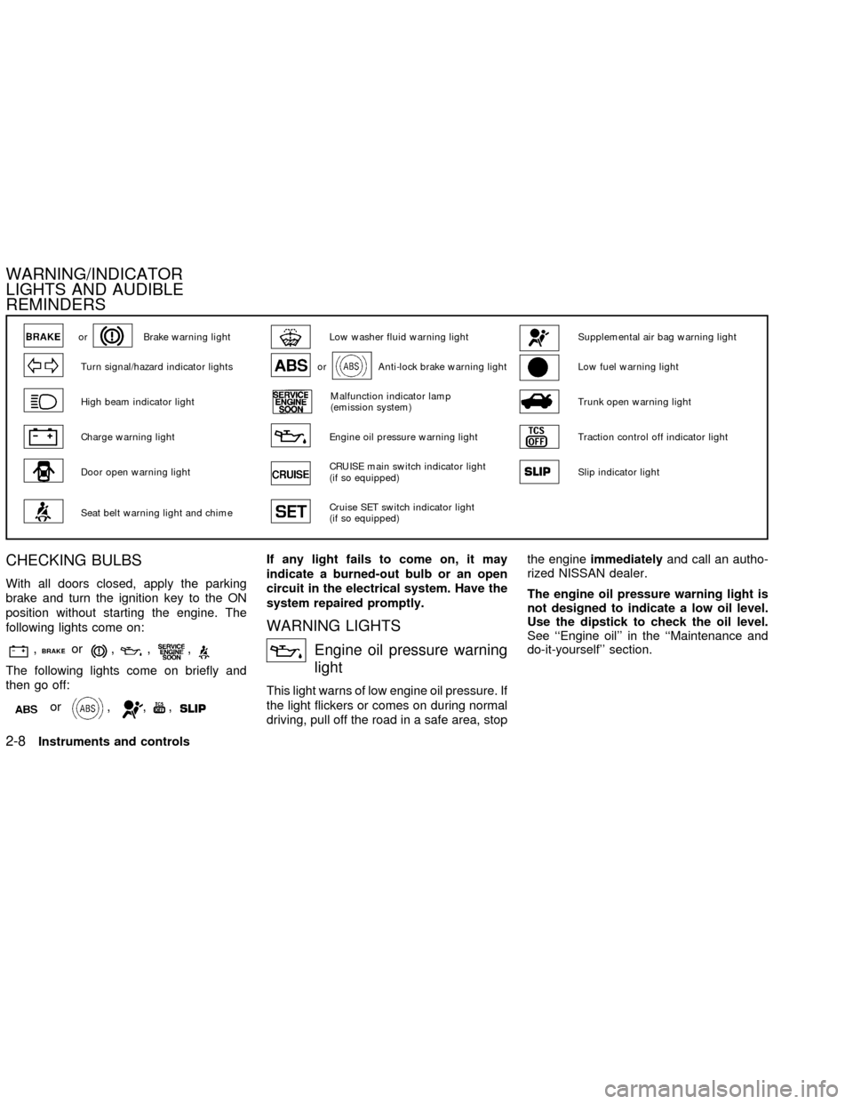
CHECKING BULBS
With all doors closed, apply the parking
brake and turn the ignition key to the ON
position without starting the engine. The
following lights come on:
,or,,,
The following lights come on briefly and
then go off:
or,,,
If any light fails to come on, it may
indicate a burned-out bulb or an open
circuit in the electrical system. Have the
system repaired promptly.
WARNING LIGHTS
Engine oil pressure warning
light
This light warns of low engine oil pressure. If
the light flickers or comes on during normal
driving, pull off the road in a safe area, stopthe engineimmediatelyand call an autho-
rized NISSAN dealer.
The engine oil pressure warning light is
not designed to indicate a low oil level.
Use the dipstick to check the oil level.
See ``Engine oil'' in the ``Maintenance and
do-it-yourself'' section.
orBrake warning lightLow washer fluid warning lightSupplemental air bag warning light
Turn signal/hazard indicator lightsorAnti-lock brake warning lightLow fuel warning light
High beam indicator lightMalfunction indicator lamp
(emission system)Trunk open warning light
Charge warning lightEngine oil pressure warning lightTraction control off indicator light
Door open warning lightCRUISE main switch indicator light
(if so equipped)Slip indicator light
Seat belt warning light and chimeCruise SET switch indicator light
(if so equipped)
WARNING/INDICATOR
LIGHTS AND AUDIBLE
REMINDERS
2-8Instruments and controls
ZX
Page 60 of 249

INDICATOR LIGHTS
Turn signal/hazard indicator
lights
The appropriate light flashes when the turn
signal switch is activated.
Both lights flash when the hazard switch is
turned on.
High beam indicator light
(Blue)
This light comes on when the headlight high
beam is on and goes out when the low
beam is selected.
The high beam indicator light also comes on
when the passing signal is activated.
Cruise main switch indicator
light (if so equipped)
The light comes on when the cruise control
main switch is pushed. The light goes out
when the main switch is pushed again.
While the cruise main switch indicator light
comes on, the cruise control system is
operational.
Cruise set switch indicator
light (if so equipped)
The light comes on while the vehicle speed
is controlled by the cruise control system. If
the light blinks while the engine is running, it
may indicate the cruise control system is not
functioning properly. Have the system
checked by your NISSAN dealer.
Malfunction indicator lamp
(MIL)
If this indicator lamp comes on steady or
blinks while the engine is running, it may
indicate a potential emission control mal-
function.
The malfunction indicator lamp may also
come on steady if the fuel filler cap is loose
or missing, or if the vehicle runs out of fuel.
Check to make sure the fuel filler cap is
installed and closed tightly, and that the
vehicle has at least three gallons of fuel in
the fuel tank.
After a few driving trips, the
lamp
should turn off if no other potential emission
control system malfunction exists.
Operation
The malfunction indicator lamp will come on
in one of two ways:
cMalfunction indicator lamp on steady - An
emission control system malfunction has
been detected. Check the fuel filler cap. If
the fuel filler cap is loose or missing,
tighten or install the cap and continue to
drive the vehicle. The
lamp should
turn off after a few driving trips. If the
lamp does not turn off after a few
driving trips, have the vehicle inspected
by an authorized NISSAN dealer. You do
not need to have your vehicle towed to
the dealer.
cMalfunction indicator lamp blinking - An
engine misfire has been detected which
may damage the emission control sys-
tem. To reduce or avoid emission control
system damage:
a) do not drive at speeds above 45 MPH
(72 km/h).
b) avoid hard acceleration or decelera-
tion.
c) avoid steep uphill grades.
d) if possible, reduce the amount of
cargo being hauled or towed.
Instruments and controls
2-11
ZX
Page 67 of 249
NOTE: The top few rows of wires on the rear
window are not part of the rear window
defogging system. These wires make up the
antenna for the audio system.XENON HEADLIGHTS
WARNING
HIGH VOLTAGE
cWhen xenon headlights are on, they
produce a high voltage. To prevent
an electric shock, never attempt to
modify or disassemble. Always have
your xenon headlights replaced at
an authorized NISSAN dealer.
cXenon headlights provide consider-
ably more light than conventional
headlights. If they are not correctly
aimed, they might temporarily blind
an oncoming driver or the driver
ahead of you and cause a serious
accident. If headlights are not aimed
correctly, immediately take your ve-
hicle to an authorized NISSAN dealer
and have the headlights adjusted
correctly.When the xenon headlight is initially turned
on, its brightness or color varies slightly.
However, the color and brightness will soon
stabilize.
cThe life of xenon headlights will be
shortened by frequent on-off opera-
tion. It is generally desirable not to
turn off the headlights for short inter-
vals, (for example, when the vehicle
stops at a traffic signal). Even when
the daytime running lights are active
(Canada only), the xenon headlights
do not turn on. This way the life of the
xenon headlights is not reduced.
cIf the xenon headlight bulb is close to
burning out, the brightness will dras-
tically decrease, the light will start
blinking, or the color of the light will
become reddish. If one or more of the
above signs appear, contact a
NISSAN dealer.
HEADLIGHT AND TURN
SIGNAL SWITCH
2-18Instruments and controls
ZX
Page 69 of 249
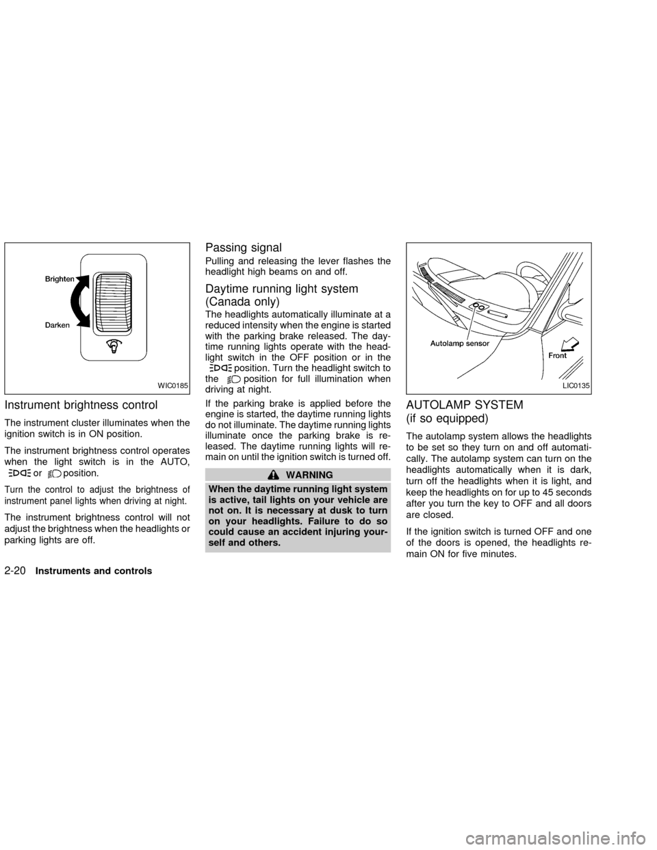
Instrument brightness control
The instrument cluster illuminates when the
ignition switch is in ON position.
The instrument brightness control operates
when the light switch is in the AUTO,
orposition.
Turn the control to adjust the brightness of
instrument panel lights when driving at night.
The instrument brightness control will not
adjust the brightness when the headlights or
parking lights are off.
Passing signal
Pulling and releasing the lever flashes the
headlight high beams on and off.
Daytime running light system
(Canada only)
The headlights automatically illuminate at a
reduced intensity when the engine is started
with the parking brake released. The day-
time running lights operate with the head-
light switch in the OFF position or in the
position. Turn the headlight switch to
theposition for full illumination when
driving at night.
If the parking brake is applied before the
engine is started, the daytime running lights
do not illuminate. The daytime running lights
illuminate once the parking brake is re-
leased. The daytime running lights will re-
main on until the ignition switch is turned off.
WARNING
When the daytime running light system
is active, tail lights on your vehicle are
not on. It is necessary at dusk to turn
on your headlights. Failure to do so
could cause an accident injuring your-
self and others.
AUTOLAMP SYSTEM
(if so equipped)
The autolamp system allows the headlights
to be set so they turn on and off automati-
cally. The autolamp system can turn on the
headlights automatically when it is dark,
turn off the headlights when it is light, and
keep the headlights on for up to 45 seconds
after you turn the key to OFF and all doors
are closed.
If the ignition switch is turned OFF and one
of the doors is opened, the headlights re-
main ON for five minutes.
WIC0185LIC0135
2-20Instruments and controls
ZX
Page 70 of 249

To set the autolamp system:
1. Make sure the headlight switch is in the
AUTO position.
2. Turn the ignition key to ON.
3. The autolamp system automatically turns
the headlights on and off.
To turn the autolamp system off, turn the
switch to the OFF,
,orposition.
Be sure you do not put anything on top
of the autolamp sensor located in the top
driver side of the instrument panel. The
autolamp sensor controls the autolamp;
if it is covered, the autolamp sensor
reacts as if it is dark out and the head-
lights will illuminate. If this occurs while
parked with the engine off and the key in
the ON position, your vehicle's battery
could become discharged.
TURN SIGNAL SWITCH
Turn signal
Move the lever up or down to signal the
turning direction. When the turn is com-
pleted, the turn signals cancel automati-
cally.
Lane change signal
To signal a lane change, move the lever up
or down to the point where the indicator light
begins to flash, but the lever does not latch.
Normal operation of the fog lights in the
ON
position:
Headlight switch in the AUTO position;
daytime operation
cFog lights, marker and taillights come
ON.
cHeadlights do not come ON.
cDash readouts dim unless the dimmer
switch is on full bright.
cIf the ignition switch is in the OFF position
with the fog lights turned ON, a warning
chime will sound indicating the fog lights
LIC0173
FOG LIGHT SWITCH (if so
equipped)
Instruments and controls2-21
ZX
Page 72 of 249
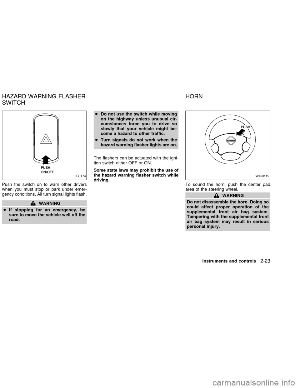
Push the switch on to warn other drivers
when you must stop or park under emer-
gency conditions. All turn signal lights flash.
WARNING
cIf stopping for an emergency, be
sure to move the vehicle well off the
road.cDo not use the switch while moving
on the highway unless unusual cir-
cumstances force you to drive so
slowly that your vehicle might be-
come a hazard to other traffic.
cTurn signals do not work when the
hazard warning flasher lights are on.
The flashers can be actuated with the igni-
tion switch either OFF or ON.
Some state laws may prohibit the use of
the hazard warning flasher switch while
driving.
To sound the horn, push the center pad
area of the steering wheel.
WARNING
Do not disassemble the horn. Doing so
could affect proper operation of the
supplemental front air bag system.
Tampering with the supplemental front
air bag system may result in serious
personal injury.
LIC0174WIC0119
HAZARD WARNING FLASHER
SWITCHHORN
Instruments and controls2-23
ZX
Page 85 of 249
WARNING
cDo not use the HomeLinkTUniversal
Transceiver with any garage door
opener that lacks safety stop and
reverse features as required by fed-
eral safety standards. (These stan-
dards became effective for opener
models manufactured after April 1,
1982). A garage door opener which
cannot detect an object in the path of
a closing garage door and then au-
tomatically stop and reverse, does
not meet current federal safety stan-
dards. Using a garage door opener
without these features increases the
risk of serious injury or death.
cDuring programming, your garage
door or gate may open or close.
Make sure that people and objects
are clear of the garage door or gate
that you are programming.
cYour vehicle's engine should be
turned off while programming the
HomeLinkTUniversal Transceiver.
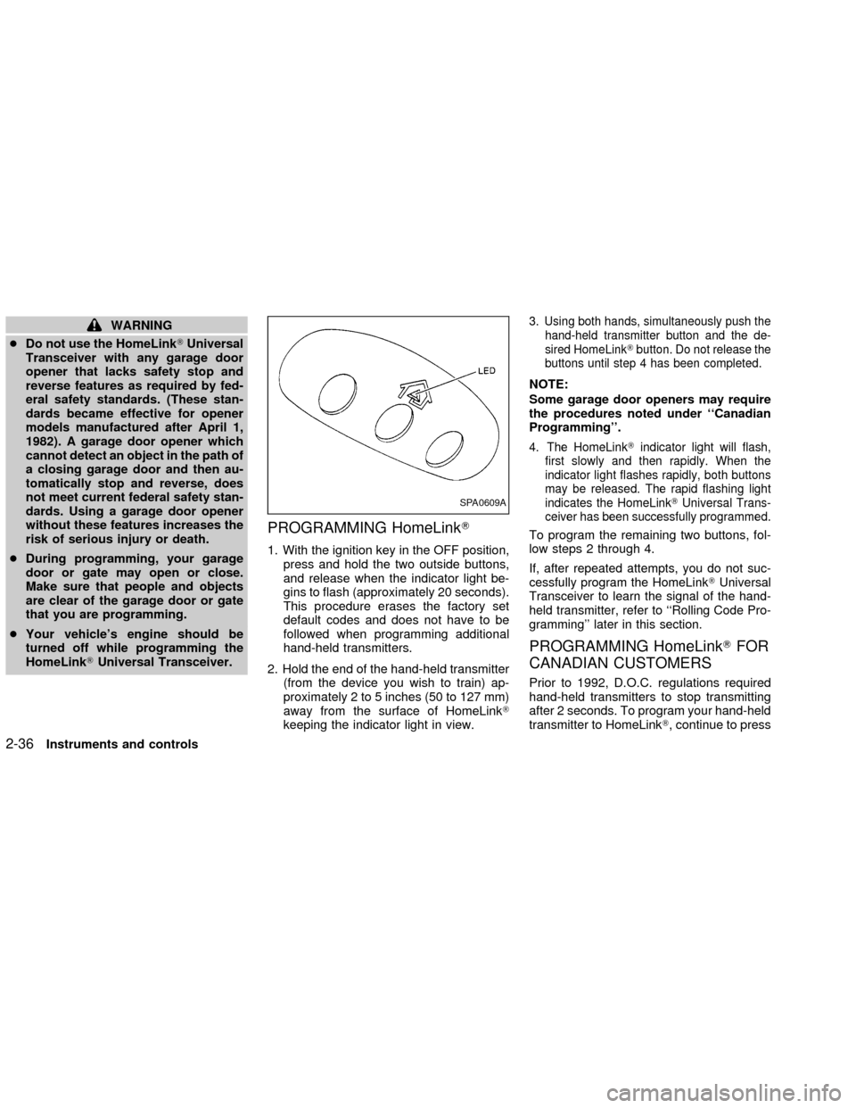
PROGRAMMING HomeLinkT
1. With the ignition key in the OFF position,
press and hold the two outside buttons,
and release when the indicator light be-
gins to flash (approximately 20 seconds).
This procedure erases the factory set
default codes and does not have to be
followed when programming additional
hand-held transmitters.
2. Hold the end of the hand-held transmitter
(from the device you wish to train) ap-
proximately 2 to 5 inches (50 to 127 mm)
away from the surface of HomeLinkT
keeping the indicator light in view.
3. Using both hands, simultaneously push the
hand-held transmitter button and the de-
sired HomeLinkTbutton. Do not release the
buttons until step 4 has been completed.
NOTE:
Some garage door openers may require
the procedures noted under ``Canadian
Programming''.
4. The HomeLinkTindicator light will flash,
first slowly and then rapidly. When the
indicator light flashes rapidly, both buttons
may be released. The rapid flashing light
indicates the HomeLinkTUniversal Trans-
ceiver has been successfully programmed.
To program the remaining two buttons, fol-
low steps 2 through 4.
If, after repeated attempts, you do not suc-
cessfully program the HomeLinkTUniversal
Transceiver to learn the signal of the hand-
held transmitter, refer to ``Rolling Code Pro-
gramming'' later in this section.
PROGRAMMING HomeLinkTFOR
CANADIAN CUSTOMERS
Prior to 1992, D.O.C. regulations required
hand-held transmitters to stop transmitting
after 2 seconds. To program your hand-held
transmitter to HomeLinkT, continue to press
SPA0609A
2-36Instruments and controls
ZX
Page 115 of 249

RADIO
Turn the ignition key to ACC or ON and
press the power on switch to turn on the
radio. If you listen to the radio with the
engine not running, the key should be
turned to the ACC position.
Radio reception is affected by station signal
strength, distance from radio transmitter,
buildings, bridges, mountains and other ex-
ternal influences. Intermittent changes in
reception quality normally are caused by
these external influences.
Using a cellular phone in or near the
vehicle may influence radio reception
quality.
Radio reception
Your NISSAN radio system is equipped with
state-of-the-art electronic circuits to en-
hance radio reception. These circuits are
designed to extend reception range, and to
enhance the quality of that reception.
However there are some general character-
istics of both FM and AM radio signals that
can affect radio reception quality in a mov-
ing vehicle, even when the finest equipment
is used. These characteristics are com-pletely normal in a given reception area,
and do not indicate any malfunction in your
NISSAN radio system.
Reception conditions will constantly change
because of vehicle movement. Buildings,
terrain, signal distance and interference
from other vehicles can work against ideal
reception. Described below are some of the
factors that can affect your radio reception.
FM RADIO RECEPTION
Range: FM range is normally limited to 25 to
30 miles (40 to 48 km), with monaural
(single channel) FM having slightly more
range than stereo FM. External influences
may sometimes interfere with FM station
reception even if the FM station is within 25
miles (40 km). The strength of the FM signal
is directly related to the distance between
the transmitter and receiver. FM signals
follow a line-of-sight path, exhibiting many
of the same characteristics as light. For
example they will reflect off objects.
Fade and drift: As your vehicle moves away
from a station transmitter, the signals will
tend to fade and/or drift.
Static and flutter: During signal interference
from buildings, large hills or due to antennaposition (usually in conjunction with in-
creased distance from the station transmit-
ter) static or flutter can be heard. This can
be reduced by adjusting the treble control
counterclockwise to reduce treble re-
sponse.
Multipath reception: Because of the reflec-
tive characteristics of FM signals, direct and
reflected signals reach the receiver at the
same time. The signals may cancel each
other, resulting in momentary flutter or loss
of sound.
AM RADIO RECEPTION
AM signals, because of their low frequency,
can bend around objects and skip along the
ground. In addition, the signals can be
bounced off the ionosphere and bent back
to earth. Because of these characteristics.
AM signals are also subject to interference
as they travel from transmitter to receiver.
Fading: Occurs while the vehicle is passing
through freeway underpasses or in areas
with many tall buildings. It can also occur for
several seconds during ionospheric turbu-
lence even in areas where no obstacles
exist.
Static: Caused by thunderstorms, electrical
AUDIO SYSTEM
4-12Heater, air conditioner and audio systems
ZX