charging NISSAN ALTIMA HYBRID 2010 L32A / 4.G Dismantling Guide
[x] Cancel search | Manufacturer: NISSAN, Model Year: 2010, Model line: ALTIMA HYBRID, Model: NISSAN ALTIMA HYBRID 2010 L32A / 4.GPages: 23, PDF Size: 3.09 MB
Page 3 of 23

Foreword
Nissan released the Altima Hybrid in North America in August of 2007. The Altima Hybrid runs on conventional
gasoline and a traction motor. The basic vehicle systems and features of the Altima Hybrid are the same as
those of the conventional Altima, except where noted in this guide. This Dismantling Guide was published to
help educate and assist the technician in the safe handling of the Altima Hybrid and its technology.
A high voltage battery is used to power the traction motor, generator, electric air conditioning compressor,
voltage converters, and inverter unit. A separate 12 volt battery is used to power other electrical devices such
as the radio, horn, headlamps, and instrument cluster gauges. A number of safeguards have been designed to
ensure that the high voltage Nickel Metal Hydride (Ni-MH) battery is kept safe and secure in the event of an
accident.
The Altima Hybrid utilizes both low and high voltage systems:
Low voltage system
• A 12 volt DC negative chassis ground body electrical system
High voltage system
• A 245 volt DC high voltage battery
• A harness that carries high voltage between the high voltage battery, converters, inverter unit, transaxle
and electric air conditioning compressor
• A converter which converts 245 volts DC to 42 volts DC for the electric power steering (EPS) system
• A converter which converts 245 volts DC to 12 volts DC for charging the 12 volt battery
• An inverter unit which delivers up to 650 volts AC to the transaxle
• A transaxle which houses a traction motor and generator
• A 245 volt DC, motor driven electric air conditioning compressor
High voltage electrical safety is an important factor in the dismantling of the Altima Hybrid. It is important to
recognize and understand the disabling procedures and warnings throughout this guide.
Additional topics in this guide include:
• Nissan Altima Hybrid identification
• Hybrid system component locations and descriptions
This Dismantling Guide is intended to assist the technician in the safe handling of a Nissan Altima Hybrid.
The information contained in this guide is somewhat simplified and intended to be used as a technical
reference. Please refer to the Nissan Service Manual for information related to vehicle repair.
- 3 -
Page 8 of 23

Hybrid System
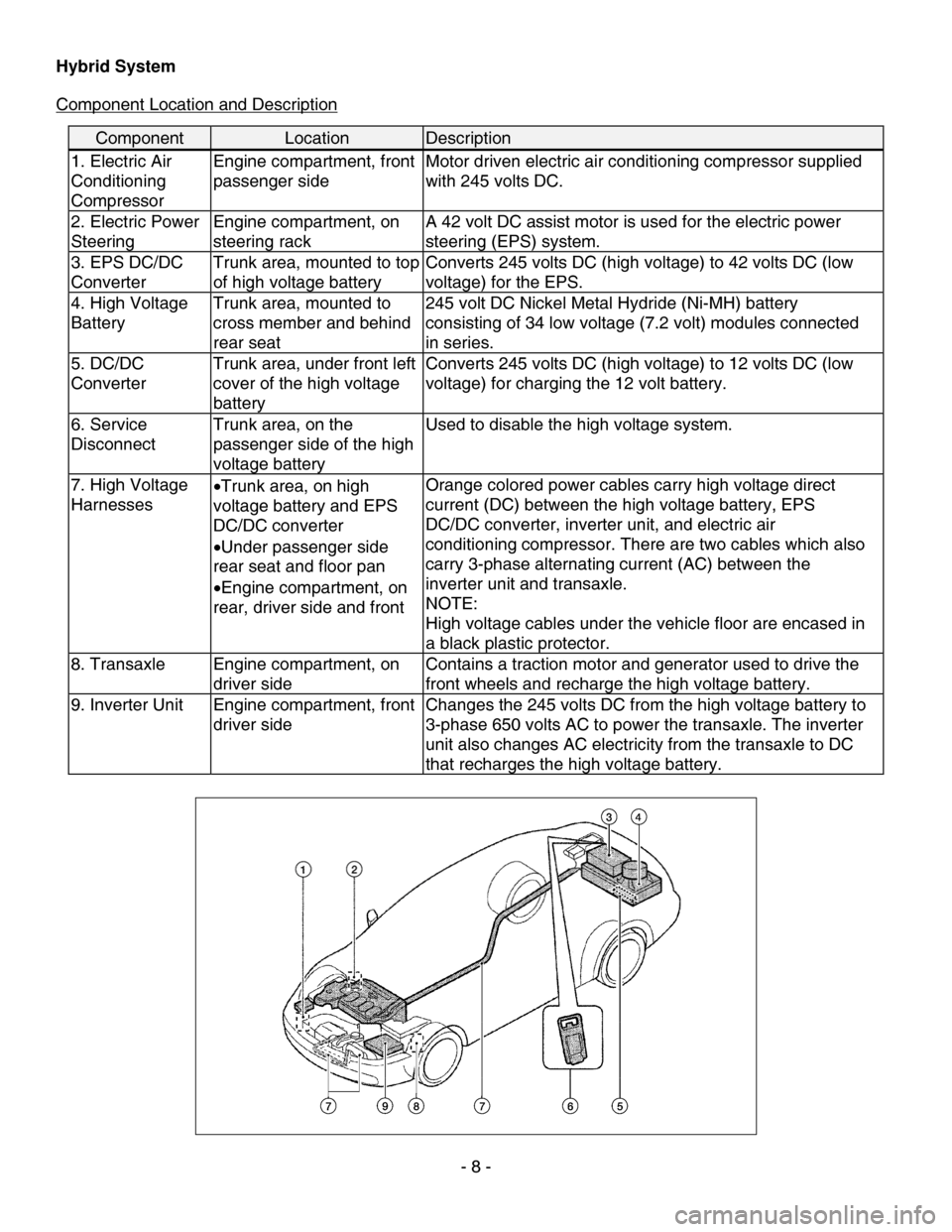
Component Location and Description
Component Location Description
1. Electric Air
Conditioning
Compressor Engine compartment, front
passenger side
Motor driven electric air conditioning compressor supplied
with 245 volts DC.
2. Electric Power
Steering Engine compartment, on
steering rack A 42 volt DC assist motor is used for the electric power
steering (EPS) system.
3. EPS DC/DC
Converter Trunk area, mounted to top
of high voltage battery Converts 245 volts DC (high voltage) to 42 volts DC (low
voltage) for the EPS.
4. High Voltage
Battery Trunk area, mounted to
cross member and behind
rear seat 245 volt DC Nickel Metal Hydride (Ni-MH) battery
consisting of 34 low voltage (7.2 volt) modules connected
in series.
5. DC/DC
Converter
Trunk area, under front left
cover of the high voltage
battery Converts 245 volts DC (high voltage) to 12 volts DC (low
voltage) for charging the 12 volt battery.
6. Service
Disconnect
Trunk area, on the
passenger side of the high
voltage battery Used to disable the high voltage system.
7. High Voltage
Harnesses
•
Trunk area, on high
voltage battery and EPS
DC/DC converter
• Under passenger side
rear seat and floor pan
• Engine compartment, on
rear, driver side and front Orange colored power cables carry high voltage direct
current (DC) between the high voltage battery, EPS
DC/DC converter, inverter unit, and electric air
conditioning compressor. There are two cables which also
carry 3-phase alternating current (AC) between the
inverter unit and transaxle.
NOTE:
High voltage cables under the vehicle floor are encased in
a black plastic protector.
8. Transaxle
Engine compartment, on
driver side Contains a traction motor and generator used to drive the
front wheels and recharge the high voltage battery.
9. Inverter Unit
Engine compartment, front
driver side Changes the 245 volts DC from the high voltage battery to
3-phase 650 volts AC to power the transaxle. The inverter
unit also changes AC electricity from the transaxle to DC
that recharges the high voltage battery.
- 8 -