engine NISSAN ALTIMA HYBRID 2010 L32A / 4.G Dismantling Guide
[x] Cancel search | Manufacturer: NISSAN, Model Year: 2010, Model line: ALTIMA HYBRID, Model: NISSAN ALTIMA HYBRID 2010 L32A / 4.GPages: 23, PDF Size: 3.09 MB
Page 2 of 23

- 2 -
Foreword .......................................................................\
....................................................... ....................... - 3 -
About the Nissan Altima Hybrid ........................................................................\
....................................... - 4 -
Altima Hybrid Identification ........................................................................\
.............................................. - 5 -
VIN Location ........................................................................\
......................................................................... - 5 -
Engine Compartment .......................................................................\
....................................................... ..... - 6 -
Exterior .......................................................................\
.................................................................................. - 7 -
Interior .......................................................................\
....................................................... ............................ - 7 -
Hybrid System .......................................................................\
....................................................... .............. - 8 -
Component Location and Description ........................................................................\
.................................. - 8 -
Battery Information .......................................................................\
....................................................... ...... - 9 -
Low Voltage Battery .......................................................................\
....................................................... ....... - 9 -
High Voltage Battery .......................................................................\
....................................................... ...... - 9 -
Recovery/Recycling of the Ni-MH High Voltage Battery ........................................................................\
.... - 10 -
High Voltage Safety .......................................................................\
....................................................... ... - 11 -
High Voltage Safety System ........................................................................\
.............................................. - 11 -
Precautions for Dismantling .......................................................................\
................................................ - 13 -
Spills ........................................................................\
................................................................................... - 13 -
First Aid .......................................................................\
....................................................... ........................ - 14 -
Vehicle Cut Sheet .......................................................................\
....................................................... ........ - 15 -
Dismantling the High Voltage System ........................................................................\
........................... - 16 -
Service Disconnect .......................................................................\
....................................................... ...... - 16 -
Alternative High Voltage System Shut Down Procedure ........................................................................\
... - 19 -
Removal of HV Battery ........................................................................\
....................................................... - 20 -
Removal of HV Components ........................................................................\
.............................................. - 23 -
Page 4 of 23

- 4 -
About the Nissan Altima Hybrid
There are two power sources stored on board that are used to drive the vehicle:
• Gasoline is stored in a fuel tank and is used to supply the gasoline engine.
• Electricity is stored in a high voltage battery and is used to power the traction motor.
The result of combining these two power sources is improved fuel economy and reduced emissions. The
gasoline engine also powers an electric generator to recharge the high voltage battery; unlike an entirely
electric vehicle, the Altima Hybrid never needs to be recharged from an external electric power source.
Depending on the driving conditions, one or both sources are used to drive the vehicle. The following
information explains how the Altima Hybrid operates in various driving modes:
1. During light acceleration at low speeds, the vehicle is driven by the traction motor. The gasoline engine
is shut off.
2. During normal driving, the vehicle is driven mainly by the gasoline engine. The gasoline engine also
powers the generator to recharge the high voltage battery.
3. During full acceleration, such as climbing a hill, both the gasoline engine and the traction motor drive
the vehicle.
4. During deceleration, such as when braking, the vehicle converts kinetic energy from the front wheels to
electricity that will recharge the high voltage battery.
5. While the vehicle is stopped, such as at a stoplight, both the gasoline engine and the traction motor are
off, however the vehicle remains operational.
Page 6 of 23

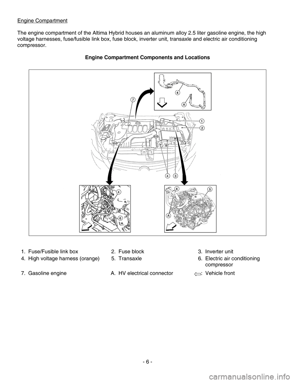
Engine Compartment
The engine compartment of the Altima Hybrid houses an aluminum alloy 2.5 liter gasoline engine, the high
voltage harnesses, fuse/fusible link box, fuse block, inverter unit, transaxle and electric air conditioning
compressor.
Engine Compartment Components and Locations
1.
Fuse/Fusible link box 2. Fuse block 3.Inverter unit
4. High voltage harness (orange) 5. Transaxle 6.Electric air conditioning
compressor
7. Gasoline engine A. HV electrical connector :Vehicle front
- 6 -
Page 8 of 23

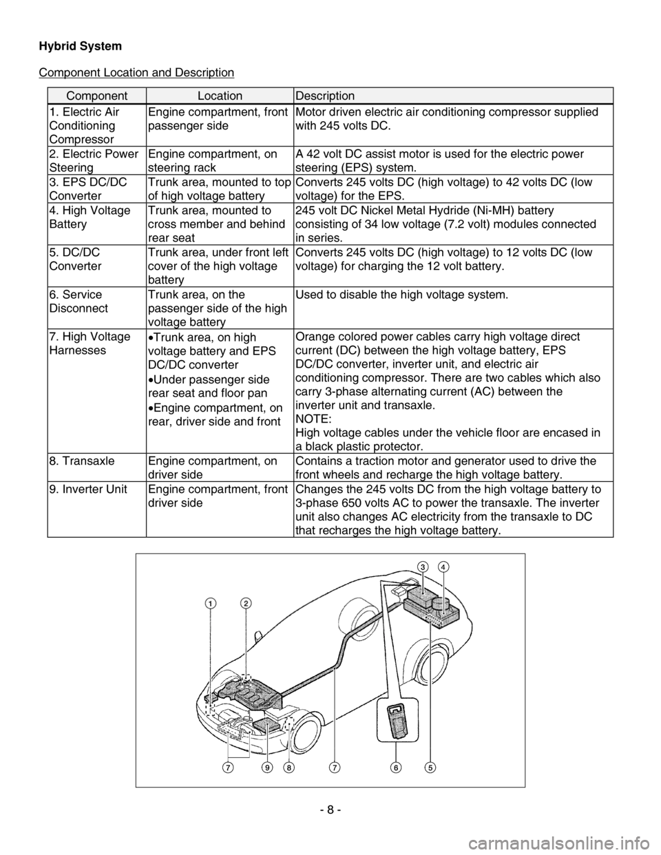
Hybrid System
Component Location and Description
Component Location Description
1. Electric Air
Conditioning
Compressor Engine compartment, front
passenger side
Motor driven electric air conditioning compressor supplied
with 245 volts DC.
2. Electric Power
Steering Engine compartment, on
steering rack A 42 volt DC assist motor is used for the electric power
steering (EPS) system.
3. EPS DC/DC
Converter Trunk area, mounted to top
of high voltage battery Converts 245 volts DC (high voltage) to 42 volts DC (low
voltage) for the EPS.
4. High Voltage
Battery Trunk area, mounted to
cross member and behind
rear seat 245 volt DC Nickel Metal Hydride (Ni-MH) battery
consisting of 34 low voltage (7.2 volt) modules connected
in series.
5. DC/DC
Converter
Trunk area, under front left
cover of the high voltage
battery Converts 245 volts DC (high voltage) to 12 volts DC (low
voltage) for charging the 12 volt battery.
6. Service
Disconnect
Trunk area, on the
passenger side of the high
voltage battery Used to disable the high voltage system.
7. High Voltage
Harnesses
•
Trunk area, on high
voltage battery and EPS
DC/DC converter
• Under passenger side
rear seat and floor pan
• Engine compartment, on
rear, driver side and front Orange colored power cables carry high voltage direct
current (DC) between the high voltage battery, EPS
DC/DC converter, inverter unit, and electric air
conditioning compressor. There are two cables which also
carry 3-phase alternating current (AC) between the
inverter unit and transaxle.
NOTE:
High voltage cables under the vehicle floor are encased in
a black plastic protector.
8. Transaxle
Engine compartment, on
driver side Contains a traction motor and generator used to drive the
front wheels and recharge the high voltage battery.
9. Inverter Unit
Engine compartment, front
driver side Changes the 245 volts DC from the high voltage battery to
3-phase 650 volts AC to power the transaxle. The inverter
unit also changes AC electricity from the transaxle to DC
that recharges the high voltage battery.
- 8 -