phone NISSAN ARMADA 2018 Owner´s Manual
[x] Cancel search | Manufacturer: NISSAN, Model Year: 2018, Model line: ARMADA, Model: NISSAN ARMADA 2018Pages: 532, PDF Size: 2.3 MB
Page 7 of 532
NISSAN CUSTOMER CARE PROGRAM
NISSAN CARES ...
Both NISSAN and your NISSAN dealer are dedicated to serving all your automotive needs. Your satisfaction with your vehicle and your
NISSAN dealer are our primary concerns. Your NISSAN dealer is always available to assist you with all your automobile sales and
service needs.
However, if there is something that your
NISSAN dealer cannot assist you with or
you would like to provide NISSAN directly
with comments or questions, please con-
tact the NISSAN Consumer Affairs Depart-
ment using our toll-free number:For U.S. customers1-800-NISSAN-1
(1-800-647-7261)
For Canadian customers 1-800-387-0122
The Consumer Affairs Department will
ask for the following information:
. Your name, address, and telephone
number
. Vehicle identification number (at-
tached to the top of the instrument
panel on the driver’s side)
. Date of purchase
. Current odometer reading
. Your NISSAN dealer’s name
. Your comments or questions
OR You can write to NISSAN with the infor-
mation at:
For U.S. customersNissan North America, Inc.
Consumer Affairs Department
P.O. Box 685003
Franklin, TN 37068-5003
or via e-mail at:
nnaconsumeraffairs@nissan-usa.
com
For Canadian customers Nissan Canada Inc.
5290 Orbitor Drive
Mississauga, Ontario L4W 4Z5
or via e-mail at:
information.centre@nissancana-
da.com If you prefer, visit us at:
www.nissanusa.com
(for U.S. customers)
or
www.nissan.ca (for Canadian customers)
We appreciate your interest in NISSAN
and thank you for buying a quality NISSAN
vehicle.
Page 8 of 532
Illustrated table of contents0
Safety — seats, seat belts and supplemental restraint
system1
Instruments and controls
Pre-driving checks and adjustments
Monitor, heater, air conditioner, audio, phone and voice
recognition systems
Starting and driving
In case of emergency
Appearance and care
Do-it-yourself
Maintenance and schedules
Technical and consumer information
2
3
4
5
6
7
8
9
10
Table of
Contents
Index11
Page 15 of 532
0-6Illustrated table of contents
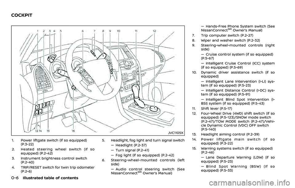
JVC1105X
1. Power liftgate switch (if so equipped)(P.3-22)
2. Heated steering wheel switch (if so equipped) (P.2-42)
3. Instrument brightness control switch (P.2-40)
4. TRIP/RESET switch for twin trip odometer (P.2-6) 5. Headlight, fog light and turn signal switch
— Headlight (P.2-37)
— Turn signal (P.2-41)
— Fog light (if so equipped) (P.2-42)
6. Steering-wheel-mounted controls (left side)
— Audio control steering switch (See
NissanConnect
SMOwner’s Manual) — Hands-Free Phone System switch (See
NissanConnect
SMOwner’s Manual)
7. Trip computer switch (P.2-27)
8. Wiper and washer switch (P.2-32)
9. Steering-wheel-mounted controls (right side)
— Cruise control system (if so equipped)
(P.5-67)
— Intelligent Cruise Control (ICC) system
(if so equipped) (P.5-69)
10. Dynamic driver assistance switch (if so equipped)
— Intelligent Lane Intervention (I-LI) sys-
tem (if so equipped) (P.5-23)
— Intelligent Distance Control (I-DC) sys-
tem (if so equipped) (P.5-91)
— Intelligent Blind Spot Intervention (I-
BSI) system (if so equipped) (P.5-43)
11. Shift lever (P.5-17)
12. Four-Wheel Drive (4WD) shift switch (if so equipped) (P.5-123)/SNOW mode switch
(P.2-47)/TOW MODE switch (P.2-47)/Vehi-
cle Dynamic Control (VDC) OFF switch
(P.5-140)
13. Headlight aiming control (P.2-39)
14. Power liftgate main switch (if so equipped) (P.3-22)
15. Warning systems switch (if so equipped) (P.2-46)
— Lane Departure Warning (LDW) (if so
equipped) (P.5-23)
— Blind Spot Warning (BSW) (if so
equipped) (P.5-33)
COCKPIT
Page 96 of 532
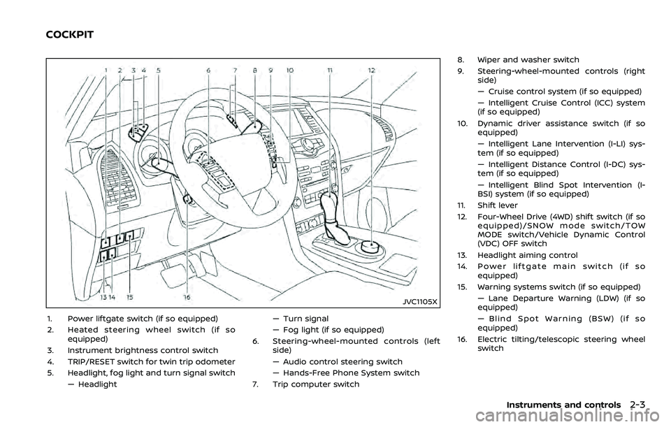
JVC1105X
1. Power liftgate switch (if so equipped)
2. Heated steering wheel switch (if soequipped)
3. Instrument brightness control switch
4. TRIP/RESET switch for twin trip odometer
5. Headlight, fog light and turn signal switch — Headlight — Turn signal
— Fog light (if so equipped)
6. Steering-wheel-mounted controls (left side)
— Audio control steering switch
— Hands-Free Phone System switch
7. Trip computer switch 8. Wiper and washer switch
9. Steering-wheel-mounted controls (right
side)
— Cruise control system (if so equipped)
— Intelligent Cruise Control (ICC) system
(if so equipped)
10. Dynamic driver assistance switch (if so equipped)
— Intelligent Lane Intervention (I-LI) sys-
tem (if so equipped)
— Intelligent Distance Control (I-DC) sys-
tem (if so equipped)
— Intelligent Blind Spot Intervention (I-
BSI) system (if so equipped)
11. Shift lever
12. Four-Wheel Drive (4WD) shift switch (if so equipped)/SNOW mode switch/TOW
MODE switch/Vehicle Dynamic Control
(VDC) OFF switch
13. Headlight aiming control
14. Power liftgate main switch (if so equipped)
15. Warning systems switch (if so equipped) — Lane Departure Warning (LDW) (if so
equipped)
— Blind Spot Warning (BSW) (if so
equipped)
16. Electric tilting/telescopic steering wheel switch
Instruments and controls2-3
COCKPIT
Page 142 of 532
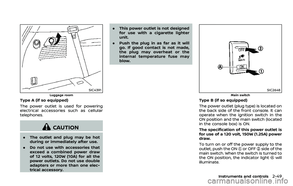
SIC4391
Luggage room
Type A (if so equipped)
The power outlet is used for powering
electrical accessories such as cellular
telephones.
CAUTION
.The outlet and plug may be hot
during or immediately after use.
. Do not use with accessories that
exceed a combined power draw
of 12 volts, 120W (10A) for all the
power outlets. Do not use double
adapters or more than one elec-
trical accessory. .
This power outlet is not designed
for use with a cigarette lighter
unit.
. Push the plug in as far as it will
go. If good contact is not made,
the plug may overheat or the
internal temperature fuse may
blow.
SIC2648
Main switch
Type B (if so equipped)
The power outlet (plug type) is located on
the back side of the front console. It can
operate when the ignition switch in the
ON position and the main switch (located
in the console box) is ON.
The specification of this power outlet is
for use of a 120 volt, 150W (1.25A) power
draw.
To turn on or off the power supply to the
outlet, push the ON
or OFFside of the
main switch. When the switch is turned to
the ON position, the indicator light
will
illuminate.
Instruments and controls2-49
Page 176 of 532
WARNING
.Radio waves could adversely af-
fect electric medical equipment.
Those who use a pacemaker
should contact the electric med-
ical equipment manufacturer for
the possible influences before
use.
. The Intelligent Key transmits
radio waves when the buttons
are pushed. The FAA advises that
the radio waves may affect air-
craft navigation and communica-
tion systems. Do not operate the
Intelligent Key while on an air-
plane. Make sure the buttons are
not operated unintentionally
when the unit is stored during a
flight.
The Intelligent Key system can operate all
the door locks using the remote control-
ler function or pushing the request switch
on the vehicle without taking the key out
from a pocket or purse. The operating
environment and/or conditions may af-
fect the Intelligent Key system operation.
Be sure to read the following before using
the Intelligent Key system.
CAUTION
. Be sure to carry the Intelligent
Key with you when operating the
vehicle.
. Never leave the Intelligent Key in
the vehicle when you leave the
vehicle.
The Intelligent Key is always communi-
cating with the vehicle as it receives radio
waves. The Intelligent Key system trans-
mits weak radio waves. Environmental
conditions may interfere with the opera-
tion of the Intelligent Key system under
the following operating conditions.
. When operating near a location where
strong radio waves are transmitted,
such as a TV tower, power station and
broadcasting station.
. When in possession of wireless equip-
ment, such as a cellular telephone,
transceiver, and CB radio.
. When the Intelligent Key is in contact
with or covered by metallic materials.
. When any type of radio wave remote
control is used nearby.
. When the Intelligent Key is placed near
an electric appliance such as a perso-
nal computer. .
When the vehicle is parked near a
parking meter.
In such cases, correct the operating
conditions before using the Intelligent
Key function or use the mechanical key.
Although the life of the battery varies
depending on the operating conditions,
the battery’s life is approximately 2 years.
If the battery is discharged, replace it with
a new one.
Since the Intelligent Key is continuously
receiving radio waves, if the key is left
near equipment which transmits strong
radio waves, such as signals from a TV
and personal computer, the battery life
may become shorter.
For information regarding replacement of
a battery, see “Intelligent Key battery
replacement” (P.8-21).
As many as 4 Intelligent Keys can be
registered and used with one vehicle. For
information about the purchase and use
of additional Intelligent Keys, contact a
NISSAN dealer.
CAUTION
. Do not allow the Intelligent Key,
which contains electrical compo-
nents, to come into contact with
water or salt water. This could
Pre-driving checks and adjustments3-7
INTELLIGENT KEY SYSTEM
Page 212 of 532
4 Monitor, heater, air conditioner, audio,phone and voice recognition systems
NissanConnectSMOwner’s Manual ................................. 4-2
Safety note ........................................................................\
................ 4-2
RearView Monitor (if so equipped) ................................. 4-3
RearView Monitor system operation ..................... 4-4
How to read the displayed lines ................................ 4-4
Difference between predictive and
actual distances ...................................................................... 4-4
How to park with predictive course lines .......... 4-6
Sonar indicator ........................................................................\
4-7
Adjusting the screen ........................................................... 4-7
Predictive course line settings .................................... 4-8
RearView Monitor system limitations .................... 4-8
System maintenance .......................................................... 4-9
Intelligent Around View Monitor (if
so equipped) ........................................................................\
.......... 4-10 Intelligent Around View Monitor
system operation ................................................................ 4-11
How to adjust the screen view ................................ 4-19
Intelligent Around View Monitor settings ....... 4-19
Intelligent Around View Monitor
system limitations .............................................................. 4-21
System maintenance ....................................................... 4-23
Camera aiding sonar function (models with
Intelligent Around View Monitor) .................................. 4-24 Sonar system operation ................................................ 4-24 Turning on and off the sonar function .......... 4-25
Sonar system limitations ........................................... 4-26
System temporarily unavailable ........................... 4-27
System maintenance .................................................... 4-27
Moving Object Detection (MOD) ................................... 4-28 MOD system operation ................................................ 4-29
Turning on and off the MOD system ............... 4-30
MOD system limitations .............................................. 4-31
System maintenance .................................................... 4-32
Ventilators ........................................................................\
.............. 4-33
Center ventilators ............................................................ 4-33
Side ventilators .................................................................. 4-33
Rear ventilators .................................................................. 4-33
Heater and air conditioner ................................................ 4-34 Automatic air conditioner ......................................... 4-35
Rear automatic air conditioning system ....... 4-38
Operating tips ..................................................................... 4-42
Linking Intelligent Key (if so equipped) ........... 4-42
In-cabin microfilter .......................................................... 4-42
Servicing air conditioner ............................................. 4-42
Antenna ........................................................................\
.................... 4-42 Window antenna ............................................................... 4-42
Satellite antenna ............................................................... 4-43
Car phone or CB radio ......................................................... 4-43
Page 213 of 532
4-2Monitor, heater, air conditioner, audio, phone and voice recognition systems
For models with NissanConnectSMwith
Navigation (if so equipped), Apps and
Services (if so equipped), refer to the
NissanConnect
SMOwner’s Manual re-
garding the following information.
. Audio system
. Bluetooth® Hands-Free Phone
. NissanConnect
SMApps
. NissanConnectSMServices
. Navigation system
. Voice recognition
. Information and settings viewable on
NissanConnect
SM
WARNING
.Do not disassemble or modify
this system. If you do, it may
result in accidents, fire, or electric
shock.
. Do not use this system if you
notice any abnormality, such as
a frozen screen or lack of sound.
Continued use of the system may
result in accident, fire or electric
shock.
. In case you notice any foreign
object in the system hardware,
spill liquid on it, or notice smoke
or smell coming from it, stop
using the system immediately. It
is recommended you visit a
NISSAN dealer for servicing.
Ignoring such conditions may
lead to accidents, fire, or electric
shock.
. Park the vehicle in a safe location
and apply the parking brake to
view the images on the front
center display screen.
CAUTION
Do not use the system when the
engine is not running for extended
periods of time to prevent battery
discharge.
Do not attempt to operate the system in
extreme temperature conditions [below
−4°F (−20°C) and above 158°F (70°C)].
Operating this system under these con-
ditions may result in system malfunc-
tions.
NISSANCONNECTSMOWNER’S MANUALSAFETY NOTE
Page 214 of 532
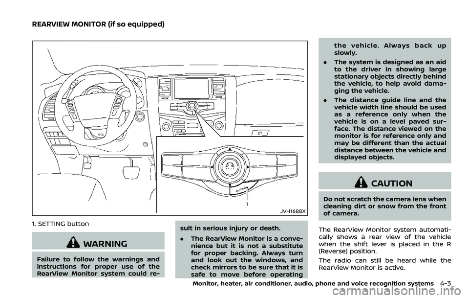
JVH1688X
1. SETTING button
WARNING
Failure to follow the warnings and
instructions for proper use of the
RearView Monitor system could re-sult in serious injury or death.
.
The RearView Monitor is a conve-
nience but it is not a substitute
for proper backing. Always turn
and look out the windows, and
check mirrors to be sure that it is
safe to move before operating the vehicle. Always back up
slowly.
. The system is designed as an aid
to the driver in showing large
stationary objects directly behind
the vehicle, to help avoid dama-
ging the vehicle.
. The distance guide line and the
vehicle width line should be used
as a reference only when the
vehicle is on a level paved sur-
face. The distance viewed on the
monitor is for reference only and
may be different than the actual
distance between the vehicle and
displayed objects.
CAUTION
Do not scratch the camera lens when
cleaning dirt or snow from the front
of camera.
The RearView Monitor system automati-
cally shows a rear view of the vehicle
when the shift lever is placed in the R
(Reverse) position.
The radio can still be heard while the
RearView Monitor is active.
Monitor, heater, air conditioner, audio, phone and voice recognition systems4-3
REARVIEW MONITOR (if so equipped)
Page 215 of 532
4-4Monitor, heater, air conditioner, audio, phone and voice recognition systems
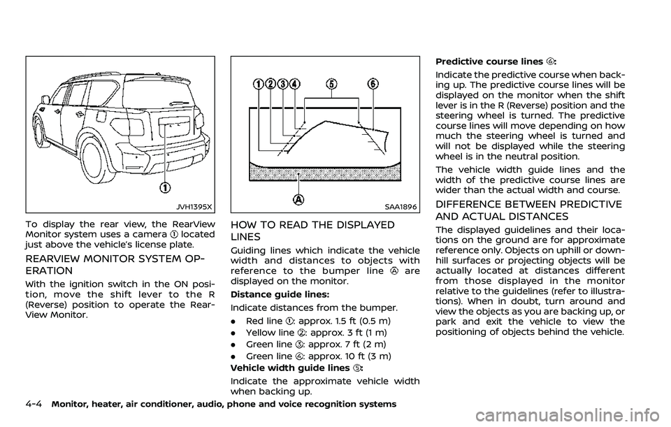
JVH1395X
To display the rear view, the RearView
Monitor system uses a cameralocated
just above the vehicle’s license plate.
REARVIEW MONITOR SYSTEM OP-
ERATION
With the ignition switch in the ON posi-
tion, move the shift lever to the R
(Reverse) position to operate the Rear-
View Monitor.
SAA1896
HOW TO READ THE DISPLAYED
LINES
Guiding lines which indicate the vehicle
width and distances to objects with
reference to the bumper line
are
displayed on the monitor.
Distance guide lines:
Indicate distances from the bumper.
. Red line
: approx. 1.5 ft (0.5 m)
. Yellow line
: approx. 3 ft (1 m)
. Green line
: approx. 7 ft (2 m)
. Green line
: approx. 10 ft (3 m)
Vehicle width guide lines
:
Indicate the approximate vehicle width
when backing up. Predictive course lines
:
Indicate the predictive course when back-
ing up. The predictive course lines will be
displayed on the monitor when the shift
lever is in the R (Reverse) position and the
steering wheel is turned. The predictive
course lines will move depending on how
much the steering wheel is turned and
will not be displayed while the steering
wheel is in the neutral position.
The vehicle width guide lines and the
width of the predictive course lines are
wider than the actual width and course.
DIFFERENCE BETWEEN PREDICTIVE
AND ACTUAL DISTANCES
The displayed guidelines and their loca-
tions on the ground are for approximate
reference only. Objects on uphill or down-
hill surfaces or projecting objects will be
actually located at distances different
from those displayed in the monitor
relative to the guidelines (refer to illustra-
tions). When in doubt, turn around and
view the objects as you are backing up, or
park and exit the vehicle to view the
positioning of objects behind the vehicle.