power steering NISSAN ARMADA 2018 Owner´s Manual
[x] Cancel search | Manufacturer: NISSAN, Model Year: 2018, Model line: ARMADA, Model: NISSAN ARMADA 2018Pages: 532, PDF Size: 2.3 MB
Page 15 of 532
0-6Illustrated table of contents
JVC1105X
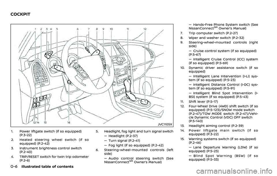
1. Power liftgate switch (if so equipped)(P.3-22)
2. Heated steering wheel switch (if so equipped) (P.2-42)
3. Instrument brightness control switch (P.2-40)
4. TRIP/RESET switch for twin trip odometer (P.2-6) 5. Headlight, fog light and turn signal switch
— Headlight (P.2-37)
— Turn signal (P.2-41)
— Fog light (if so equipped) (P.2-42)
6. Steering-wheel-mounted controls (left side)
— Audio control steering switch (See
NissanConnect
SMOwner’s Manual) — Hands-Free Phone System switch (See
NissanConnect
SMOwner’s Manual)
7. Trip computer switch (P.2-27)
8. Wiper and washer switch (P.2-32)
9. Steering-wheel-mounted controls (right side)
— Cruise control system (if so equipped)
(P.5-67)
— Intelligent Cruise Control (ICC) system
(if so equipped) (P.5-69)
10. Dynamic driver assistance switch (if so equipped)
— Intelligent Lane Intervention (I-LI) sys-
tem (if so equipped) (P.5-23)
— Intelligent Distance Control (I-DC) sys-
tem (if so equipped) (P.5-91)
— Intelligent Blind Spot Intervention (I-
BSI) system (if so equipped) (P.5-43)
11. Shift lever (P.5-17)
12. Four-Wheel Drive (4WD) shift switch (if so equipped) (P.5-123)/SNOW mode switch
(P.2-47)/TOW MODE switch (P.2-47)/Vehi-
cle Dynamic Control (VDC) OFF switch
(P.5-140)
13. Headlight aiming control (P.2-39)
14. Power liftgate main switch (if so equipped) (P.3-22)
15. Warning systems switch (if so equipped) (P.2-46)
— Lane Departure Warning (LDW) (if so
equipped) (P.5-23)
— Blind Spot Warning (BSW) (if so
equipped) (P.5-33)
COCKPIT
Page 17 of 532
0-8Illustrated table of contents
JVC1093X
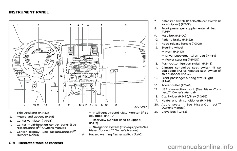
1. Side ventilator (P.4-33)
2. Meters and gauges (P.2-5)
3. Center ventilator (P.4-33)
4. Center multi-function control panel (SeeNissanConnect
SMOwner’s Manual)
5. Center display (See NissanConnectSM
Owner’s Manual) — Intelligent Around View Monitor (if so
equipped) (P.4-10)
— RearView Monitor (if so equipped)
(P.4-3)
— Navigation system (if so equipped) (See
NissanConnect
SMOwner’s Manual)
6. Hazard warning flasher switch (P.6-2) 7. Defroster switch (P.2-36)/Deicer switch (if
so equipped) (P.2-36)
8. Front passenger supplemental air bag (P.1-54)
9. Fuse box (P.8-20)
10. Parking brake (P.5-22)
11. Hood release handle (P.3-21)
12. Steering wheel — Horn (P.2-43)
— Driver supplemental air bag (P.1-54)
— Power steering (P.5-137)
13. Push-button ignition switch (P.5-13)
14. Climate controlled seat switch (if so equipped) (P.2-45)/Heated seat switch (if
so equipped) (P.2-43)
15. Front passenger air bag status light (P.1-62)
16. Power outlet (P.2-48)
17. USB connection port (See NissanCon- nect
SMOwner’s Manual)
18. Cup holder (P.2-51)/Tray (P.2-55)
19. Heater and air conditioner (P.4-34)
20. Audio system (See NissanConnect
SM
Owner’s Manual)
21. Glove box (P.2-53)
INSTRUMENT PANEL
Page 19 of 532
0-10Illustrated table of contents
JVC0965X
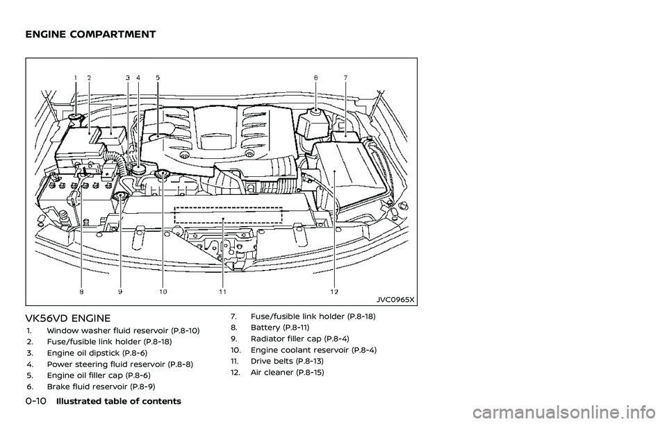
VK56VD ENGINE
1. Window washer fluid reservoir (P.8-10)
2. Fuse/fusible link holder (P.8-18)
3. Engine oil dipstick (P.8-6)
4. Power steering fluid reservoir (P.8-8)
5. Engine oil filler cap (P.8-6)
6. Brake fluid reservoir (P.8-9)7. Fuse/fusible link holder (P.8-18)
8. Battery (P.8-11)
9. Radiator filler cap (P.8-4)
10. Engine coolant reservoir (P.8-4)
11. Drive belts (P.8-13)
12. Air cleaner (P.8-15)
ENGINE COMPARTMENT
Page 96 of 532
JVC1105X
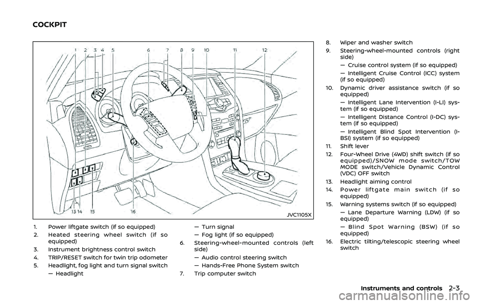
1. Power liftgate switch (if so equipped)
2. Heated steering wheel switch (if soequipped)
3. Instrument brightness control switch
4. TRIP/RESET switch for twin trip odometer
5. Headlight, fog light and turn signal switch — Headlight — Turn signal
— Fog light (if so equipped)
6. Steering-wheel-mounted controls (left side)
— Audio control steering switch
— Hands-Free Phone System switch
7. Trip computer switch 8. Wiper and washer switch
9. Steering-wheel-mounted controls (right
side)
— Cruise control system (if so equipped)
— Intelligent Cruise Control (ICC) system
(if so equipped)
10. Dynamic driver assistance switch (if so equipped)
— Intelligent Lane Intervention (I-LI) sys-
tem (if so equipped)
— Intelligent Distance Control (I-DC) sys-
tem (if so equipped)
— Intelligent Blind Spot Intervention (I-
BSI) system (if so equipped)
11. Shift lever
12. Four-Wheel Drive (4WD) shift switch (if so equipped)/SNOW mode switch/TOW
MODE switch/Vehicle Dynamic Control
(VDC) OFF switch
13. Headlight aiming control
14. Power liftgate main switch (if so equipped)
15. Warning systems switch (if so equipped) — Lane Departure Warning (LDW) (if so
equipped)
— Blind Spot Warning (BSW) (if so
equipped)
16. Electric tilting/telescopic steering wheel switch
Instruments and controls2-3
COCKPIT
Page 97 of 532
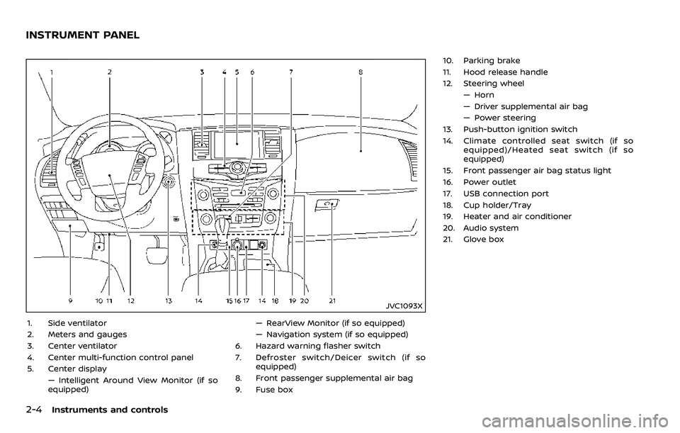
2-4Instruments and controls
JVC1093X
1. Side ventilator
2. Meters and gauges
3. Center ventilator
4. Center multi-function control panel
5. Center display— Intelligent Around View Monitor (if so
equipped) — RearView Monitor (if so equipped)
— Navigation system (if so equipped)
6. Hazard warning flasher switch
7. Defroster switch/Deicer switch (if so equipped)
8. Front passenger supplemental air bag
9. Fuse box 10. Parking brake
11. Hood release handle
12. Steering wheel
— Horn
— Driver supplemental air bag
— Power steering
13. Push-button ignition switch
14. Climate controlled seat switch (if so equipped)/Heated seat switch (if so
equipped)
15. Front passenger air bag status light
16. Power outlet
17. USB connection port
18. Cup holder/Tray
19. Heater and air conditioner
20. Audio system
21. Glove box
INSTRUMENT PANEL
Page 170 of 532
3 Pre-driving checks and adjustments
Keys ........................................................................\
................................. 3-2Intelligent Key ........................................................................\
... 3-2
Valet hand-off ........................................................................\
... 3-4
Doors ........................................................................\
.............................. 3-4 Locking with mechanical key ...................................... 3-4
Opening and closing windows with the
mechanical key ........................................................................\
3-5
Locking with inside lock knob ..................................... 3-5
Locking with power door lock switch ................... 3-5
Automatic door locks ......................................................... 3-6
Child safety rear door lock ........................................... 3-6
Intelligent Key system .............................................................. 3-7 Intelligent Key operating range ................................. 3-9
Door locks/unlocks precaution .................................. 3-9
Intelligent Key operation .............................................. 3-10
Battery saver system ....................................................... 3-12
Warning signals .................................................................... 3-12
Troubleshooting guide ................................................... 3-13
Remote keyless entry system ......................................... 3-15 How to use remote keyless entry system ...... 3-16
Remote engine start (if so equipped) ....................... 3-19 Remote engine start operating range ............... 3-19
Remote starting the engine ....................................... 3-19
Extending engine run time ......................................... 3-20 Canceling a remote start ........................................... 3-20
Conditions the remote engine start will
not work ........................................................................\
.......... 3-20
Hood ........................................................................\
............................ 3-21
Liftgate ........................................................................\
...................... 3-22 Operating manual liftgate ......................................... 3-22
Operating power liftgate (if so equipped) ...... 3-22
Auto closure ........................................................................\
3-25
Liftgate release lever ..................................................... 3-26
Fuel-filler door ........................................................................\
..... 3-26
Opening the fuel-filler door ...................................... 3-26
Fuel-filler cap ....................................................................... 3-27
Tilt/telescopic steering ........................................................ 3-29
Electric operation ............................................................. 3-30
Sun visors ........................................................................\
................ 3-30
Mirrors ........................................................................\
........................ 3-31
Inside mirror ........................................................................\
. 3-31
Outside mirrors .................................................................. 3-38
Vanity mirror ........................................................................\
3-40
Automatic drive positioner (if so equipped) ........ 3-40
Entry/exit function .......................................................... 3-40
Memory storage ................................................................ 3-41
Setting memory function ........................................... 3-42
System operation ............................................................. 3-42
Page 211 of 532
3-42Pre-driving checks and adjustments
Confirming memory storage
.Push the ignition switch to the ON
position and push the SET switch. If
the main memory has not been
stored, the indicator light will come
on for approximately 0.5 second.
When the memory has stored in posi-
tion, the indicator light will stay on for
approximately 5 seconds.
. If the battery cable is disconnected, or
if the fuse opens, the memory will be
canceled. In this case, reset the de-
sired position using the previous pro-
cedure.
. If optional Intelligent Keys are added
to your vehicle, the memory storage
procedure to switch 1 or 2 and linking
Intelligent Key procedure to a stored
memory position should be per-
formed again for each Intelligent Key.
For additional Intelligent Key informa-
tion, see “Keys” (P.3-2).
Selecting the memorized position
1. Move the shift lever to the P (Park)
position.
2. Use one of the following methods to move the driver’s seat, the outside
mirrors and the steering wheel.
.Push the memory switch (1 or 2)fully for at least 1 second. The driver’s seat, steering column and
outside mirrors will move to the
memorized position or to the exit
position when the entry/exit function
is set to active with the indicator light
flashing, and then the light will stay on
for approximately 5 seconds.
SETTING MEMORY FUNCTION
The status of the following settings can
be linked to the Intelligent Key and the
memorized settings can be available for
each Intelligent Key.
.
Air conditioner system
. Navigation system (if so equipped)
. Audio system
To use the memory function, lock the
doors with the Intelligent Key that is
linked to the settings.
To enable the memorized settings:
1. Carry the Intelligent Key that is linked to the settings, and unlock the doors
by pushing the driver’s door handle
request switch or “UNLOCK”
but-
ton on the Intelligent Key.
2. Place the ignition switch in the ON position. “Connection with the key has
been done” will be displayed on the
screen and the memorized settings
are available (only when a new Intel-
ligent Key is used).
SYSTEM OPERATION
The automatic drive positioner system
will not work or will stop operating under
the following conditions:
.When the vehicle speed is above 0
MPH (0 km/h) or 4 MPH (7 km/h) for
some limited functions such linking an
Intelligent Key to the vehicle when the
power source is turned on from off or
during the Exit function.
. When any of the memory switches are
pushed while the automatic drive
positioner is operating.
. When the adjusting switch for the
driver’s seat and steering column is
turned on while the automatic drive
positioner is operating.
. When the seat has already been
moved to the memorized position.
. When no seat position is stored in the
memory switch.
. When the shift lever is moved from the
P (Park) position to any other position.
Page 258 of 532
Fuel efficient driving tips ................................................. 5-122
Increasing fuel economy ................................................. 5-123
NISSAN all-mode 4WD® (if so equipped) ............. 5-123NISSAN all-mode 4WD® system ........................... 5-124
4WD shift switch .............................................................. 5-128
4WD shift indicator ........................................................ 5-129
4WD warning light ......................................................... 5-129
Hill Start Assist system ...................................................... 5-131
Parking/parking on hills ................................................... 5-132
TOW mode ........................................................................\
.......... 5-133
SNOW mode ........................................................................\
....... 5-134
Sonar system (if so equipped) .................................... 5-134 Sonar settings ................................................................... 5-135
Sonar indicator ................................................................. 5-136
Power steering ........................................................................\
5-137
Brake system ........................................................................\
.... 5-137 Braking precautions ..................................................... 5-137
Parking brake break-in ............................................... 5-138 Brake assist ........................................................................\
....... 5-138
Brake assist ....................................................................... 5-138
Anti-lock Braking System (ABS) ........................ 5-138
Vehicle Dynamic Control (VDC) system .............. 5-140
Vehicle Dynamic Control (VDC)
OFF switch ........................................................................\
. 5-141
Cold weather driving ......................................................... 5-142 Freeing a frozen door lock ................................... 5-142
Antifreeze ........................................................................\
.... 5-142
Battery ........................................................................\
........... 5-142
Draining of coolant water ..................................... 5-142
Tire equipment ............................................................... 5-142
Special winter equipment ..................................... 5-143
Driving on snow or ice ............................................. 5-143
Engine block heater (if so equipped) ........... 5-143
Page 263 of 532
5-8Starting and driving
TPMS with Easy Fill Tire Alert
When adding air to an under-inflated tire,
the TPMS with Easy Fill Tire Alert provides
visual and audible signals outside the
vehicle to help you inflate the tires to
the recommended COLD tire pressure.
Vehicle set-up:
1. Park the vehicle in a safe and levelplace.
2. Apply the parking brake and place the shift lever in the P (Park) position.
3. Place the ignition switch in the ON position. Do not start the engine.
Operation:
1. Add air to the tire.
2. After a few seconds, the hazard in- dicators will start flashing.
3. When the designated pressure is reached, the horn beeps once and
the hazard indicators stop flashing.
4. Perform the above steps for each tire.
. If the tire is over-inflated more than
approximately 4 psi (30 kPa), the horn
beeps and the hazard indicators flash
3 times. To correct the pressure, push
the core of the valve stem on the tire
briefly to release pressure. When the
pressure reaches the designated
pressure, the horn beeps once. .
If the hazard indicator does not flash
within approximately 15 seconds after
starting to inflate the tire, it indicates
that the TPMS with Easy Fill Tire Alert
is not operating.
. The TPMS will not activate the Easy Fill
Tire Alert under the following condi-
tions:
— If there is interference from an
external device or transmitter
— The air pressure from the inflation device such as those using a power
socket is not sufficient to inflate the
tire
— If an electrical equipment is being used in or near the vehicle
— There is a malfunction in the TPMS system
— There is a malfunction in the horn or hazard indicators
. If the TPMS with Easy Fill Tire Alert
does not operate due to TPMS inter-
ference, move the vehicle about 3 ft
(1m) backward or forward and try
again.
If the TPMS with Easy Fill Tire Alert is not
working, use a tire pressure gauge.
AVOIDING COLLISION AND ROLL-
OVER
WARNING
Failure to operate this vehicle in a
safe and prudent manner may result
in loss of control or an accident.
Be alert and drive defensively at all times.
Obey all traffic regulations. Avoid exces-
sive speed, high speed cornering, or
sudden steering maneuvers, because
these driving practices could cause you
to lose control of your vehicle. As with
any vehicle, a loss of control could
result in a collision with other vehicles
or objects, or cause the vehicle to roll-
over, particularly if the loss of control
causes the vehicle to slide sideways. Be
attentive at all times, and avoid driving
when tired. Never drive when under the
influence of alcohol or drugs (including
prescription or over-the-counter drugs
which may cause drowsiness). Always
wear your seat belt as outlined in the
“Seat belts” (P.1-20), and also instruct your
passengers to do so.
Seat belts help reduce the risk of injury in
collisions and rollovers. In a rollover
crash, an unbelted or improperly belted
Page 392 of 532
the Sonar settings on the center display.
(See “Sonar settings” (P.5-135).) When the
sonar indicator is off, only a tone sounds
when the sonar detect obstacles.
WARNING
If the engine is not running or is
turned off while driving, the power
assist for the steering will not work.
Steering will be harder to operate.
The power assisted steering uses a hy-
draulic pump, driven by the engine, to
assist steering.
If the engine stops or the drive belt
breaks, you will still have control of the
vehicle. However, much greater steering
effort is needed, especially in sharp turns
and at low speeds.
BRAKING PRECAUTIONS
The brake system has two separate
hydraulic circuits. If one circuit malfunc-
tions, you will still have braking ability at
two wheels.
You may feel a small click and hear a
sound when the brake pedal is fully
depressed slowly. This is not a malfunc-
tion and indicates that the brake assist
mechanism is operating properly.
Hydraulically-assisted brakes
The hydraulically-assisted brake system is
designed to use a hydraulic pump driven
electrically, to assist braking. If the engine
stops, you can stop the vehicle by de-
pressing the foot brake pedal. However,
greater foot pressure on the foot brake
pedal will be required to stop the vehicle.
The stopping distance will be longer.
Wet brakes
When the vehicle is washed or driven
through water, the brakes may get wet.
As a result, your braking distance will be
longer and the vehicle may pull to one
side during braking.
To dry brakes, drive the vehicle at a safe
speed while lightly tapping the brake
pedal to heat-up the brakes. Do this until
the brakes return to normal. Avoid driving
the vehicle at high speeds until the brakes
Starting and driving5-137
POWER STEERING BRAKE SYSTEM