air condition NISSAN ARMADA 2019 Owner´s Manual
[x] Cancel search | Manufacturer: NISSAN, Model Year: 2019, Model line: ARMADA, Model: NISSAN ARMADA 2019Pages: 536, PDF Size: 2.56 MB
Page 91 of 536
electrical equipment. Unauthor-
ized electrical test equipment
and probing devices should not
be used on the pretensioner sys-
tem.
. If you need to dispose of a pre-
tensioner or scrap the vehicle, it is
recommended you visit a NISSAN
dealer for this service. Correct
pretensioner disposal procedures
are set forth in the appropriate
NISSAN Service Manual. Incorrect
disposal procedures could cause
personal injury.
The pretensioner system may activate
with the supplemental air bag system in
certain types of collisions. Working with
the seat belt retractor, it helps tighten the
seat belt when the vehicle becomes
involved in certain types of collisions,
helping to restrain front seat occupants.
The pretensioner is encased with the seat
belt retractor and buckle anchor. These
seat belts are used the same way as
conventional seat belts.
When a pretensioner activates, smoke is
released and a loud noise may be heard.
The smoke is not harmful, and it does not
indicate a fire. Care should be taken not
to inhale it as it may cause irritation and
choking. Those with a history of a breath- ing condition should get fresh air
promptly.
After pretensioner activation, load limiters
allow the seat belt to release webbing (if
necessary) to reduce forces against the
chest.
The supplemental air bag warning light
is used to indicate malfunctions in
the pretensioner system. (See “Supple-
mental air bag warning light” (P.1-72) for
more details.) If the operation of the
supplemental air bag warning light indi-
cates there is a malfunction, have the
system checked. It is recommended you
visit a NISSAN dealer for this service.
When selling your vehicle, we request that
you inform the buyer about the preten-
sioner system and guide the buyer to the
appropriate sections in this Owner’s Man-
ual.
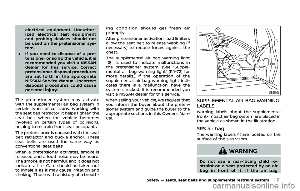
SSS1016
SUPPLEMENTAL AIR BAG WARNING
LABELS
Warning labels about the supplemental
front-impact air bag system are placed in
the vehicle as shown in the illustration.
SRS air bag
The warning labelsare located on the
surface of the sun visors.
WARNING
Do not use a rear-facing child re-
straint on a seat protected by an air
bag in front of it. If the air bag
Safety — seats, seat belts and supplemental restraint system1-71
Page 92 of 536
1-72Safety — seats, seat belts and supplemental restraint system
deploys, it may cause serious injury
or death.
SPA1097
SUPPLEMENTAL AIR BAG WARNING
LIGHT
The supplemental air bag warning light,
displayingin the instrument panel,
monitors the circuits for the air bag
systems, pretensioners and all related
wiring.
When the ignition switch is in the ON
position, the supplemental air bag warn-
ing light illuminates for about 7 seconds
and then turns off. This means the system
is operational.
If any of the following conditions occur,
the air bag and/or pretensioner systems
need servicing: .
The supplemental air bag warning
light remains on after approximately
7 seconds.
. The supplemental air bag warning
light flashes intermittently.
. The supplemental air bag warning
light does not come on at all.
Under these conditions, the air bag and/
or pretensioner systems may not operate
properly. They must be checked and
repaired. It is recommended you visit a
NISSAN dealer for this service.
WARNING
If the supplemental air bag warning
light is on, it could mean that the
front air bag, side air bag, curtain air
bag and/or pretensioner systems
will not operate in an accident. To
help avoid injury to yourself or
others, have your vehicle checked
as soon as possible. It is recom-
mended you visit a NISSAN dealer
for this service.
Page 98 of 536
2-4Instruments and controls
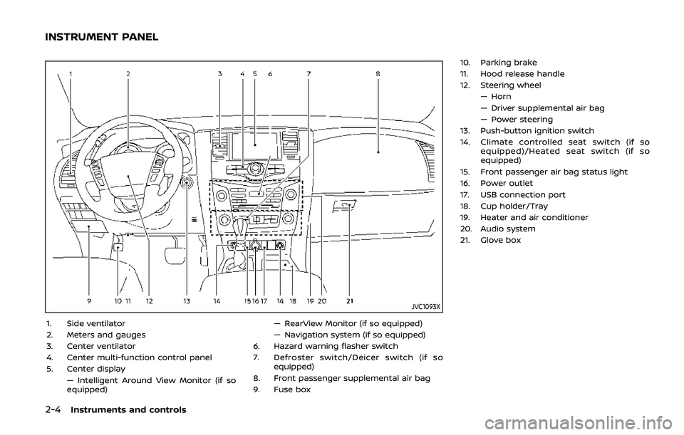
JVC1093X
1. Side ventilator
2. Meters and gauges
3. Center ventilator
4. Center multi-function control panel
5. Center display— Intelligent Around View Monitor (if so
equipped) — RearView Monitor (if so equipped)
— Navigation system (if so equipped)
6. Hazard warning flasher switch
7. Defroster switch/Deicer switch (if so equipped)
8. Front passenger supplemental air bag
9. Fuse box 10. Parking brake
11. Hood release handle
12. Steering wheel
— Horn
— Driver supplemental air bag
— Power steering
13. Push-button ignition switch
14. Climate controlled seat switch (if so equipped)/Heated seat switch (if so
equipped)
15. Front passenger air bag status light
16. Power outlet
17. USB connection port
18. Cup holder/Tray
19. Heater and air conditioner
20. Audio system
21. Glove box
INSTRUMENT PANEL
Page 101 of 536
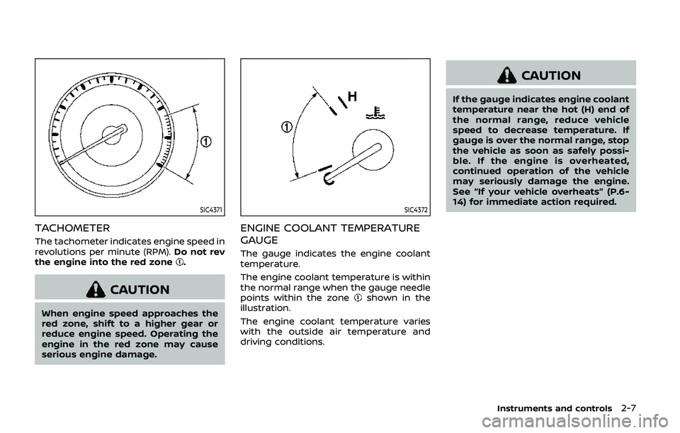
SIC4371
TACHOMETER
The tachometer indicates engine speed in
revolutions per minute (RPM).Do not rev
the engine into the red zone
.
CAUTION
When engine speed approaches the
red zone, shift to a higher gear or
reduce engine speed. Operating the
engine in the red zone may cause
serious engine damage.
SIC4372
ENGINE COOLANT TEMPERATURE
GAUGE
The gauge indicates the engine coolant
temperature.
The engine coolant temperature is within
the normal range when the gauge needle
points within the zone
shown in the
illustration.
The engine coolant temperature varies
with the outside air temperature and
driving conditions.
CAUTION
If the gauge indicates engine coolant
temperature near the hot (H) end of
the normal range, reduce vehicle
speed to decrease temperature. If
gauge is over the normal range, stop
the vehicle as soon as safely possi-
ble. If the engine is overheated,
continued operation of the vehicle
may seriously damage the engine.
See “If your vehicle overheats” (P.6-
14) for immediate action required.
Instruments and controls2-7
Page 107 of 536
WARNING
.Your brake system may not be
working properly if the warning
light is on. Driving could be dan-
gerous. If you judge it to be safe,
drive carefully to the nearest
service station for repairs. Other-
wise, have your vehicle towed
because driving it could be dan-
gerous.
. Pressing the brake pedal with the
engine stopped and/or low brake
fluid level may increase your
stopping distance and braking
will require greater pedal effort
as well as pedal travel.
. If the brake fluid level is below the
minimum or MIN mark on the
brake fluid reservoir, do not drive
until the brake system has been
checked. It is recommended you
visit a NISSAN dealer for this
service.
Charge warning light
If the light comes on while the engine is
running, it may indicate the charging
system is not functioning properly. Turn
the engine off and check the alternator
belt. If the belt is loose, broken, missing or
if the light remains on, have your vehicle
serviced immediately. It is recommended
you visit a NISSAN dealer for this service.
CAUTION
Do not continue driving if the alter-
nator belt is loose, broken or miss-
ing.
Intelligent Distance Control (I-
DC) system warning light (orange; if
so equipped)
This light comes on if there is a malfunc-
tion in the Intelligent Distance Control (I-
DC) system.
If the warning light illuminates, park the
vehicle in a safe place. Turn the engine off,
restart the engine, resume driving and
turn on the I-DC system again.
If it is not possible to turn on the system
or the warning light stays on, it may indicate that the system is malfunction-
ing. Although the vehicle is still drive-
able under normal conditions, have the
vehicle checked. It is recommended you
visit a NISSAN dealer for this service.
See “Intelligent Distance Control (I-DC)”
(P.5-89).
Engine oil pressure warning
light
This light warns of low engine oil pres-
sure. If the light flickers or comes on
during normal driving, pull off the road in
a safe area, stop the engine immediately
and call a NISSAN dealer or other author-
ized repair shop.
The engine oil pressure warning light is
not designed to indicate a low oil level.
Use the dipstick to check the oil level.
(See “Engine oil” (P.8-6).)
CAUTION
Running the engine with the engine
oil pressure warning light on could
cause serious damage to the engine
almost immediately. Such damage is
not covered by warranty. Turn off the
engine as soon as it is safe to do so.
Instruments and controls2-13
Page 111 of 536
seconds after the ignition switch is placed
in the ON position, the system does not
activate the warning light for the front
passenger.
See “Seat belts” (P.1-20) for precautions on
seat belt usage.
Supplemental air bag warning
light
After placing the ignition switch in the ON
position, the supplemental air bag warn-
ing light will illuminate. The supplemental
air bag warning light will turn off after
about 7 seconds if the air bag and/or
pretensioner systems are operational.
If any of the following conditions occur,
the air bag and/or pretensioner systems
needs servicing.
. The supplemental air bag warning
light remains on after approximately
7 seconds.
. The supplemental air bag warning
light flashes intermittently.
. The supplemental air bag warning
light does not come on at all.
It is recommended you visit a NISSAN
dealer for these services.
Unless checked and repaired, the supple-
mental restraint system (air bag system)
and/or the pretensioners may not func- tion properly.
For additional information, see “Supple-
mental restraint system” (P.1-55).
WARNING
If the supplemental air bag warning
light is on, it could mean that the
front air bag, side air bag, curtain air
bag systems and/or pretensioner
systems will not operate in an acci-
dent. To help avoid injury to yourself
or others, have your vehicle checked.
It is recommended you visit a NISSAN
dealer for this service.
Vehicle Dynamic Control (VDC)
warning light
When the ignition switch is in the ON
position, the Vehicle Dynamic Control
(VDC) warning light illuminates and then
turns off.
The light will blink when the VDC system
or the traction control system is operat-
ing, thus alerting the driver that the
vehicle is nearing its traction limits. The
road surface may be slippery.
When the VDC warning light illuminates
when the VDC system is turned on, this light alerts the driver to the fact that the
VDC system’s fail-safe mode is operating,
for example the VDC or hill start assist
system may not be functioning properly.
Have the system checked. It is recom-
mended you visit a NISSAN dealer for this
service. If a malfunction occurs in the
system, the VDC system function will be
canceled but the vehicle is still driveable.
For additional information, see “Vehicle
Dynamic Control (VDC) system” (P.5-138).
INDICATOR LIGHTS
Automatic Transmission (AT)
position indicator light
When the ignition switch is placed in the
ON position, the indicator shows the shift
lever position.
In the manual shift mode, when the
transmission does not shift to the se-
lected gear due to a transmission protec-
tion mode, the AT position indicator light
will blink and a buzzer will sound.
See “Automatic transmission” (P.5-18) for
further details.
Instruments and controls2-17
Page 146 of 536
2-52Instruments and controls
CAUTION
.Use power outlet with the engine
running to avoid discharging the
vehicle battery.
. Avoid using power outlet when
the air conditioner, headlights or
rear window defroster is on.
. Before inserting or disconnecting
a plug, be sure the electrical
accessory being used is turned
OFF.
. When not in use, be sure to close
the cap. Do not allow water or any
liquid to contact the outlet.
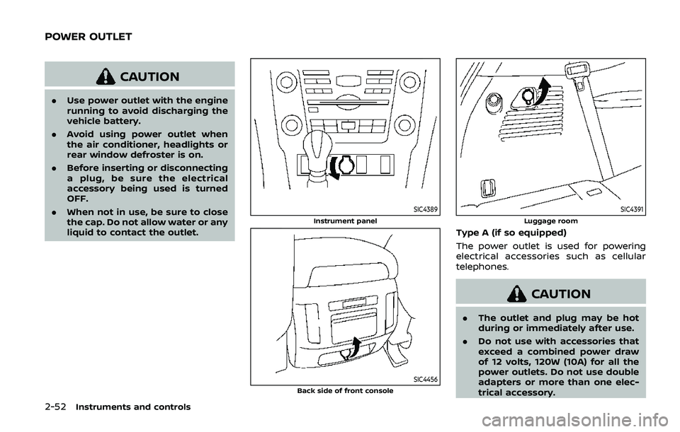
SIC4389
Instrument panel
SIC4456Back side of front console
SIC4391
Luggage room
Type A (if so equipped)
The power outlet is used for powering
electrical accessories such as cellular
telephones.
CAUTION
.The outlet and plug may be hot
during or immediately after use.
. Do not use with accessories that
exceed a combined power draw
of 12 volts, 120W (10A) for all the
power outlets. Do not use double
adapters or more than one elec-
trical accessory.
POWER OUTLET
Page 162 of 536
2-68Instruments and controls
matically when the auto reverse function
activates due to a malfunction, push and
hold the switch to the CLOSE
position.
Depending on the environment or driv-
ing conditions, the auto reverse func-
tion may be activated if an impact or
load similar to something being caught
in the moonroof occurs.
If the moonroof does not operate
If the moonroof does not operate prop-
erly, perform the following procedure to
initialize the moonroof operation system.
1. If the moonroof is open, close it fully by repeatedly pushing the moonroof
switch to the CLOSE
position.
2. Push and hold the switch to the CLOSE
position.
3. Release the moonroof switch after the moonroof moves slightly up and
down.
4. Push and hold the switch to the OPEN
position to fully tilt the moonroof
down.
5. Check if the moonroof switch oper- ates normally.
If the moonroof does not operate prop-
erly after performing the procedure
above, have your moonroof checked and
repaired. It is recommended you visit a
NISSAN dealer for this service.
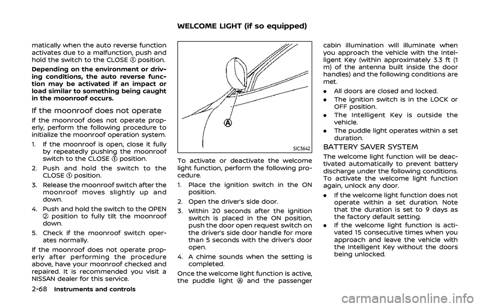
SIC3642
To activate or deactivate the welcome
light function, perform the following pro-
cedure.
1. Place the ignition switch in the ON position.
2. Open the driver’s side door.
3. Within 20 seconds after the ignition switch is placed in the ON position,
push the door open request switch on
the driver’s side door handle for more
than 5 seconds with the driver’s door
open.
4. A chime sounds when the setting is completed.
Once the welcome light function is active,
the puddle light
and the passenger cabin illumination will illuminate when
you approach the vehicle with the Intel-
ligent Key (within approximately 3.3 ft (1
m) of the antenna built inside the door
handles) and the following conditions are
met.
.
All doors are closed and locked.
. The ignition switch is in the LOCK or
OFF position.
. The Intelligent Key is outside the
vehicle.
. The puddle light operates within a set
duration.
BATTERY SAVER SYSTEM
The welcome light function will be deac-
tivated automatically to prevent battery
discharge under the following conditions.
To activate the welcome light function
again, unlock any door.
.If the welcome light function does not
operate within a set duration. Note
that the duration is set to 9 days as
the factory default setting.
. If the welcome light function is acti-
vated 15 consecutive times when you
approach and leave the vehicle with
the Intelligent Key without the doors
being unlocked.
WELCOME LIGHT (if so equipped)
Page 181 of 536
WARNING
.Radio waves could adversely af-
fect electric medical equipment.
Those who use a pacemaker
should contact the electric med-
ical equipment manufacturer for
the possible influences before
use.
. The Intelligent Key transmits
radio waves when the buttons
are pushed. The FAA advises that
the radio waves may affect air-
craft navigation and communica-
tion systems. Do not operate the
Intelligent Key while on an air-
plane. Make sure the buttons are
not operated unintentionally
when the unit is stored during a
flight.
The Intelligent Key system can operate all
the door locks using the remote control-
ler function or pushing the request switch
on the vehicle without taking the key out
from a pocket or purse. The operating
environment and/or conditions may af-
fect the Intelligent Key system operation.
Be sure to read the following before using
the Intelligent Key system.
CAUTION
. Be sure to carry the Intelligent
Key with you when operating the
vehicle.
. Never leave the Intelligent Key in
the vehicle when you leave the
vehicle.
The Intelligent Key is always communi-
cating with the vehicle as it receives radio
waves. The Intelligent Key system trans-
mits weak radio waves. Environmental
conditions may interfere with the opera-
tion of the Intelligent Key system under
the following operating conditions.
. When operating near a location where
strong radio waves are transmitted,
such as a TV tower, power station and
broadcasting station.
. When in possession of wireless equip-
ment, such as a cellular telephone,
transceiver, and CB radio.
. When the Intelligent Key is in contact
with or covered by metallic materials.
. When any type of radio wave remote
control is used nearby.
. When the Intelligent Key is placed near
an electric appliance such as a perso-
nal computer. .
When the vehicle is parked near a
parking meter.
In such cases, correct the operating
conditions before using the Intelligent
Key function or use the mechanical key.
Although the life of the battery varies
depending on the operating conditions,
the battery’s life is approximately 2 years.
If the battery is discharged, replace it with
a new one.
Since the Intelligent Key is continuously
receiving radio waves, if the key is left
near equipment which transmits strong
radio waves, such as signals from a TV
and personal computer, the battery life
may become shorter.
For information regarding replacement of
a battery, see “Intelligent Key battery
replacement” (P.8-21).
As many as 4 Intelligent Keys can be
registered and used with one vehicle. For
information about the purchase and use
of additional Intelligent Keys, contact a
NISSAN dealer.
CAUTION
. Do not allow the Intelligent Key,
which contains electrical compo-
nents, to come into contact with
water or salt water. This could
Pre-driving checks and adjustments3-7
INTELLIGENT KEY SYSTEM
Page 189 of 536
WARNING
The Intelligent Key transmits radio
waves when the buttons are pushed.
The FAA advises that radio waves
may affect aircraft navigation and
communication systems. Do not op-
erate the Intelligent Key while on an
airplane. Make sure the buttons are
not operated unintentionally when
the unit is stored for a flight.
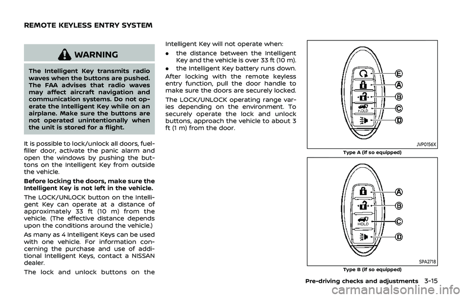
It is possible to lock/unlock all doors, fuel-
filler door, activate the panic alarm and
open the windows by pushing the but-
tons on the Intelligent Key from outside
the vehicle.
Before locking the doors, make sure the
Intelligent Key is not left in the vehicle.
The LOCK/UNLOCK button on the Intelli-
gent Key can operate at a distance of
approximately 33 ft (10 m) from the
vehicle. (The effective distance depends
upon the conditions around the vehicle.)
As many as 4 Intelligent Keys can be used
with one vehicle. For information con-
cerning the purchase and use of addi-
tional Intelligent Keys, contact a NISSAN
dealer.
The lock and unlock buttons on the Intelligent Key will not operate when:
.
the distance between the Intelligent
Key and the vehicle is over 33 ft (10 m).
. the Intelligent Key battery runs down.
After locking with the remote keyless
entry function, pull the door handle to
make sure the doors are securely locked.
The LOCK/UNLOCK operating range var-
ies depending on the environment. To
securely operate the lock and unlock
buttons, approach the vehicle to about 3
ft (1 m) from the door.
JVP0156X
Type A (if so equipped)
SPA2718Type B (if so equipped)
Pre-driving checks and adjustments3-15
REMOTE KEYLESS ENTRY SYSTEM