NISSAN FRONTIER 1999 D22 / 1.G Manual Online
Manufacturer: NISSAN, Model Year: 1999, Model line: FRONTIER, Model: NISSAN FRONTIER 1999 D22 / 1.GPages: 247, PDF Size: 1.89 MB
Page 81 of 247
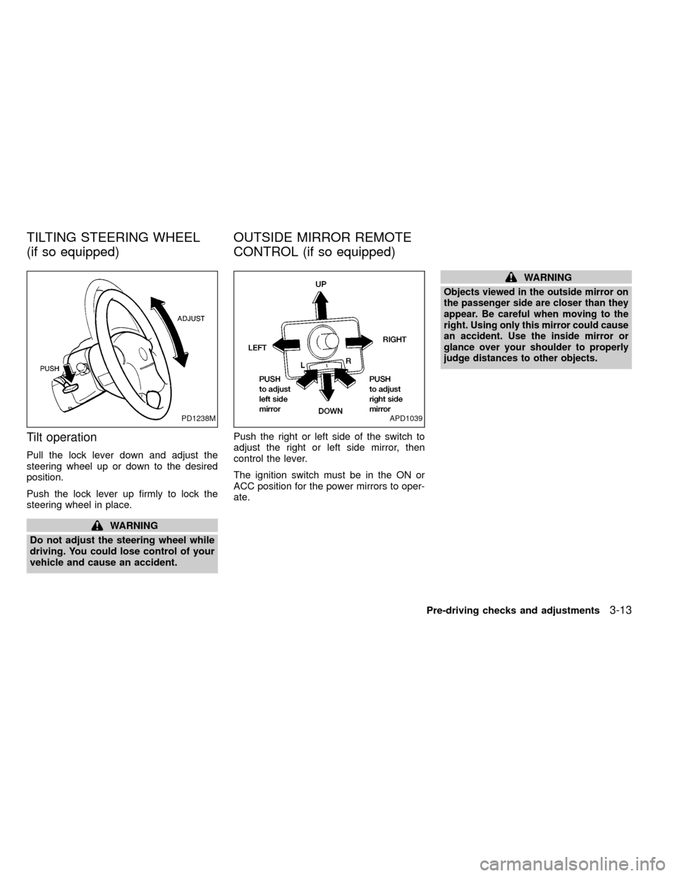
Tilt operation
Pull the lock lever down and adjust the
steering wheel up or down to the desired
position.
Push the lock lever up firmly to lock the
steering wheel in place.
WARNING
Do not adjust the steering wheel while
driving. You could lose control of your
vehicle and cause an accident.Push the right or left side of the switch to
adjust the right or left side mirror, then
control the lever.
The ignition switch must be in the ON or
ACC position for the power mirrors to oper-
ate.
WARNING
Objects viewed in the outside mirror on
the passenger side are closer than they
appear. Be careful when moving to the
right. Using only this mirror could cause
an accident. Use the inside mirror or
glance over your shoulder to properly
judge distances to other objects.
PD1238MAPD1039
TILTING STEERING WHEEL
(if so equipped)OUTSIDE MIRROR REMOTE
CONTROL (if so equipped)
Pre-driving checks and adjustments3-13
ZX
Page 82 of 247
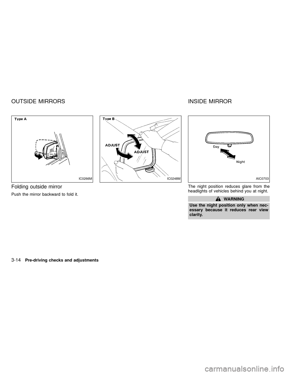
Folding outside mirror
Push the mirror backward to fold it.The night position reduces glare from the
headlights of vehicles behind you at night.WARNING
Use the night position only when nec-
essary because it reduces rear view
clarity.
IC0266MIC0248MAIC0703
OUTSIDE MIRRORS INSIDE MIRROR
3-14Pre-driving checks and adjustments
ZX
Page 83 of 247
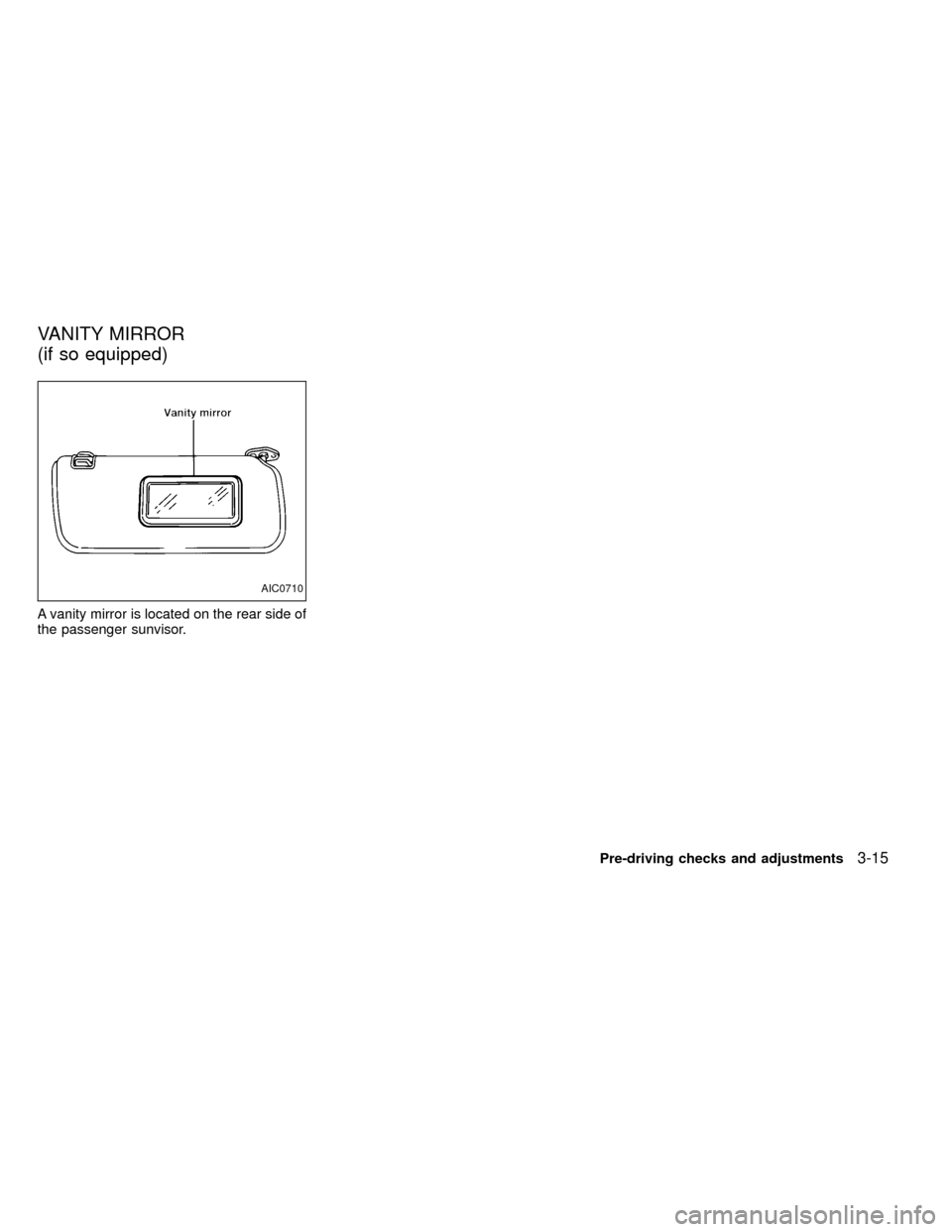
A vanity mirror is located on the rear side of
the passenger sunvisor.
AIC0710
VANITY MIRROR
(if so equipped)
Pre-driving checks and adjustments3-15
ZX
Page 84 of 247

MEMO
3-16Pre-driving checks and adjustments
ZX
Page 85 of 247

4Heater, air conditioner and audio systems
Ventilators ..............................................................4-2
Heater and air conditioner ......................................4-3
Controls ..................................................................4-3
Heater operation ....................................................4-4
Air conditioner operation (if so equipped) ..............4-5
Air flow charts.........................................................4-7
AM-FM radio with cassette player........................ 4-11
Radio operation .................................................... 4-11
Cassette tape operation .......................................4-14AM-FM radio with cassette player, compact
disc player and sub-woofer (if so equipped) ........4-16
Radio operation ....................................................4-16
Cassette tape operation .......................................4-20
Compact disc (CD) player operation ....................4-21
Antenna ................................................................4-23
CB radio or car phone..........................................4-23
ZX
Page 86 of 247
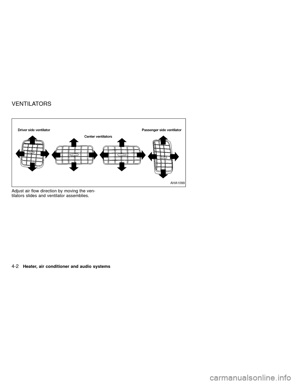
Adjust air flow direction by moving the ven-
tilators slides and ventilator assemblies.
AHA1099
VENTILATORS
4-2Heater, air conditioner and audio systems
ZX
Page 87 of 247
WARNING
IThe air conditioner cooling function
operates only when the engine is
running.
IDo not leave children, unreliable
adults, or pets alone in your vehicle.
On hot sunny days, temperatures in
a closed vehicle could quickly be-
come high enough to cause severe
or possibly fatal injuries to people or
animals.
IDo not use the recirculation mode
for long periods as it may cause theinterior air to become stale and the
windows to fog up.
IPositioning of the heating or air con-
ditioning controls should not be
done while driving, so that full atten-
tion may be given to the driving
operation.
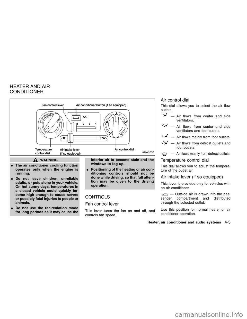
CONTROLS
Fan control lever
This lever turns the fan on and off, and
controls fan speed.
Air control dial
This dial allows you to select the air flow
outlets.
Ð Air flows from center and side
ventilators.
Ð Air flows from center and side
ventilators and foot outlets.
Ð Air flows mainly from foot outlets.
Ð Air flows from defrost outlets and
foot outlets.
ÐAir flows mainly from defrost outlets.
Temperature control dial
This dial allows you to adjust the tempera-
ture of the outlet air.
Air intake lever (if so equipped)
This lever is provided only for vehicles with
an air conditioner.
Ð Outside air is drawn into the pas-
senger compartment and distributed
through the selected outlet.
Use this position for normal heater or air
conditioner operation.
AHA1035
HEATER AND AIR
CONDITIONER
Heater, air conditioner and audio systems4-3
ZX
Page 88 of 247

Ð Interior air is recirculated inside the
vehicle.
Move the air intake lever to the
position:
Iwhen driving on a dusty road.
Ito prevent traffic fumes from entering the
passenger compartment.
Ifor maximum cooling when using the air
conditioner.
Air conditioner switch
(if so equipped)
This switch is present only in vehicles
equipped with an air conditioner.
Start the engine, push the air conditioner
switch and move the fan control lever to the
desired speed. The indicator light comes on
when the air conditioner is operating.
HEATER OPERATION
Heating
This mode directs heated air from the foot
outlets. A small amount of air is also di-
rected from the defrost outlets.
1. Move the air intake lever to the
position for normal heating.
2. Turn the air control dial to theposition.
3. Move the fan control lever to the desired
speed.
4. Turn the temperature control dial clock-
wise until it stops or to the desired posi-
tion.
Ventilation
This mode directs outside air from the side
and center ventilators.
1. Move the air intake lever to the
position.
2. Turn the air control dial to the
position.
3. Move the fan control lever to the desired
speed.
4. Turn the temperature control dial to the
desired position.
Defrosting/defogging
This mode directs heated air from the
defrosting/defogging outlets.
1. Move the air intake lever to the
position.2. Turn the air control dial to the
position.
3. Move the fan control lever to the desired
speed.
4. Turn the temperature control dial clock-
wise until it stops or to the desired posi-
tion.
If it is difficult to defog the windshield,
push the air conditioner switch (if so
equipped) on. This dehumidifies the air,
which helps defog the windshield.
To quickly remove ice or fog from the
windows, move the fan control lever to 4
and the temperature control dial to the
full clockwise position.
Bi-level heating/cooling
This mode directs air from the side and
center ventilators and from the foot outlets.
1. Move the air intake lever to the
position.
2. Turn the air control dial to the
position.
3. Move the fan control lever to the desired
speed.
4-4Heater, air conditioner and audio systems
ZX
Page 89 of 247

4. Turn the temperature control dial to the
desired position.
Heating and defrosting/defogging
This mode directs heated air from the foot
outlets and defrosts/defogs the windshield.
1. Move the air intake lever to the
position.
2. Turn the air control dial to the
position.
3. Move the fan control lever to the desired
speed.
4. Turn the temperature control dial clock-
wise until it stops or to the desired posi-
tion.
If it is difficult to defog the windshield,
push the air conditioner switch (if so
equipped) on. This dehumidifies the air,
which helps defog the windshield.
Operating tips
Clear snow and ice from the wiper blades
and air inlet in front of the windshield. This
improves heater and defroster operation.
AIR CONDITIONER OPERATION
(if so equipped)
Start the engine, move the fan control lever
to the desired (one to four) position, and
push in the air conditioner switch to activate
the air conditioner. When the air conditioner
is on, cooling and dehumidifying functions
are added to the heater operation.
The air conditioner cooling function op-
erates only when the engine is running.
Cooling
This mode directs cool, dehumudified air
from the side and center ventilators.
1. Move the air intake lever to the
position.
2. Turn the air control dial to the
position.
3. Move the fan control lever to the desired
position.
4. Push in the air conditioner switch. The
indicator light comes on.
5. Turn the temperature control dial to the
desired position.
IFor quick cooling when the outside tem-
perature is high, move the air intake leverto the
position. Be sure to return
the air intake lever to theposition
for normal cooling.
Dehumidified heating
This mode directs heated, dehumidfied air
from the defrosting/defogging outlets.
1. Move the air intake lever to the
position.
2. Turn the air control dial to the
position.
3. Move the fan control lever to the desired
position.
4. Push in the air conditioner switch. The
indicator light comes on.
5. Turn the temperature control dial clock-
wise until it stops or to the desired posi-
tion.
Dehumidified defrosting/defogging
This mode directs heated, dehumidified air
from the defrosting/ defogging outlets.
1. Turn the air intake lever to the
po-
sition.
Heater, air conditioner and audio systems
4-5
ZX
Page 90 of 247

2. Move the air control dial to the,
, or the position in between.
3. Move the fan control lever to the desired
position.
4. Push in the air conditioner switch. The
indicator light comes on.
5. Turn the temperature control dial to the
desired position.
Operating tips
IKeep windows and sunroof closed while
operating the air conditioner.
IAfter parking in the sun, drive for two or
three minutes with the windows open to
vent hot air from the passenger compart-
ment. Then, close the windows. This
allows the air conditioner to cool the
interior more quickly.
IThe air conditioning system should be
operated for about ten minutes at least
once a month, especially in winter. This
helps prevent damage to the system due
to lack of lubrication.
IIf the coolant temperature gauge ex-
ceeds the (hot) position, turn the air
conditioner off. Have your vehicle in-spected by a NISSAN dealer. See ``If
your vehicle overheats'' in the ``In case of
emergency'' section for additional infor-
mation.
4-6Heater, air conditioner and audio systems
ZX