clock NISSAN FRONTIER 1999 D22 / 1.G Owners Manual
[x] Cancel search | Manufacturer: NISSAN, Model Year: 1999, Model line: FRONTIER, Model: NISSAN FRONTIER 1999 D22 / 1.GPages: 247, PDF Size: 1.89 MB
Page 21 of 247
turn the passenger supplemental air bag
OFF.
The ON/OFF switch should ONLY
be used
to turn the passenger supplemental air bag
OFF when the following government criteria
exists:
IInfants (less than 1 year old) in rear
facing child restraints MUST
be placed
in the front passenger seat.
IChildren ages 1-12 years MUST
be
placed in the front passenger seat.
I
The passenger has a medical condition
which, according to a physician, causes
the air bag to pose a special risk and
makes the potential harm from the air-
bag greater than the potential harm
from turning off the air bag.
Seat belts and child restraints should al-
ways be properly used. See ªPrecautions
on seat belt usageº and ªChild restraintsº
later in this section for details.
To turn the passenger supplemental air bag
OFF, insert the ignition key in the passenger
supplemental air bag ON/OFF switch and
turn the switch clockwise to the OFF position.
Then remove the key. When the ignition is
turned to the ON or START position thepassenger air bag OFF indicator light will
illuminate to indicate the air bag is OFF. To
turn the passenger supplemental air bag ON,
insert the ignition key in the passenger
supplemental air bag ON/OFF switch and
turn the switch counter clockwise to the ON
position. Then remove the key. When the
ignition is turned to the ON or START posi-
tion the passenger air bag OFF indicator light
will illuminate for 7 seconds to indicate the
system is working properly and then go out to
indicate that the passenger supplemental air
bag is ON.
When the switch is turned to the ON posi-
tion, the passenger supplemental air bag is
enabled and could inflate in a frontal colli-
sion. When the switch is turned to the OFF
position, the passenger supplemental air
bag is disabled and will not inflate in a
frontal collision. The passenger supplemen-
tal air bag OFF indicator light on the instru-
ment panel illuminates when the passenger
supplemental air bag ON/OFF switch is
turned to the OFF position. The driver's side
supplemental air bag always remains en-
abled and is not affected by the passenger
supplemental air bag ON/OFF switch.
The passenger supplemental air bag light,displaying OFF in the center of the instru-
ment panel, monitors the position of the
passenger supplemental air bag ON/OFF
switch. When the ignition key is in the ON or
START position, the light illuminates for
about 7 seconds and then turns off if the air
bag is ON/OFF switch is in the ON position,
or stays on if the passenger supplemental
air bag ON/OFF switch is in the OFF
position.
WARNING
IDo not switch the airbag OFF unless
you meet the federal government cri-
teria outlined previously. This ve-
hicle is equipped with seat belts with
a²load limiter²feature. The seat
belts are designed to work with the
air bags to reduce the risk of injury
in a collision. The seat belts are
designed to release additional belt
webbing during some collisions to
reduce the concentration of force on
the occupant's chest area. In a colli-
sion with the airbag turned OFF, the
seat belt may allow the occupant
enough forward movement to incur
serious or fatal injuries.
Seats, restraints and supplemental air bag systems
1-15
ZX
Page 64 of 247
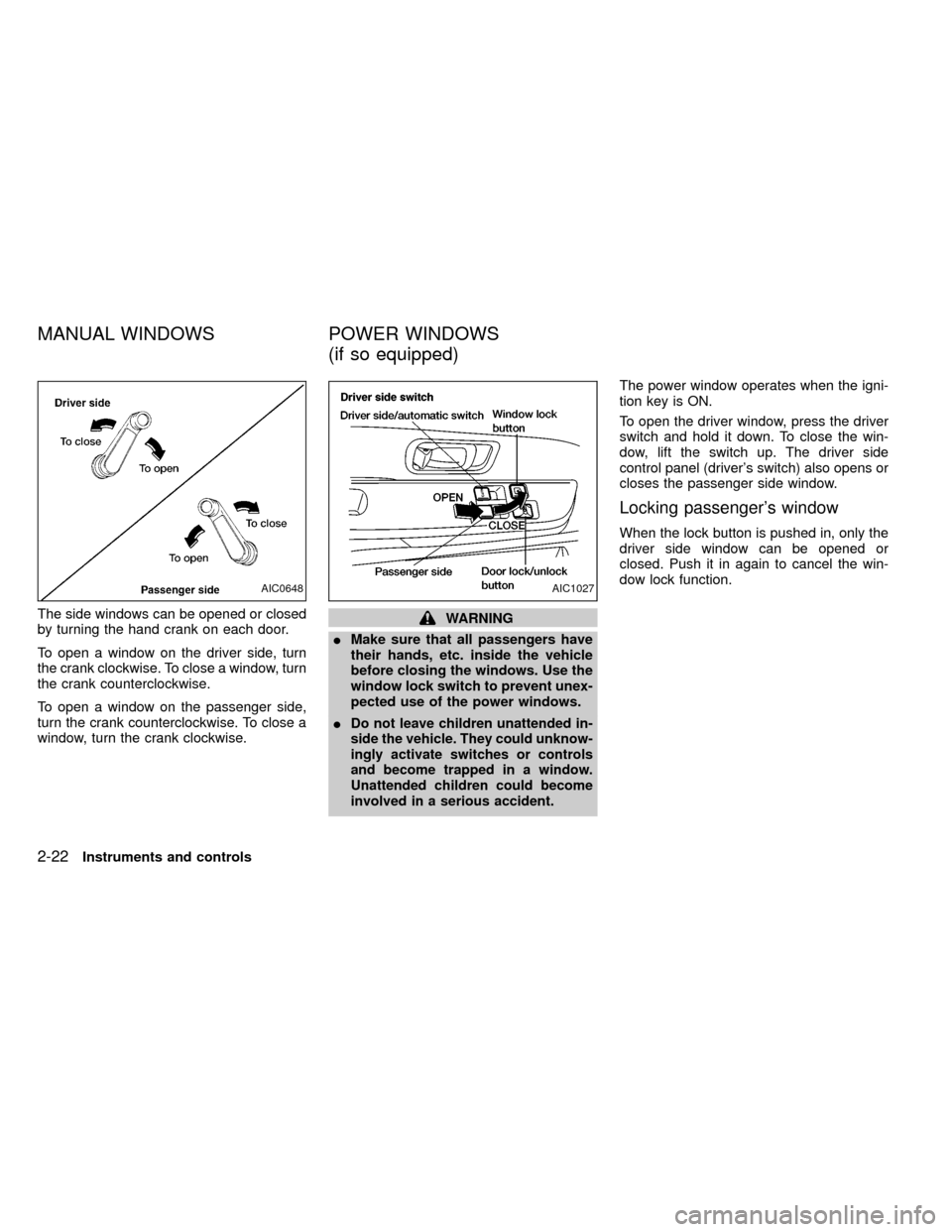
The side windows can be opened or closed
by turning the hand crank on each door.
To open a window on the driver side, turn
the crank clockwise. To close a window, turn
the crank counterclockwise.
To open a window on the passenger side,
turn the crank counterclockwise. To close a
window, turn the crank clockwise.WARNING
IMake sure that all passengers have
their hands, etc. inside the vehicle
before closing the windows. Use the
window lock switch to prevent unex-
pected use of the power windows.
I
Do not leave children unattended in-
side the vehicle. They could unknow-
ingly activate switches or controls
and become trapped in a window.
Unattended children could become
involved in a serious accident.
The power window operates when the igni-
tion key is ON.
To open the driver window, press the driver
switch and hold it down. To close the win-
dow, lift the switch up. The driver side
control panel (driver's switch) also opens or
closes the passenger side window.
Locking passenger's window
When the lock button is pushed in, only the
driver side window can be opened or
closed. Push it in again to cancel the win-
dow lock function.
AIC0648AIC1027
MANUAL WINDOWS POWER WINDOWS
(if so equipped)
2-22Instruments and controls
ZX
Page 67 of 247
WARNING
Do not remove or install the sun shade
while driving so that full attention may
be given to the driving operation.
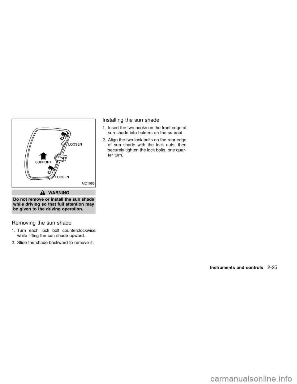
Removing the sun shade
1. Turn each lock bolt counterclockwise
while lifting the sun shade upward.
2. Slide the shade backward to remove it.
Installing the sun shade
1. Insert the two hooks on the front edge of
sun shade into holders on the sunroof.
2. Align the two lock bolts on the rear edge
of sun shade with the lock nuts, then
securely tighten the lock bolts, one quar-
ter turn.
AIC1083
Instruments and controls2-25
ZX
Page 77 of 247
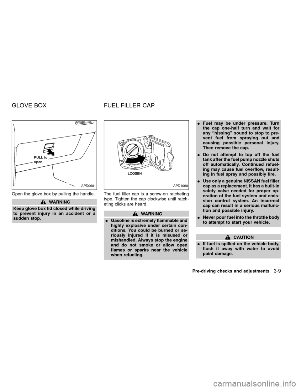
Open the glove box by pulling the handle.
WARNING
Keep glove box lid closed while driving
to prevent injury in an accident or a
sudden stop.The fuel filler cap is a screw-on ratcheting
type. Tighten the cap clockwise until ratch-
eting clicks are heard.
WARNING
IGasoline is extremely flammable and
highly explosive under certain con-
ditions. You could be burned or se-
riously injured if it is misused or
mishandled. Always stop the engine
and do not smoke or allow open
flames or sparks near the vehicle
when refueling.IFuel may be under pressure. Turn
the cap one-half turn and wait for
any ``hissing'' sound to stop to pre-
vent fuel from spraying out and
causing possible personal injury.
Then remove the cap.
IDo not attempt to top off the fuel
tank after the fuel pump nozzle shuts
off automatically. Continued refuel-
ing may cause fuel overflow, result-
ing in fuel spray and possibly fire.
IUse only a genuine NISSAN fuel filler
cap as a replacement. It has a built-in
safety valve needed for proper op-
eration of the fuel system and emis-
sion control system. An incorrect
cap can result in a serious malfunc-
tion and possible injury.
INever pour fuel into the throttle body
to attempt to start your vehicle.
CAUTION
IIf fuel is spilled on the vehicle body,
flush it away with water to avoid
paint damage.
APD0601APD1060
GLOVE BOX FUEL FILLER CAP
Pre-driving checks and adjustments3-9
ZX
Page 88 of 247

Ð Interior air is recirculated inside the
vehicle.
Move the air intake lever to the
position:
Iwhen driving on a dusty road.
Ito prevent traffic fumes from entering the
passenger compartment.
Ifor maximum cooling when using the air
conditioner.
Air conditioner switch
(if so equipped)
This switch is present only in vehicles
equipped with an air conditioner.
Start the engine, push the air conditioner
switch and move the fan control lever to the
desired speed. The indicator light comes on
when the air conditioner is operating.
HEATER OPERATION
Heating
This mode directs heated air from the foot
outlets. A small amount of air is also di-
rected from the defrost outlets.
1. Move the air intake lever to the
position for normal heating.
2. Turn the air control dial to theposition.
3. Move the fan control lever to the desired
speed.
4. Turn the temperature control dial clock-
wise until it stops or to the desired posi-
tion.
Ventilation
This mode directs outside air from the side
and center ventilators.
1. Move the air intake lever to the
position.
2. Turn the air control dial to the
position.
3. Move the fan control lever to the desired
speed.
4. Turn the temperature control dial to the
desired position.
Defrosting/defogging
This mode directs heated air from the
defrosting/defogging outlets.
1. Move the air intake lever to the
position.2. Turn the air control dial to the
position.
3. Move the fan control lever to the desired
speed.
4. Turn the temperature control dial clock-
wise until it stops or to the desired posi-
tion.
If it is difficult to defog the windshield,
push the air conditioner switch (if so
equipped) on. This dehumidifies the air,
which helps defog the windshield.
To quickly remove ice or fog from the
windows, move the fan control lever to 4
and the temperature control dial to the
full clockwise position.
Bi-level heating/cooling
This mode directs air from the side and
center ventilators and from the foot outlets.
1. Move the air intake lever to the
position.
2. Turn the air control dial to the
position.
3. Move the fan control lever to the desired
speed.
4-4Heater, air conditioner and audio systems
ZX
Page 89 of 247

4. Turn the temperature control dial to the
desired position.
Heating and defrosting/defogging
This mode directs heated air from the foot
outlets and defrosts/defogs the windshield.
1. Move the air intake lever to the
position.
2. Turn the air control dial to the
position.
3. Move the fan control lever to the desired
speed.
4. Turn the temperature control dial clock-
wise until it stops or to the desired posi-
tion.
If it is difficult to defog the windshield,
push the air conditioner switch (if so
equipped) on. This dehumidifies the air,
which helps defog the windshield.
Operating tips
Clear snow and ice from the wiper blades
and air inlet in front of the windshield. This
improves heater and defroster operation.
AIR CONDITIONER OPERATION
(if so equipped)
Start the engine, move the fan control lever
to the desired (one to four) position, and
push in the air conditioner switch to activate
the air conditioner. When the air conditioner
is on, cooling and dehumidifying functions
are added to the heater operation.
The air conditioner cooling function op-
erates only when the engine is running.
Cooling
This mode directs cool, dehumudified air
from the side and center ventilators.
1. Move the air intake lever to the
position.
2. Turn the air control dial to the
position.
3. Move the fan control lever to the desired
position.
4. Push in the air conditioner switch. The
indicator light comes on.
5. Turn the temperature control dial to the
desired position.
IFor quick cooling when the outside tem-
perature is high, move the air intake leverto the
position. Be sure to return
the air intake lever to theposition
for normal cooling.
Dehumidified heating
This mode directs heated, dehumidfied air
from the defrosting/defogging outlets.
1. Move the air intake lever to the
position.
2. Turn the air control dial to the
position.
3. Move the fan control lever to the desired
position.
4. Push in the air conditioner switch. The
indicator light comes on.
5. Turn the temperature control dial clock-
wise until it stops or to the desired posi-
tion.
Dehumidified defrosting/defogging
This mode directs heated, dehumidified air
from the defrosting/ defogging outlets.
1. Turn the air intake lever to the
po-
sition.
Heater, air conditioner and audio systems
4-5
ZX
Page 96 of 247
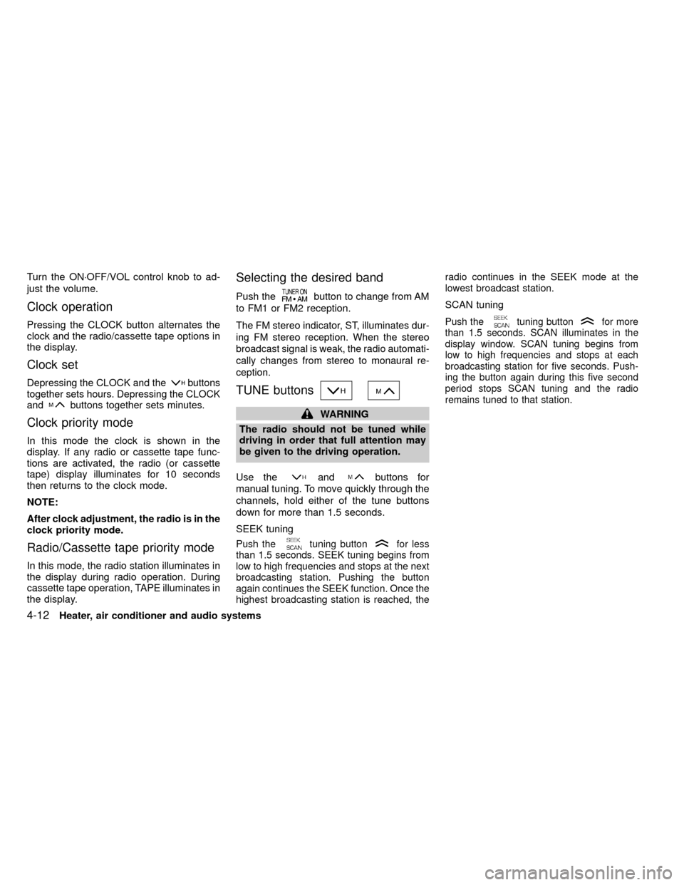
Turn the ON×OFF/VOL control knob to ad-
just the volume.
Clock operation
Pressing the CLOCK button alternates the
clock and the radio/cassette tape options in
the display.
Clock set
Depressing the CLOCK and thebuttons
together sets hours. Depressing the CLOCK
and
buttons together sets minutes.
Clock priority mode
In this mode the clock is shown in the
display. If any radio or cassette tape func-
tions are activated, the radio (or cassette
tape) display illuminates for 10 seconds
then returns to the clock mode.
NOTE:
After clock adjustment, the radio is in the
clock priority mode.
Radio/Cassette tape priority mode
In this mode, the radio station illuminates in
the display during radio operation. During
cassette tape operation, TAPE illuminates in
the display.
Selecting the desired band
Push thebutton to change from AM
to FM1 or FM2 reception.
The FM stereo indicator, ST, illuminates dur-
ing FM stereo reception. When the stereo
broadcast signal is weak, the radio automati-
cally changes from stereo to monaural re-
ception.
TUNE buttons
WARNING
The radio should not be tuned while
driving in order that full attention may
be given to the driving operation.
Use the
andbuttons for
manual tuning. To move quickly through the
channels, hold either of the tune buttons
down for more than 1.5 seconds.
SEEK tuning
Push thetuning buttonfor less
than 1.5 seconds. SEEK tuning begins from
low to high frequencies and stops at the next
broadcasting station. Pushing the button
again continues the SEEK function. Once the
highest broadcasting station is reached, theradio continues in the SEEK mode at the
lowest broadcast station.
SCAN tuning
Push thetuning buttonfor more
than 1.5 seconds. SCAN illuminates in the
display window. SCAN tuning begins from
low to high frequencies and stops at each
broadcasting station for five seconds. Push-
ing the button again during this five second
period stops SCAN tuning and the radio
remains tuned to that station.
4-12Heater, air conditioner and audio systems
ZX
Page 99 of 247

This system searches at the blank intervals
between selections. If there is a blank inter-
val within one selection or there is no inter-
val between selections, the system may not
stop in the desired or expected location.
Changing the direction of tape play
Push the(program) select button.
The moving digital squares illuminate on
either the right or left side of the display
window to indicate the side of program play.
Playing and stopping the cassette
tape
Push thebutton while the cassette
tape is playing to stop the tape. Push the
button again to play the tape.
Dolby NR (noise reduction)
Push thebutton for Dolby NR en-
coded tapes to reduce high frequency tape
noise. The
symbol illuminates in the
display.
If the display is in the clock priority mode
when the
button is pressed,and TAPE illuminate in the display
window for about 10 seconds. The clock
mode then returns to the display window.Dolby NR is manufactured under license
from Dolby Laboratories Licensing Corpora-
tion. DOLBY NR and the double-D symbol
are trademarks of Dolby Laboratories Li-
censing Corporation.
Metal or chrome tape usage
The cassette player is automatically set to
high performance play when playing a metal
or chrome cassette tape.
Ejecting the cassette tape
Push thebutton. The cassette tape
automatically comes out.
Heater, air conditioner and audio systems
4-15
ZX
Page 101 of 247
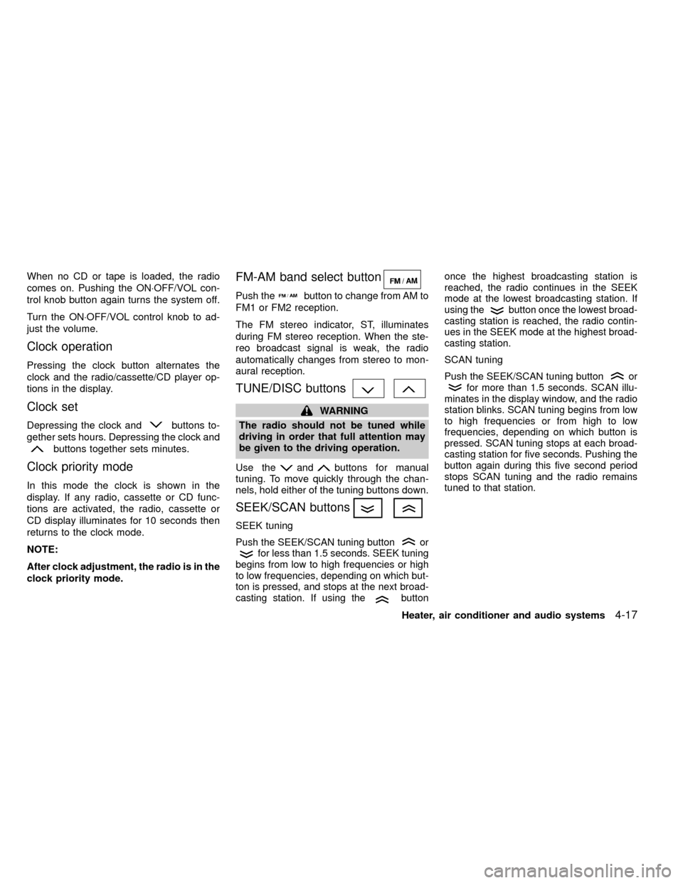
When no CD or tape is loaded, the radio
comes on. Pushing the ON×OFF/VOL con-
trol knob button again turns the system off.
Turn the ON×OFF/VOL control knob to ad-
just the volume.
Clock operation
Pressing the clock button alternates the
clock and the radio/cassette/CD player op-
tions in the display.
Clock set
Depressing the clock andbuttons to-
gether sets hours. Depressing the clock and
buttons together sets minutes.
Clock priority mode
In this mode the clock is shown in the
display. If any radio, cassette or CD func-
tions are activated, the radio, cassette or
CD display illuminates for 10 seconds then
returns to the clock mode.
NOTE:
After clock adjustment, the radio is in the
clock priority mode.
FM-AM band select button
Push thebutton to change from AM to
FM1 or FM2 reception.
The FM stereo indicator, ST, illuminates
during FM stereo reception. When the ste-
reo broadcast signal is weak, the radio
automatically changes from stereo to mon-
aural reception.
TUNE/DISC buttons
WARNING
The radio should not be tuned while
driving in order that full attention may
be given to the driving operation.
Use the
andbuttons for manual
tuning. To move quickly through the chan-
nels, hold either of the tuning buttons down.
SEEK/SCAN buttons
SEEK tuning
Push the SEEK/SCAN tuning buttonorfor less than 1.5 seconds. SEEK tuning
begins from low to high frequencies or high
to low frequencies, depending on which but-
ton is pressed, and stops at the next broad-
casting station. If using the
buttononce the highest broadcasting station is
reached, the radio continues in the SEEK
mode at the lowest broadcasting station. If
using the
button once the lowest broad-
casting station is reached, the radio contin-
ues in the SEEK mode at the highest broad-
casting station.
SCAN tuning
Push the SEEK/SCAN tuning buttonorfor more than 1.5 seconds. SCAN illu-
minates in the display window, and the radio
station blinks. SCAN tuning begins from low
to high frequencies or from high to low
frequencies, depending on which button is
pressed. SCAN tuning stops at each broad-
casting station for five seconds. Pushing the
button again during this five second period
stops SCAN tuning and the radio remains
tuned to that station.
Heater, air conditioner and audio systems4-17
ZX
Page 107 of 247
The antenna cannot be shortened, but it can
be removed. When you need to remove the
antenna, turn the antenna rod counterclock-
wise.
To install the antenna rod, turn the antenna
clockwise. Tighten the antenna rod to speci-
fication using a suitable tool such as a
open-end wrench. The antenna rod tighten-
ing specification is 3.4 - 3.6 N×m(30-32
in-lb). Do not use pliers to tighten the an-
tenna as they can leave marks on the
antenna surface. The antenna rod can not
be hand tightened to the proper specifica-
tion.
CAUTION
Always properly tighten the antenna
rod during installation or the antenna
rod may break during vehicle opera-
tion.
Microphone installed model
If equipped with a genuine NISSAN cellular
phone, your NISSAN features a non-
directional
microphone in the steering column cover, so
it is not necessary to look at or speak
directly into the microphone when calling. To
do so could detract from the driving opera-
tion and cause an accident. See the manual
for car phone operation.
Pre-wired and antenna for phone
installed model
Some models are pre-wired to accept the
genuine NISSAN cellular phone. In addition,
the same model has the phone antenna
built into the rear glass window.
When installing a CB, ham radio or car
phone in your NISSAN, be sure to observe
the following cautions, otherwise the new
equipment may adversely affect the MFI
(Multiport Fuel Injection) system and other
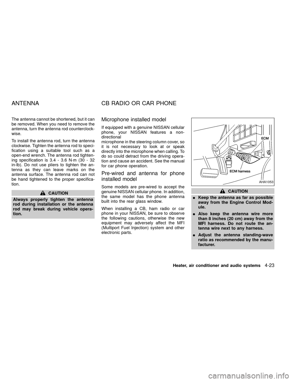
electronic parts.CAUTION
IKeep the antenna as far as possible
away from the Engine Control Mod-
ule.
IAlso keep the antenna wire more
than 8 inches (20 cm) away from the
MFI harness. Do not route the an-
tenna wire next to any harness.
IAdjust the antenna standing-wave
ratio as recommended by the manu-
facturer.
AHA1053
ANTENNA CB RADIO OR CAR PHONE
Heater, air conditioner and audio systems4-23
ZX