NISSAN FRONTIER 2021 Owners Manual
Manufacturer: NISSAN, Model Year: 2021, Model line: FRONTIER, Model: NISSAN FRONTIER 2021Pages: 492, PDF Size: 2.86 MB
Page 341 of 492
ANTI-LOCK BRAKING SYSTEM (ABS)
Page 342 of 492
Normal operation
The Anti-lock Braking System (ABS) oper-
ates at speeds above3-6mph(5-10
km/h). The speed varies according to road
conditions.
When the ABS senses that one or more
wheels are close to locking up, the actuator
rapidly applies and releases hydraulic pres-
sure. This action is similar to pumping the
brakes very quickly. You may feel a pulsa-
tion in the brake pedal and hear a noise
from under the hood or feel a vibration
from the actuator when it is operating. This
is normal and indicates that the ABS is op-
erating properly. However, the pulsation
may indicate that road conditions are haz-
ardous and extra care is required while
driving. • The ABLS system uses automatic brak-
ing to transfer power from a slipping drive
wheel to the wheel on the same axle with
more traction. The ABLS system applies
braking to the slipping wheel, which helps
redirect power to the other wheel.
• On 4–Wheel Drive models the ABLS sys- tem operates in both 4H and 4LO modes.
If 4WD mode is engaged, the ABLS sys-
tem operates for both drive axles. On
2–Wheel Drive vehicles, the ABLS system
operates on the drive axle only.
• The ABLS system is always on. In some conditions, the system may automati-
cally turn the ABLS system off. If the sys-
tem is automatically turned off, normal
brake function will continue. ABLS will
function even when the Vehicle Dynamic
Control system is turned off.
• The ABLS does not operate if both wheels on a drive axle are slipping.
Page 343 of 492
The VDC system uses various sensors to
monitor driver inputs and vehicle motion.
Under certain driving conditions, the VDC
system helps to perform the following
functions:
• Controls brake pressure to reduce wheelslip on one slipping drive wheel so power
is transferred to a non-slipping drive
wheel on the same axle.
• Controls brake pressure and engine out- put to reduce drive wheel slip based on
vehicle speed (traction control function).
• If the 4WD transfer case is shif ted into 4LO the
indicator light will come on and
the VDC system will be turned off. For
additional information, refer to “Using
4–Wheel Drive (4WD)” in this section.
• Controls brake pressure at individual wheels and engine output to help the
driver maintain control of the vehicle in
the following conditions:– Understeer (vehicle tends to not follow the steered path despite increased
steering input)
– Oversteer (vehicle tends to spin due to certain road or driving conditions)
The VDC system can help the driver to
maintain control of the vehicle, but it can-
not prevent loss of vehicle control in all driv-
ing situations. When the VDC system operates, the
indicator light in the instrument panel
flashes so note the following:
• The road may be slippery or the system
may determine some action is required
to help keep the vehicle on the steered
path.
• You may feel a pulsation in the brake pedal and hear a noise or vibration from
under the hood. This is normal and indi-
cates that the VDC system is working
properly.
• Adjust your speed and driving to the road conditions.
For additional information, refer to “Slip in-
dicator light” and ”Vehicle Dynamic Control
(VDC) OFF indicator light” in the ”Instru-
ments and controls” section of this manual.
If a malfunction occurs in the system, the
indicator light will come on in the in-
strument panel. The VDC system auto-
matically turns off when these indicator
lights are off.
The VDC OFF switch is used to turn off the
VDC system. The
indicator light illumi-
nates to indicate the VDC system is off. When the VDC OFF switch is used to turn off
the system, the VDC system still operates
to prevent one drive wheel from slipping by
transferring power to a non-slipping drive
wheel. The
indicator light flashes if this
occurs. All other VDC functions are off and
the
indicator light will not flash.
The VDC system is automatically reset to
on when the ignition switch is placed in the
OFF position then back to the ON position.
The computer has a built-in diagnostic fea-
ture that tests the system each time you
start the engine and move the vehicle for-
ward or in reverse at a slow speed. When
the self-test occurs, you may hear a clunk
noise and/or feel a pulsation in the brake
pedal. This is normal and is not an indica-
tion of a malfunction.
VEHICLE DYNAMIC CONTROL (VDC)
SYSTEM
Starting and driving5-35
Page 344 of 492
WARNING
• The VDC system is designed to help
the driver maintain stability but does
not prevent accidents due to abrupt
steering operation at high speeds or
by careless or dangerous driving
techniques. Reduce vehicle speed
and be especially careful when driv-
ing and cornering on slippery sur-
faces and always drive carefully.
• Do not modif y the vehicle's suspen-
sion. If suspension parts such as
shock absorbers, struts, springs, sta-
bilizer bars, bushings and wheels are
not NISSAN recommended for your
vehicle or are extremely deterio-
rated, the VDC system may not oper-
ate properly. This could adversely af-
fect vehicle handling performance,
and the
indicator light may flash
or theindicator light may
illuminate.
• If brake related parts such as brake
pads, rotors and calipers are not
NISSAN recommended or are ex-
tremely deteriorated, the VDC sys-
tem may not operate properly and
both the
andindicator
lights may illuminate. •
If engine control related parts are not
NISSAN recommended or are ex-
tremely deteriorated, both the
andindicator lights may
illuminate.
• When driving on extremely inclined
surfaces such as higher banked cor-
ners, the VDC system may not oper-
ate properly and the
indicator
light may flash or theindicator
light may illuminate. Do not drive on
these types of roads.
• When driving on an unstable surface
such as a turntable, ferry, elevator or
ramp, the
indicator light may
flash or theindicator light may
illuminate. This is not a malfunction.
Restart the engine af ter driving onto
a stable surface.
• If wheels or tires other than the
NISSAN recommended ones are
used, the VDC system may not oper-
ate properly and the
indicator
light may flash or theindicator
light may illuminate.
• The VDC system is not a substitute
for winter tires or tire chains on a
snow covered road.
BRAKE FORCE DISTRIBUTION
During braking while driving through turns,
the system optimizes the distribution of
force to each of the four wheels depending
on the radius of the turn.
indicator light may flash
or theindicator light may
illuminate.
5-36Starting and driving
Page 345 of 492
•If brake related parts such as brake
pads, rotors and calipers are not
NISSAN recommended or are ex-
tremely deteriorated, the VDC sys-
tem may not operate properly and
both the
and theindicator
lights may illuminate.
• If engine control related parts are not
NISSAN recommended or are ex-
tremely deteriorated, both the
andindicator lights may
illuminate.
• When driving on extremely inclined
surfaces such as higher banked cor-
ners, the VDC system may not oper-
ate properly and the
indicator
light may flash or theindicator
light may illuminate. Do not drive on
these types of roads.
• When driving on an unstable surface
such as a turntable, ferry, elevator or
ramp, the
indicator light may
flash or theindicator light may
illuminate. This is not a malfunction.
Restart the engine af ter driving onto
a stable surface. •
If wheels or tires other than the
NISSAN recommended ones are
used, the VDC system may not oper-
ate properly and the
indicator
light may flash or theindicator
light may illuminate.
• The VDC system is not a substitute
for winter tires or tire chains on a
snow covered road.
WARNING
• Never rely solely on the hill descent
control system to control vehicle
speed when driving on steep down-
hill grades. Always drive carefully and
attentively when using the hill de-
scent control system and decelerate
the vehicle speed by depressing the
brake pedal if necessary. Be espe-
cially careful when driving on frozen,
muddy or extremely steep downhill
roads. Failure to control vehicle
speed may result in a loss of control
of the vehicle and possible serious
injury or death.
• The hill descent control may not con-
trol the vehicle speed on a hill under
all load or road conditions. Always be
prepared to depress the brake pedal
to control vehicle speed. Failure to do
so may result in a collision or serious
personal injury.
The hill descent control system helps
maintain vehicle speed when driving under
15-21 mph (25-35 km/h) on steeper down-
hill grades. Hill descent control is useful
when engine braking alone in 4H or 4L can-
not control vehicle speed. Hill descent con-
trol applies the vehicle brakes to control
HILL DESCENT CONTROL SYSTEM (if
so equipped)
Starting and driving5-37
Page 346 of 492
vehicle speed allowing the driver to con-
centrate on steering while reducing the
burden of brake and accelerator operation.
• When additional braking is required onsteep downhill roads, activate the hill de-
scent control system by pushing the
switch on. For additional information, re-
fer to “Hill descent control switch” in the
“Instruments and controls” section of this
manual.
• Once the system is activated, the indica- tor light will remain on in the instrument
panel. For additional information, refer to
“Hill descent control system ON indicator
light” in the “Instruments and controls”
section of this manual.
If the accelerator or brake pedal is de-
pressed while the hill descent control sys-
tem is on, the system will stop operating
temporarily. As soon as the accelerator or
brake pedal is released, the hill descent
control system begins to function again if
the hill descent control operating condi-
tions are fulfilled.
For the best results, when descending
steep downhill grades, the hill descent con-
trol switch should be on and the shif t lever
in 2 (Second gear) or 1 (Low gear) for engine
braking.
Page 347 of 492
WARNING
• Always turn and look back before
backing up. The RSS is not a substi-
tute for proper backing procedures.
• Read and understand the limitations
of the RSS as contained in this sec-
tion. Inclement weather may affect
the function of the RSS; this may in-
clude reduced performance or a false
activation.
• This system is not designed to pre-
vent contact with small or moving
objects. •
The system is designed as an aid to
the driver in detecting large station-
ary objects to help avoid damaging
the vehicle. The system will not de-
tect small objects below the bumper,
and may not detect objects close to
the bumper or on the ground.
• If your vehicle sustains damage to
the rear bumper fascia, leaving it
misaligned or bent, the sensing zone
may be altered causing inaccurate
measurement of obstacles or false
alarms.
The RSS sounds a tone to warn the driver of
obstacles near the rear bumper when the
shif t lever is in R (Reverse). The system may
not detect objects at speeds above 3 mph
(5 km/h) and may not detect certain angu-
lar or moving objects.
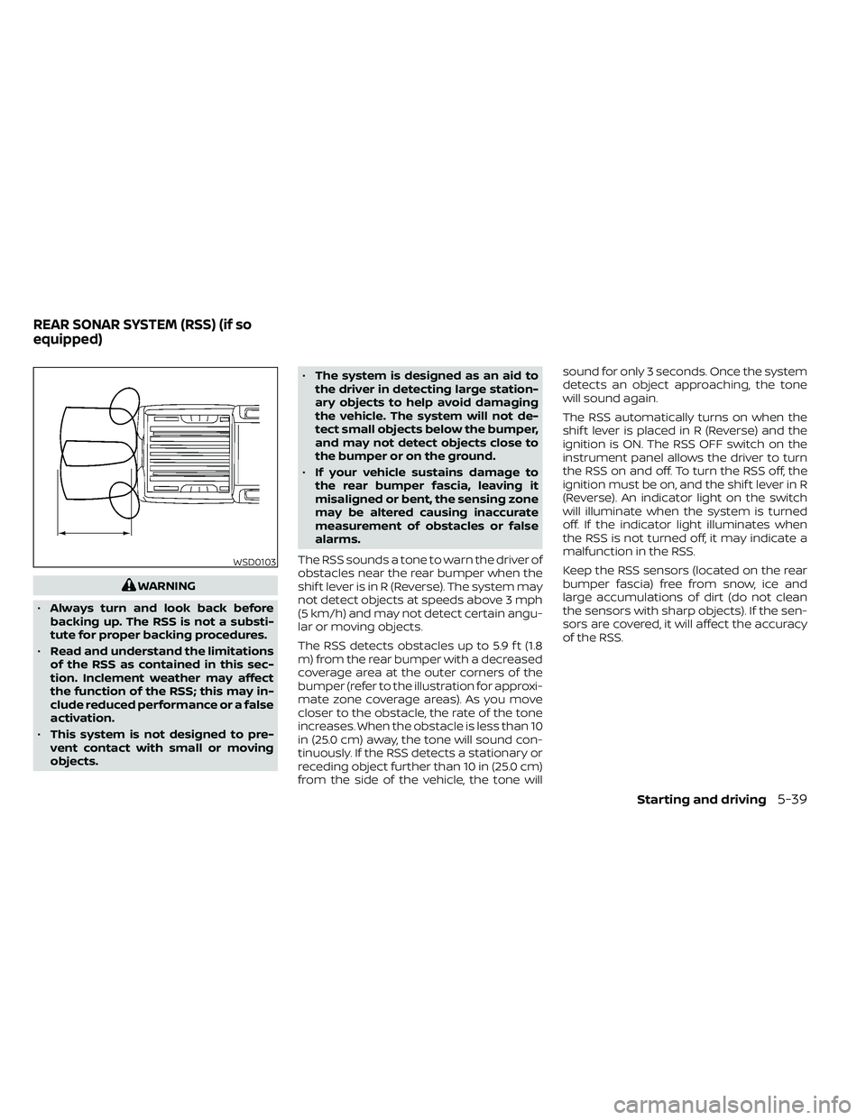
The RSS detects obstacles up to 5.9 f t (1.8
m) from the rear bumper with a decreased
coverage area at the outer corners of the
bumper (refer to the illustration for approxi-
mate zone coverage areas). As you move
closer to the obstacle, the rate of the tone
increases. When the obstacle is less than 10
in (25.0 cm) away, the tone will sound con-
tinuously. If the RSS detects a stationary or
receding object further than 10 in (25.0 cm)
from the side of the vehicle, the tone will sound for only 3 seconds. Once the system
detects an object approaching, the tone
will sound again.
The RSS automatically turns on when the
shif t lever is placed in R (Reverse) and the
ignition is ON. The RSS OFF switch on the
instrument panel allows the driver to turn
the RSS on and off. To turn the RSS off, the
ignition must be on, and the shif t lever in R
(Reverse). An indicator light on the switch
will illuminate when the system is turned
off. If the indicator light illuminates when
the RSS is not turned off, it may indicate a
malfunction in the RSS.
Keep the RSS sensors (located on the rear
bumper fascia) free from snow, ice and
large accumulations of dirt (do not clean
the sensors with sharp objects). If the sen-
sors are covered, it will affect the accuracy
of the RSS.
WSD0103
REAR SONAR SYSTEM (RSS) (if so
equipped)
Starting and driving5-39
Page 348 of 492
FREEING A FROZEN DOOR LOCK
To prevent a door lock from freezing, apply
de-icer through the key hole. If the lock
becomes frozen, heat the key before in-
serting it into the key hole or use the re-
mote keyless entry key fob (if so equipped).
ANTIFREEZE
In the winter when it is anticipated that the
temperature will drop below 32°F (0°C),
check the antifreeze to assure proper win-
ter protection. For additional information,
refer to “Engine cooling system” in the “Do-
it-yourself ” section of this manual.
BATTERY
If the battery is not fully charged during ex-
tremely cold weather conditions, the battery
fluid may freeze and damage the battery. To
maintain maximum efficiency, the battery
should be checked regularly. For additional
information, refer to “Battery” in the “Do-it-
yourself ” section of this manual.
DRAINING OF COOLANT WATER
If the vehicle is to be lef t outside without
antifreeze, drain the cooling system, includ-
ing the engine block. Refill before operating
the vehicle. For additional information, refer
to “Changing engine coolant” in the “Do-it-
yourself ” section of this manual.
TIRE EQUIPMENT
1. SUMMER tires have a tread designed toprovide superior performance on dry
pavement. However, the performance of
these tires will be substantially reduced
in snowy and icy conditions. If you oper-
ate your vehicle on snowy or icy roads,
NISSAN recommends the use of MUD &
SNOW or ALL SEASON TIRES on all four
wheels. It is recommended that you visit
a NISSAN dealer for the tire type, size,
speed rating and availability information.
2. For additional traction on icy roads, studded tires may be used. However,
some U.S. states and Canadian prov-
inces prohibit their use. Check local,
state and provincial laws before install-
ing studded tires.
Skid and traction capabilities of studded
snow tires on wet or dry surfaces may be
poorer than that of non-studded snow
tires.
3. Tire chains may be used. For additional information, refer to “Tire chains” in the
“Do-it-yourself ” section of this manual.
SPECIAL WINTER EQUIPMENT
It is recommended that the following items
be carried in the vehicle during winter:
• A scraper and stiff-bristled brush to re-move ice and snow from the windows
and wiper blades.
• A sturdy, flat board to be placed under the jack to give it firm support.
• A shovel to dig the vehicle out of snow- drif ts.
• Extra washer fluid to refill the windshield- washer fluid reservoir.
DRIVING ON SNOW OR ICE
Page 349 of 492
•Allow more stopping distance under
these conditions. Braking should be
started sooner than on dry
pavement.
• Allow greater following distances on
slippery roads.
• Watch for slippery spots (glare ice).
These may appear on an otherwise
clear road in shaded areas. If a patch
of ice is seen ahead, brake before
reaching it. Try not to brake while on
the ice, and avoid any sudden steer-
ing maneuvers.
• Do not use the cruise control on slip-
pery roads.
• Snow can trap dangerous exhaust
gases under your vehicle. Keep snow
clear of the exhaust pipe and from
around your vehicle.ENGINE BLOCK HEATER (if so
equipped)
Engine block heaters are used to assist
with cold temperature starting.
The engine block heater should be used
when the outside temperature is 20°F (-7°C)
or lower.
Page 350 of 492

MEMO
5-42Starting and driving