service NISSAN GT-R 1998 User Guide
[x] Cancel search | Manufacturer: NISSAN, Model Year: 1998, Model line: GT-R, Model: NISSAN GT-R 1998Pages: 230, PDF Size: 12.66 MB
Page 156 of 230

FULLY AUTOMATIC AIR CONDITIONER
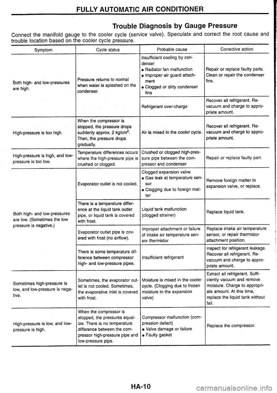
Trouble Diagnosis
by Gauge Pressure
Connect the manifold gauge to the cooler cycle (service valve). Speculate and correct the root cause and
trouble location based on the cooler cycle pressure.
Probable cause
lnsufficient cooling
by con-
denser
Radiator fan malfunction
lmproper air guard attach-
ment
Clogged or dirty condenser
fins Corrective action
Symptom Cycle status
Repair or replace faulty parts.
Clean or repair the condenser
Pressure retums to normal
when water is splashed on the
condenser. fins.
Both high- and low-pressures
are high.
Recover all refrigerant. Re-
vacuum and charge to appro-
priate amount.
Refrigerant
over-charge
When the compressor is
stopped, the pressure drops
suddenly approx.
2 kg/cm2.
Then, the pressure drops
gradually. Recover
all refrigerant. Re-
vacuum and charge to appro-
priate amount.
Air is mixed
in the cooler cycle.
High-pressure is too high.
Temperature differences occurs
where the high-pressure pipe is
crushed or clogged. Crushed
or clogged high-pres-
sure pipe between the com-
pressor and condenser
High-pressure
is high, and
low-
pressure is too low. Repair or replace
faulty part.
Evaporator outlet is not cooled. Clogged
expansion valve
Gas leak at temperature sen-
sor
Clogging due to foreign mat-
ter
There
is a temperature differ-
ence at the liquid tank outlet
pipe, or liquid tank is covered
with frost. Remove
foreign matter in
expansion valve, or replace.
Liquid tank malfunction
(clogged strainer) Replace
liquid tank.
Both high- and low-pressures
are low. (Sometimes the low
pressure is negative.)
lmproper attachment or failure
of intake air temperature sen-
sor thermistor Replace
intake air temperature
sensor, or repair
thermistor
attachment position.
Evaporator
outlet pipe is cov-
ered with frost (no airflow).
I Inspect for refrigerant leakage.
There is some temperature dif-
ference between compressor
high- and low-pressure pipes. Recover
all refrigerant.
Re-
lnsufficient refrigerant vacuum and charge to appro-
priate amount.
Extract all refrigerant. Suff
i-
ciently vacuum and remove
moisture. Charge to appropri-
ate amount. At this time,
replace the liquid tank without
fail.
Sometimes, the evaporator out-
let is not cooled. Sometimes,
the evaporative inlet is covered
with frost. Moisture
is mixed in the cooler
cycle. (Clogging due to frozen
moisture in the expansion
valve)
Sometimes
high-pressure is
low, and low-pressure is nega-
tive.
When the compressor is
stopped, the pressures equal-
ize. There is no temperature
difference between the com-
pressor high-pressure pipe and
low-pressure pipe. Compressor
malfunction
(com-
I
pression defect)
Valve damage or failure
Faulty gasket Replace
the compressor.
High-pressure
is low, and
low-
pressure
is high.
HA-I 0
Page 161 of 230

FULLY AUTOMATIC AIR CONDITIONER
Magnet Clutch System Check
MAGNET CLUTCH
Disconnect the compressor connector. Apply approx. 12V to the compressor to check the magnet clutch
operation.
/;sn
AIR CONDITIONER RELAY QJg
Remove the air conditioner relay. Apply approx. 12V between the air conditioner relay terminals No. 1 and
2. Check the relay operation sound. Ec Check the continuity between terminals No. 3 and 5.
REFRIGERANT CHARGE AMOUNT AT
Connect the manifold gauge to the vehicle side service valve.
Check that the lower pressure side (gauge pressure) is more than approx. 0.1 8 MPa (1.8 kg/cm2.G). BR
ECM
Start the engine, and short-circuit the ECM terminal No. 14 to the ground. Check the magnet clutch operation.
INTAKE AIR TEMPERATURE SENSOR
Start the engine, and short-circuit the intake air temperature sensor terminal No. 1 to the ground. Check the Rs
maanet clutch o~eration.
Blower Fan Motor System Check
BLOWER FAN MOTOR
Disconnect the blower fan motor connector. Short-circuit the blower fan motor terminals No. 2 and 5 to El!, (
the ground. Apply approx. 12V to the terminal No. 6, and check the motor operation.
Connect the blower fan motor connector. Turn the ignition switch to the ON position, and change the fan sD
switch from 1st to 4th. Check the blower fan motor terminal No. 5 with an oscilloscope. When the termi-
nal No.
5 is normal according to the following table and the fan airflow does not change, this indicates a
faulty blower fan motor.
When the terminal No.
5 results differ from the following table and the fan airflow does not change, this
indicates either a faulty harness between the blower fan motor and automatic amplifier, or a faulty auto-
matic amplifier.
Page 165 of 230

ELECTRICAL SYSTEM
SECTION EL
CONTENTS
CENTRAL DOOR LOCK SYSTEM ................................. 2
Component Parts Location .......................................... 2
Circuit Diagram ............................................................ 2
Combination Meter (meter control unit) Input/
Output Signal Specifications
........................................ 2
Inspection before Trouble Diagnoses ......................... -3
Trouble Diagnoses ....................................................... 3
REMOTE CONTROL ENTRY SYSTEM .......................... 4
Component Parts Location .......................................... 4
Circuit Diagram ............................................................ 4
Remote Control Entry Control Unit Input/Output
Signal Specifications
.................................................... 5
System Check ............................................................. -5
Inspection before Trouble Diagnoses .......................... 6
Trouble Diagnoses ....................................................... 6
Component Parts inspection ....................................... 6
ID Code Entry Procedure ............................................ 7
POWER WINDOW SYSTEM ........................................... 8
System Description ..................................................... -8
Precautions ................................................................. -8
Component Parts Location .......................................... 8
Circuit Diagram ............................................................ 9
Power Window Main Switch Input/Output Signal
Specifications
............................................................... 9
Inspection before Trouble Diagnoses ........................ 11
Trouble Diagnoses .................................................... 11
SUNROOF SYSTEM ...................................................... 12
Component Parts Location ........................................ 12
Circuit Diagram .......................................................... 12
Sunroof Switch and Sunroof Motor Assembly
lnputiOutput Signal Specifications
............................. 12
AUTO LIGHT SYSTEM ................................................. 1 3
Component Parts Location ........................................ 13
Auto Light Control Unit Input/Output Signal
Specifications
............................................................. 13
Circuit Diagram ........................................................ 14
Trouble Diagnoses .................................................. I 4
..................................... XENON HEADLAMP SYSTEM 15
Trouble Diagnoses ..................................................... 15
IGNITION KEY-OPERATED ILLUMINATION
SYSTEM
................................................................... 7
Component Parts Location ........................................ 17
.......................................................... Circuit Diagram 17
Meter Control Unit InputlOutput Signal
....................................................... Specifications 1 7
METER ........................................................................\
18
Corn bination Meter .................................................... 18
Triple Meter ................................................................ 20
................................................ COMBINATION METER 21
.................................................... System Description 21
........................................ Component Parts Location 21
Diagnosis Function .................................................... 21
................................... Meter-related Circuit Diagram 22
..................................................... Trouble Diagnoses 23
Combination Meter InpuVOutput Signal
Specifications
............................................................ -25
..................................... Component Parts Inspection 26
TRIPLE METER ............................................................. 29
Special Service Tool ................................................... 29
........................................ Component Parts Location 29
Circuit Diagram .......................................................... 29
Triple Meter InputfOutput Signal Specifications ........ 30
Component Parts Inspection ..................................... 30
IGNITION KEY WARNING BUZZER AND LIGHT
WARNING BUZZER
...................................................... 31
Component Parts Location ........................................ 31
Circuit Diagram .......................................................... 31
Meter Control Unit InpuVOutput Signal
Specifications
............................................................. 31
FRONT WIPER .............................................................. 32
Component Parts Location ........................................ 32
Circuit Diagram .......................................................... 32
Front Wiper Input/Output Signal Specifications ........ 32
Page 194 of 230

TRIPLE METER
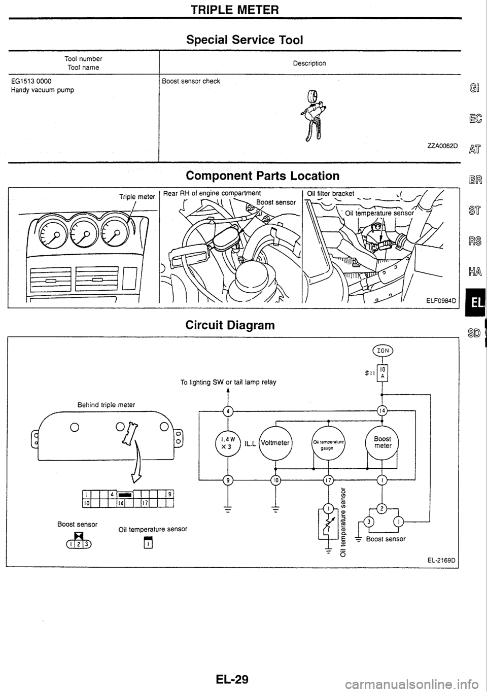
Special Service Tool
Tool number
Tool name Description
i
€GI 51 3 0000 Boost sensor
check
Handy vacuum pump
Component Parts Location
Triple meter
I
Circuit Diagram
Behind triple meter
h
To lighting SW or tail lamp relay
Boost sensor
Oil temperature sensor
* BOOS^ sensor
Page 195 of 230

TRIPLE METER
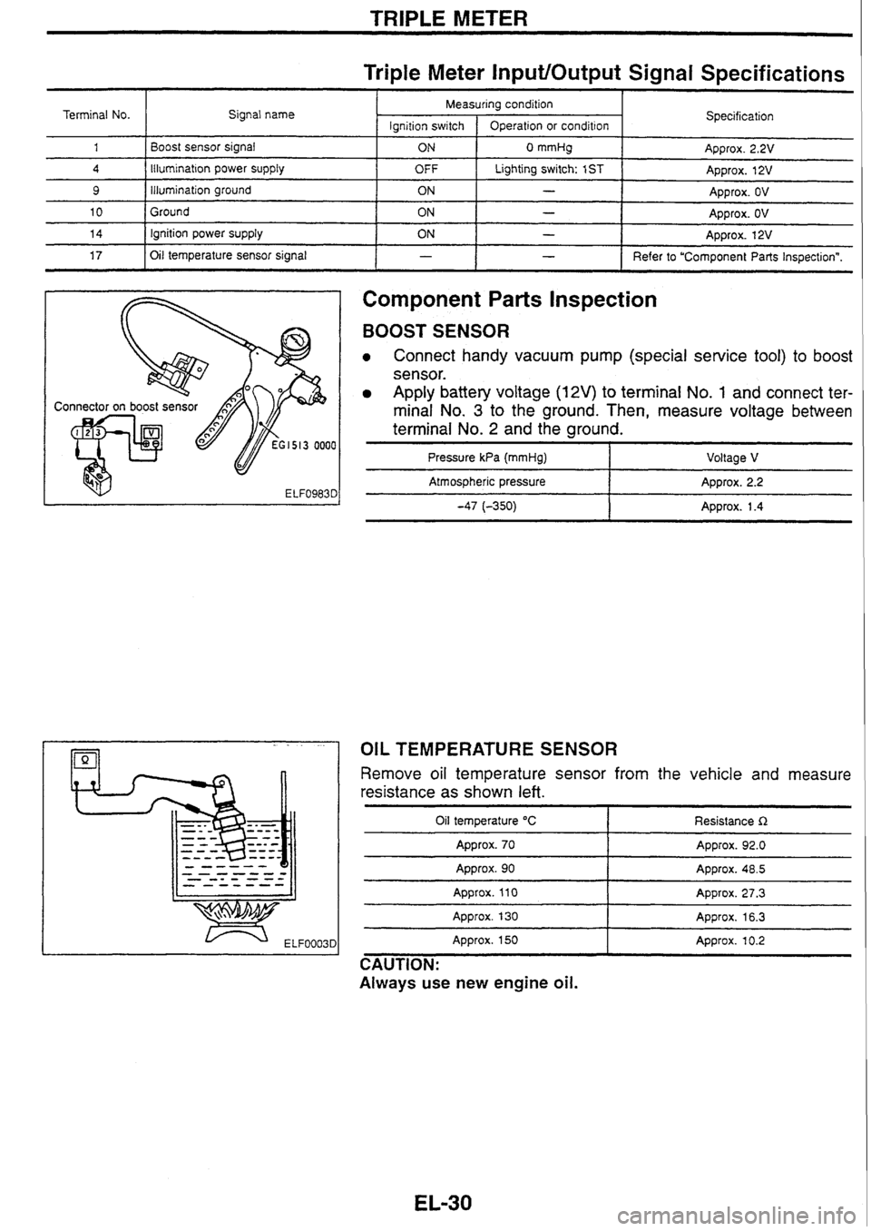
Triple Meter InputlOutput Signal Specifications
Component
Parts Inspection
Terminal No.
1
4
9
10
14
17
BOOST SENSOR
Connect handy vacuum pump (special service tool) to boost
sensor.
Apply battery voltage (12V) to terminal No. 1 and connect ter-
minal No.
3 to the ground. Then, measure voltage between
terminal No.
2 and the ground.
I I - I Refer to "Component Parts Inspectionn.
Signal
name
Boost sensor signal
Illumination
power
supply
illumination ground
Ground ignition power supply
Oil temperature sensor signal
Pressure
kPa (mmHg) I Voltage V
I
- pp Atmospheric pressure Approx. 2.2
-47 (-350) 1 Approx. 1.4
-
Specification
Approx. 2.2V
Approx. 12V
Approx. OV
Approx.
OV
Approx. 12V
Measuring condition
OIL TEMPERATURE SENSOR
lgnition
switch
ON
OFF
ON
ON
ON
Remove oil temperature sensor from the vehicle and measure
resistance as shown
left.
Operation or condition
0 mmHg
Lighting switch: 1
ST
-
-
-
Oil temperature "C
Approx. 70
-- - - --
Resistance R
Approx. 92.0
Approx. 90
Approx.
110
Approx. 130 - -- Appro~. 48.5
Approx. 27.3
Approx. 16.3
Approx. 150
Approx. 10.2
CAUTION:
Always use new engine
oil.
Page 201 of 230
![NISSAN GT-R 1998 User Guide
SERVICE DATA
SECTION SD
CONTENTS
L ] RB20DE (UB) [I 17 FS5R30A 1-
ENGINE MECHANICAL ............................................... 2 MANUAL TRANSMISSION ........................................ NISSAN GT-R 1998 User Guide
SERVICE DATA
SECTION SD
CONTENTS
L ] RB20DE (UB) [I 17 FS5R30A 1-
ENGINE MECHANICAL ............................................... 2 MANUAL TRANSMISSION ........................................](/img/5/57354/w960_57354-200.png)
SERVICE DATA
SECTION SD
CONTENTS
L ] RB20DE (UB) [I 17 FS5R30A 1-
ENGINE MECHANICAL ............................................... 2 MANUAL TRANSMISSION ........................................... 10
-1 RB25DE /I
ENGINE MECHANICAL .................................................. 4
17 RB25DET I]
ENGINE MECHANICAL .................................................. 6
CLUTCH.. . . . .. . . . . . . . . . . . . . . . . . . . . . . . . . . . . . . . . .. . .. . . . . . . . . . . . . .. . . . .+.. . . . . . . . . . -8
71 FS5W71C
MANUAL TRANSMISSION
.................... ......................... 9
AUTOMATIC TRANSMISSION ........................... .......... 12
TRANSFER .............. ......... ..... .. ... ........ . . ............. 18
PROPELLER SHAFT ................................................. 19
FRONT FINAL DRIVE ................................................. 20
REAR FINAL DRIVE ..................................................... 22
DRIVE SHAFT ............................................................... 24
AXLE & SUSPENSION ................................................. 25
ROAD WHEEL AND TIRE ............................................. 27
BRAKE. ... ...... . .. ... . .... . . . . . .... . .. .. . . .. . . .. . . . .. . . .. ... .. .. . . . . . . . . .. .... . -28
STEERING ........... ............. ..... ... ............... ...... ................ 29
SUPER HICAS ............................................................ 30