warning NISSAN GT-R 1998 Workshop Manual
[x] Cancel search | Manufacturer: NISSAN, Model Year: 1998, Model line: GT-R, Model: NISSAN GT-R 1998Pages: 230, PDF Size: 12.66 MB
Page 165 of 230

ELECTRICAL SYSTEM
SECTION EL
CONTENTS
CENTRAL DOOR LOCK SYSTEM ................................. 2
Component Parts Location .......................................... 2
Circuit Diagram ............................................................ 2
Combination Meter (meter control unit) Input/
Output Signal Specifications
........................................ 2
Inspection before Trouble Diagnoses ......................... -3
Trouble Diagnoses ....................................................... 3
REMOTE CONTROL ENTRY SYSTEM .......................... 4
Component Parts Location .......................................... 4
Circuit Diagram ............................................................ 4
Remote Control Entry Control Unit Input/Output
Signal Specifications
.................................................... 5
System Check ............................................................. -5
Inspection before Trouble Diagnoses .......................... 6
Trouble Diagnoses ....................................................... 6
Component Parts inspection ....................................... 6
ID Code Entry Procedure ............................................ 7
POWER WINDOW SYSTEM ........................................... 8
System Description ..................................................... -8
Precautions ................................................................. -8
Component Parts Location .......................................... 8
Circuit Diagram ............................................................ 9
Power Window Main Switch Input/Output Signal
Specifications
............................................................... 9
Inspection before Trouble Diagnoses ........................ 11
Trouble Diagnoses .................................................... 11
SUNROOF SYSTEM ...................................................... 12
Component Parts Location ........................................ 12
Circuit Diagram .......................................................... 12
Sunroof Switch and Sunroof Motor Assembly
lnputiOutput Signal Specifications
............................. 12
AUTO LIGHT SYSTEM ................................................. 1 3
Component Parts Location ........................................ 13
Auto Light Control Unit Input/Output Signal
Specifications
............................................................. 13
Circuit Diagram ........................................................ 14
Trouble Diagnoses .................................................. I 4
..................................... XENON HEADLAMP SYSTEM 15
Trouble Diagnoses ..................................................... 15
IGNITION KEY-OPERATED ILLUMINATION
SYSTEM
................................................................... 7
Component Parts Location ........................................ 17
.......................................................... Circuit Diagram 17
Meter Control Unit InputlOutput Signal
....................................................... Specifications 1 7
METER ........................................................................\
18
Corn bination Meter .................................................... 18
Triple Meter ................................................................ 20
................................................ COMBINATION METER 21
.................................................... System Description 21
........................................ Component Parts Location 21
Diagnosis Function .................................................... 21
................................... Meter-related Circuit Diagram 22
..................................................... Trouble Diagnoses 23
Combination Meter InpuVOutput Signal
Specifications
............................................................ -25
..................................... Component Parts Inspection 26
TRIPLE METER ............................................................. 29
Special Service Tool ................................................... 29
........................................ Component Parts Location 29
Circuit Diagram .......................................................... 29
Triple Meter InputfOutput Signal Specifications ........ 30
Component Parts Inspection ..................................... 30
IGNITION KEY WARNING BUZZER AND LIGHT
WARNING BUZZER
...................................................... 31
Component Parts Location ........................................ 31
Circuit Diagram .......................................................... 31
Meter Control Unit InpuVOutput Signal
Specifications
............................................................. 31
FRONT WIPER .............................................................. 32
Component Parts Location ........................................ 32
Circuit Diagram .......................................................... 32
Front Wiper Input/Output Signal Specifications ........ 32
Page 186 of 230

COMBINATION METER
System Description
Speedometer, tachometer, odoltrip meter, fuel gauge, and
water temperature gauge are integrally controlled by the con-
trol circuit in the meter control unit.
Diagnosis function has odoltrip meter segment check, low fuel @
warning lamp check, and continuity check in the meter control
circuit and the meters (speedometer, tachometer, fuel gauge,
and water temperature gauge).
Component Parts Location
Combination meter ABS unit
ID Transfer (4WD) I H side of trunk room
I -unit connector I
/I Diagnosis Function
meter is displayed, turn the ignition switch ACC or
down the odoltrip meter switch, turn the ignition switch
/
ON.
3. Verify that 0000.0 km is displayed on the trip meter.
4. Press the odoltrip meter switch 3 times within 5 seconds.
5. All the odoltrip meter segments light up along with low fuel
warning lamp.
EL-21
SEGMENT CHECK AND LOW FUEL WARNING LAMP
CHECK
Page 187 of 230

COMBINATION METER
Diagnosis Function
(Cont'd)
METER CIRCUIT CHECK
After the segment check, press the odohrip meter switch to
verify that meters operate as shown below. (Low fuel warning
lamp goes off at this point.)
i
ELF0967D I It takes 1 minute for the meters to become stable.
DIAGNOSIS FUNCTION CANCELLATION
Turn the ignition switch ACC or OFF.
Meter-related Circuit Diagram
I I TO oil pressure W.L
Page 188 of 230

COMBINATION METER
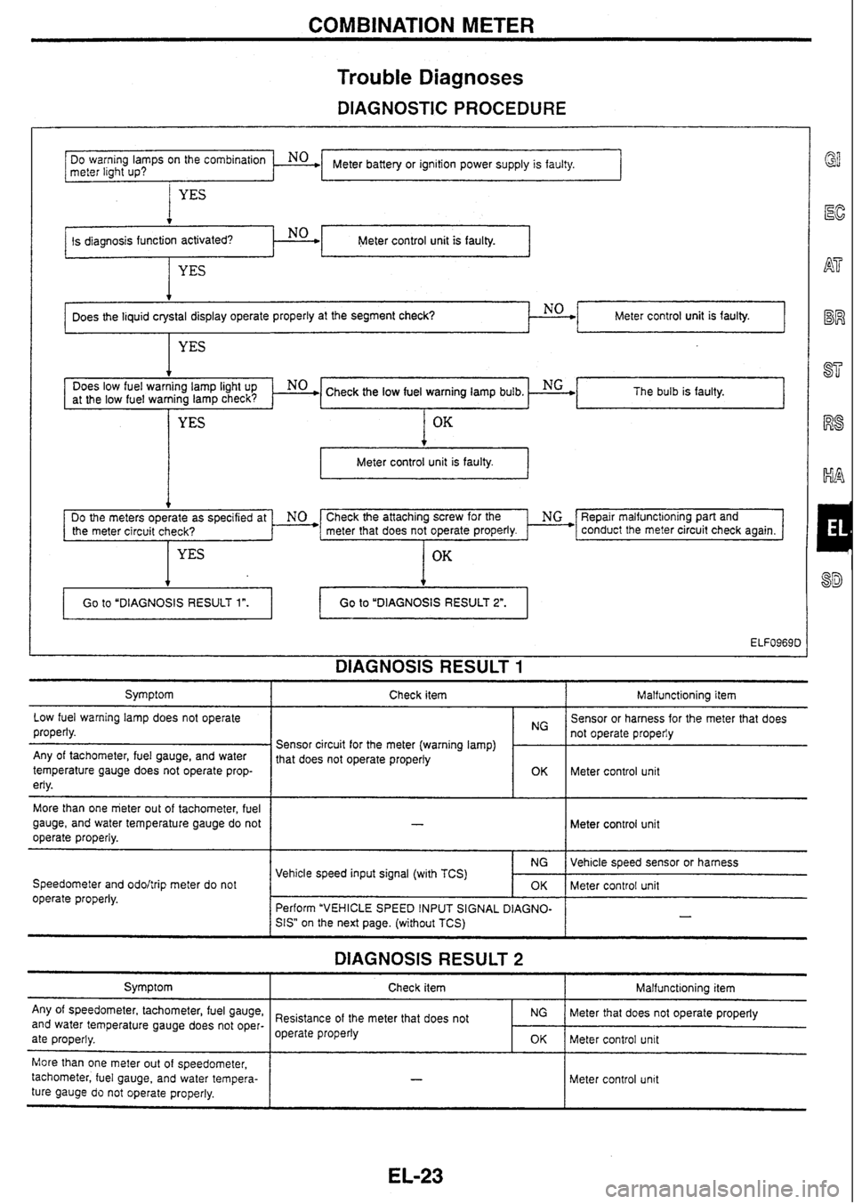
Trouble
Diagnoses
DIAGNOSTIC PROCEDURE
I YES
Meter control unit is faulty.
Meter battery or ignition power supply is faulty.
DO
warning
lamps
on
the
meter light
up?
. No .
at the low fuel warning lamp check? The bulb
is faulty.
t
Meter control unit is faulty. I
Does the liquid crystal display operate properly at the segment check? NO
Check the attaching screw for the ' NG *F3epair malfunct~oning part and
the meter circuit check? meter that
does not operate properly. * conduct the meter circuit check again.
OK
Meter control unit is faulty.
YES
DIAGNOSIS RESULT 1
4
Symptom I Check item I Malfunctioning item
Go
to "DIAGNOSIS RESULT
1".
Low fuel warning lamp does not operate
properly. Go to
"DIAGNOSIS RESULT
2".
Any of tachometer, fuel gauge, and water
temperature gauge does not operate prop-
erly.
More than one meter out of tachometer, fuel
gauge, and water temperature gauge do not
operate properly.
Speedometer and
odohrip meter do not
operate properly. Sensor
or harness for the meter that does
Sensor circuit for the meter (warning lamp)
1 1: 1 not operate properiy
1 that does not operate properly
~ Meter control unit
Meter control unit
DIAGNOSIS RESULT 2
Symptom
Any of speedometer, tachometer, fuel gauge,
and water temperature gauge does not oper-
ate properly. Vehicle
speed sensor or harness
Meter control unit
-
Vehicle speed input signal (with TCS)
Check item
I Malfunctioning item
NG
OK
Perform "VEHICLE SPEED INPUT SIGNAL
DIAGNO-
SIS"
on the next page. (without TCS)
More than one meter out of speedometer,
tachometer, fuel gauge, and water tempera-
ture gauge
do not operate properly. Resistance
of the meter that does not
operate properly
Meter control unit
NG
OK
- -
Meter that does not operate properly
Meter control unit
Page 189 of 230

COMBINATION METER
Trouble Diagnoses (Cont'd)
VEHICLE SPEED INPUT SIGNAL DIAGNOSIS
I Connector
WARNING LAMP CHECK Does ABS warning lamp remain ON with
ignition switch ON?
ABS I
Perform ABS self-diagnosis
and check faulty circuit.
Refer to
BR section ("ABS
SYSTEMn).
Continuity exists.
Terminal No. 19 and ground:
No continuity
. -- I I
HARNESS CHECK ' Disconnect ABS control unit connector
(TK24)
and meter connector (TK20
Brown).
Terminals No. 19 - 24:
OK
El f
Meter control unit connector on vehicle
NG+'
I - = 'ELF0970D
El
@EM
Meter control unit connector on vehicle rn
rm-1 ffee
1
L / - - -
ELFo971D -
ABS control unit to meter
harness is faulty.
Meter control unit
is faulty. VEHICLE SPEED INPUT SIGNAL
CHECK 1 Connect meter connector (TK20 Brown). Terminal No. 19 and around:
'2
" Approx. 9V
OK
r9 v
VEHICLE SPEED INPUT SIGNAL
CHECK 2 Connect ABS control unit connector
(TK24).
Start the engine and drive the vehicle. Terminal No. 19 and ground:
Specification
Refer to "Combination Meter InpuffOutput
Signal Specificationsn on the next page.
OK
Meter control unit is faulty.
5' Pelform ABS self-diagnosis and check faulty circuit.
Refer to BR section ("ABS
SYSTEMn).
Page 193 of 230

COMBINATION METER
Component Parts Inspection (Cont'd)
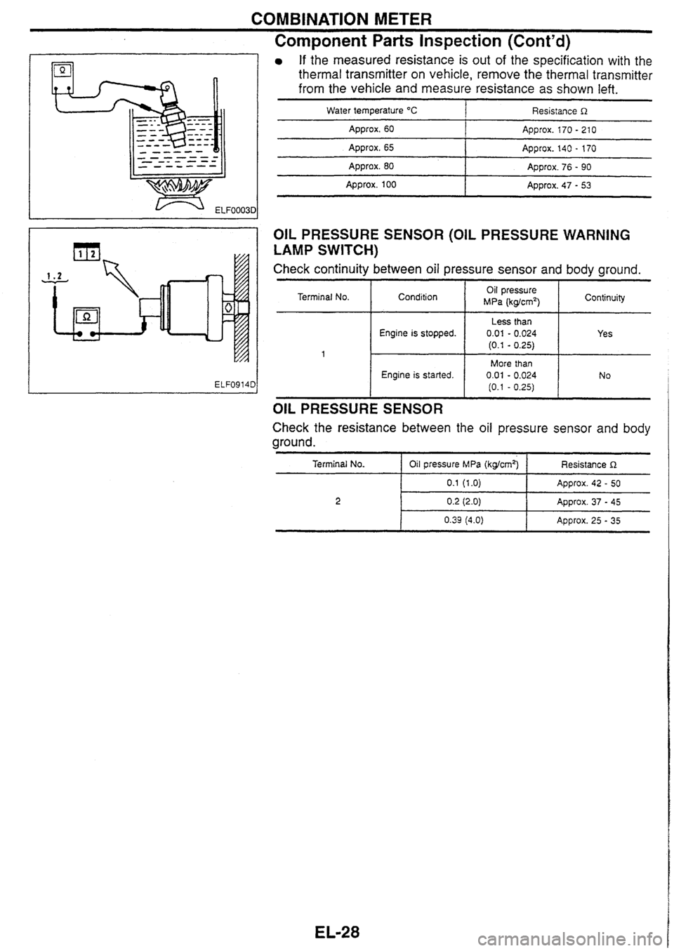
If the measured resistance is out of the specification with the
thermal transmitter on vehicle, remove the thermal transmitter
from the vehicle and measure resistance as
shown left.
Water temperature "C 1 Resistance R
Approx. 60 I Approx. i70 - 21 0
Approx. 65 I Approx. 140 - 170
Approx. 80 I Approx. 76 - 90
I
- - -- Appro~. 100 Approx. 47 - 53
OIL PRESSURE SENSOR (OIL PRESSURE WARNING
LAMP SWITCH)
Check continuity between oil pressure sensor and body ground.
Terminal No.
OIL PRESSURE SENSOR
Engine is stopped.
Engine is started.
Check the resistance between the oil pressure sensor and body
ground.
Condition
Terminal No.
I Oil pressure MPa (kgkmq-1 Resistance R
Oil pressure
MPa (kg/cm2) 1 Continuity
Less than
0.01 - 0.024
(0.1 - 0.25)
More than 0.01 - 0.024
(0.1 - 0.25)
0.2 (2.0) Approx. 37 - 45
Yes
No
Page 196 of 230

IGNITION KEY WARNING BUZZER AND LIGHT WARNING BUZZER
I Behind combination meter
Meter control unit Component Parts Location
J
Circuit Diagram
Meter Control Unit
InputlOutput Signal
Specifications
Terminal No.
Driver door switch signal
Signal
name
OFF Measuring condition
Ignition switch
I Measuring method Specification
Driver door switch
29
ON (Open)
OFF (Closed)
42
Approx. OV
Approx. 12V
Ignition power supply
54
55
Key-in detection switch
signal 1 OFF
ON
Lighting switch signal
Ground Approx. 12V
Remove
the ignition key.
Insert the ignition key. Approx. OV
Approx. 12V
Approx. 12V
Approx. OV
Approx. OV
I
OFF
ON Lighting
switch: 1 ST ON
OFF
-
Page 228 of 230

BRAKE
BRAKING FORCE
More than 10% of axle
weight
REAR DlSC BRAKE
Total braking force of rear wheels
Variation between right and left of
each wheel Brake
type
Less than 8% of axle weight ADllVC
9.3
Brake
pad
Disc rotor
Total
braking force OPZ11V
11.5
Standard
thickness (New) mm
Wear limit of thickness mm
Standard thickness (New) mm
Wear limit of thickness mm
Runout limit mm
More than 50%
of vehicle
weight at inspected
Note: The braking force when both front wheels are locked up can be considered to meet the total braking force.
2.0
16
14
BRAKE PEDAL
18
16
PARKING BRAKE
Free play (at pedal top surface)
mm I 3 - 11 Less than
0.07 Type DS17HD I
Brake
lining
Depressed pedal height under force
of 490 N (50 kg)
(from dash panel top surface)
mm
Brake
pedal height
(from dash panel top surface)
mm
Standard inner diameter
I (New) mm I
Standard thickness (New) mrn
Wear limit of thickness
mm M/T: 163 - 173 IVT: 170 - 180
172 dia. 3.0 1.5
M/T: More
than 85 A. More than 90 . . Drum I
I
Wear limit of inner diameter
mm I 173 dia.
Clearance between the edge of stop
lamp switch screw and pedal stopper
mm Operating
stroke
[under force of 196 N (20
kg)] 5 - 7 notches
CHECK VALVE I
I
Maximum stroke
19 notches
Number of notches when brake warning
lamp turns on
TIGHTENING TORQUE
Unit: N.m (kg-m)
Within 1 notch
Vacuum leakage
[at
vacuum Of 66'7 kPa (-500 mmHg)]
BRAKE BOOSTER
Within 1.3 kPa (10 mmHg) of
vacuum for 15 seconds
Master cylinder fixing nut
I 12 - 14 (1.2 - 1.5)
Vacuum leakage
[at vacuum of 66.7
kPa
(-500
mmHg)l
Within 3.3
kPa
(25
mmHg)
of
vacuum for 15 seconds Front
caliper mounting bolt
Brake tube flare nut -- - 152 - 154 (15.5 - 15.8)
15
- 17 (1.5 - 1.8)
FRONT DlSC BRAKE
Input rod standard length at installed
mm
Brake type
I AD25VB I CUSVD [OPZ~~VC
140
Standard thickness
Wear limit of
thickness
Standard thickness
mm
1 22 1 26 1 30
Disc rotor Wear limit of
thickness
Runout
limit Less than 0.07