4WD NISSAN GT-R 1998 Service Manual
[x] Cancel search | Manufacturer: NISSAN, Model Year: 1998, Model line: GT-R, Model: NISSAN GT-R 1998Pages: 230, PDF Size: 12.66 MB
Page 18 of 230

ENGINE AND EMISSION CONTROL OVERALL SYSTEM
Circuit Diagram
RB20DE (UB).MTT, RB25DE, RB25DET.MTT MODELS
Fan motor
Auxtliary
electric
Ian
relay
-
Alr cmdll~oner compressor
Arr
conduoner
relay
14
Y Mallunct~on indcator lamp A 17
26 $7 = Power steenng 011
pressure sw~icr.
I
23
43 Engine Want
temwrature sensor B.
Tachometer drive signal Check connmr
To rear defogger relay
/ [RB2MWD TO starter motor *'""L'*" - > TO PNP switch
I TO Starter relay
[Except lor ' - RB25DE.4WDI
Page 20 of 230

ENGINE AND EMISSION CONTROL OVERALL SYSTEM
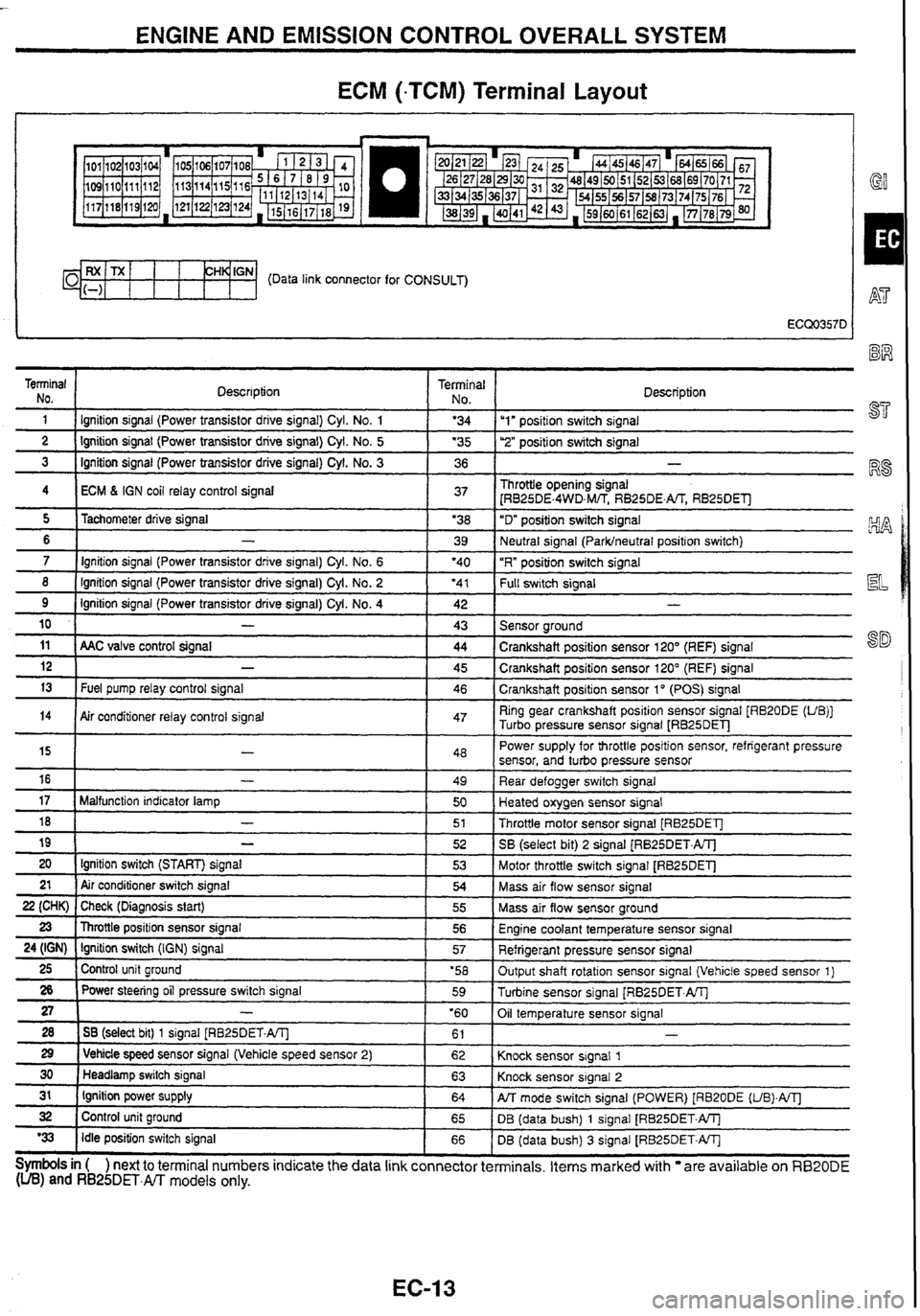
ECM (-TCM) Terminal Layout
I GY
CH~'GN- (Data link connector for CONSULT)
Terminal NO.
1 Description Terminal 1 No I Description - - 1 I lgnition
signal (Power transistor drrve signal) Cyl. No. 1 1 '34 Iu1" positron switch signal -- ---- 2 1 Ignition signal (Power transistor drive signal) Cyl. No. 5 1 '35 1 ''2" posifion switch signal - - 3 1 Ignition signal (Power transistor drive signal) Cyl. No. 3 1 36 1 -
4 I ECM 6 IGN coil relay control signal 1 37 1 Throttle opening signal
[RB25DE.4WD,M/TS RB25DE.m RB25DEll
- - - -- - - - - 8 ( Ignition signal (Power transistor drive signal) Cyl. No. 2 ( '41 1 f-k swltch signal
5
6
7
11 ( AAC valve control signal ( 44 1 Crankshaft position sensor 120' (REF) signal
Tachometer
drive signal
-
Ignition signal (Power transistor drive signal) Cyl. No. 6
9
10
'38
39
'40
Ignition signal (Power transistor drive signal)
Cyl.
No. 4
-
12
13
"D" position switch signal
Neutral signal
(Parklneutral position switch)
"R" position switch signal
14
Symbols in ( ) next to terminal numbers indicate the data link connector terminals. Items marked with are available on RB20DE (UB) and RB25DET.m models only.
42
43
-
Fuel pump relay control signal
15
16
17
18
19
20 21
22 (CHK)
23
24 (IGN)
25
26
27
28
29
30
31
32
'33
- -
Sensor around
Air conditioner relay control signal 45
46
-
-
Malfunction indicator lamp
-
-
Ignition switch (START) signal
Air conditioner switch signal
Check (Diagnosis start)
Throttle position sensor signal
Ignition switch
(IGN) signal
Control unit ground
Power steering oil pressure switch signal
-
1 SB (select bit) 1 signal [RB25DET.A/Tl
1 Vehicle speed sensor signal (Vehicle speed sensor 2)
Headlamp switch signal
Ignition power supply
Control unit ground
Idle position switch signal Crankshaft
position sensor 120" (REF) signal
Crankshaft position sensor 1
" (POS) signal
47 Ring gear crankshaft position sensor signal [RB20DE (UB)]
Turbo pressure sensor signal
LRB25DEl-J
48
49
50
51
52
53
54
55
56
57
'58 59
'60 61
62
63
64
65
66 Power
supply for throttle position sensor, refrigerant pressure
sensor, and turbo pressure sensor
Rear defogger switch signal
Heated oxygen sensor signal
Throttle motor sensor signal [RB25DET]
SB
(select bit)
2 signal (RB25DET.ATJ
Motor throttle switch signal
[RB25DET]
Mass air flow sensor signal
Mass air flow sensor ground
Engine coolant temperature sensor signal
Refrigerant pressure sensor signal
Output shaft rotation sensor signal (Vehicle speed sensor 1)
Turbine sensor signal
[RB25DET.AlTj
Oil temperature sensor signal
Knock sensor signal
1
Knock sensor signal 2
PJT mode switch signal (POWER) [RB20DE (UB).A/Tl
DB (data bush) 1 signal [RB25DET.W
DB (data bush)
3 signal [RB25DET.W
Page 43 of 230

TROUBLE DlAGNOSES
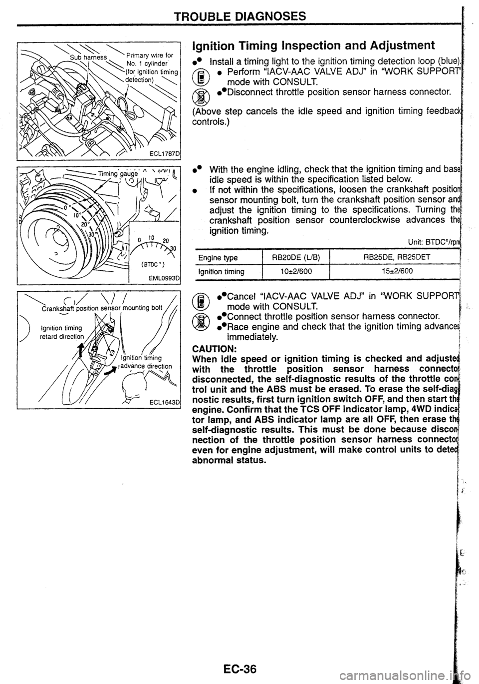
Ignition Timing inspection and Adjustment
lnstall a timing light to the ignition timing detection loop (blue)
A3 e Perform "IACV-AAC VALVE ADJ" in "WORK SUPPORT
mode with CONSULT.
/Ci3 Disconnect throttle position sensor harness connector.
w (Above step cancels the idle speed and ignition timing feedbacl
cont rots.)
Cancel "IACV-AAC VALVE ADJ" in "WORK SUPPORl
@ mode with CONSULT.
Connect throttle position sensor harness connector.
Race engine and check that the ignition timing advana
immediately.
With the engine idling, check that the ignition timing and bas1
idle speed is within the specification listed below.
If not within the specifications, loosen the crankshaft positio
sensor mounting bolt, turn the crankshaft position sensor
an
adjust the ignition timing to the specifications. Turning th
crankshaft position sensor counterclockwise advances th
ignition timing.
Unit: BTDCO/rpl
CAUTION:
When idle speed or ignition timing is checked and adjuste
with the throttle position sensor harness
connectc
disconnected, the self-diagnostic results of the throttle
COI
trol unit and the ABS must be erased. To erase the self-dia!
nostic
results, first turn ignition switch OFF, and then start tt
engine. Confirm that the
TCS OFF indicator lamp, 4WD indic
tor lamp, and
ABS indicator lamp are all OFF, then erase tt
self-diagnostic results. This must be done because disco
nection
of the throttle position sensor harness connectc
even for engine adjustment,
will make control units to dete
abnormal status.
RB25DE, RB25DET
15*2/600 Engine type
Ignition timing
RB20DE (VB)
1 O-e2/600
Page 48 of 230

TROUBLE DIAGNOSES
ECM (*TCM) InpuWOutput Signal Reference
Value (Cont'd)
Terminal
No.
41
NOTE: I
Signal name At
idle
rlehicle speed sen-
;or signal
dead lamp switch Light switch OFF: Approx. OV
;ignal
Light switch ON: Battery voltage
gnition power
sup- Ignition switch OFF: Approx. OV
)iY Ignition switch ON: Battery voltage
dle position switch
lB25DET.m
Mottle
opening Accelerator pedal released: Approx.
0.5V
ignal
Accelerator pedal fully depressed: Approx.
4.2V RB25DE.4WD.W
(Ignition switch ON, engine not running) ; RB25D€.AlT,
3R25Dm
Jeutral signal Selector lever in Neutral or in
N or P position: Approx. OV ParWNeutral posi- Selector lever in other positions: Approx. 4.8V
on switch)
:ull switch signal Accelerator pedal released: Approx. OV
?B20DE
(UB), Accelerator pedal fully depressed: Battery voltage
lB25DET-A/Tl (Ignition switch ON, engine not running)
- - - - -- - love voltages are measured values obtained by analog
At approx. 2,000 rpm
IRB20DE
(UB)] When driving at approx. 40 km/h: Approx. 2.4V @I
i ECL 1 7920
[RB25DE, RB25DETI
When driving at approx. 40
kmk: Approx. 2.4V %R
Approx. OV
(When accelerator pedal is depressed)
Approx.
0.N
rcuit tester.
Page 186 of 230

COMBINATION METER
System Description
Speedometer, tachometer, odoltrip meter, fuel gauge, and
water temperature gauge are integrally controlled by the con-
trol circuit in the meter control unit.
Diagnosis function has odoltrip meter segment check, low fuel @
warning lamp check, and continuity check in the meter control
circuit and the meters (speedometer, tachometer, fuel gauge,
and water temperature gauge).
Component Parts Location
Combination meter ABS unit
ID Transfer (4WD) I H side of trunk room
I -unit connector I
/I Diagnosis Function
meter is displayed, turn the ignition switch ACC or
down the odoltrip meter switch, turn the ignition switch
/
ON.
3. Verify that 0000.0 km is displayed on the trip meter.
4. Press the odoltrip meter switch 3 times within 5 seconds.
5. All the odoltrip meter segments light up along with low fuel
warning lamp.
EL-21
SEGMENT CHECK AND LOW FUEL WARNING LAMP
CHECK