relay NISSAN GT-R 1998 Service Manual
[x] Cancel search | Manufacturer: NISSAN, Model Year: 1998, Model line: GT-R, Model: NISSAN GT-R 1998Pages: 230, PDF Size: 12.66 MB
Page 9 of 230
ENGINE AND EMISSION CONTROL OVERALL SYSTEM
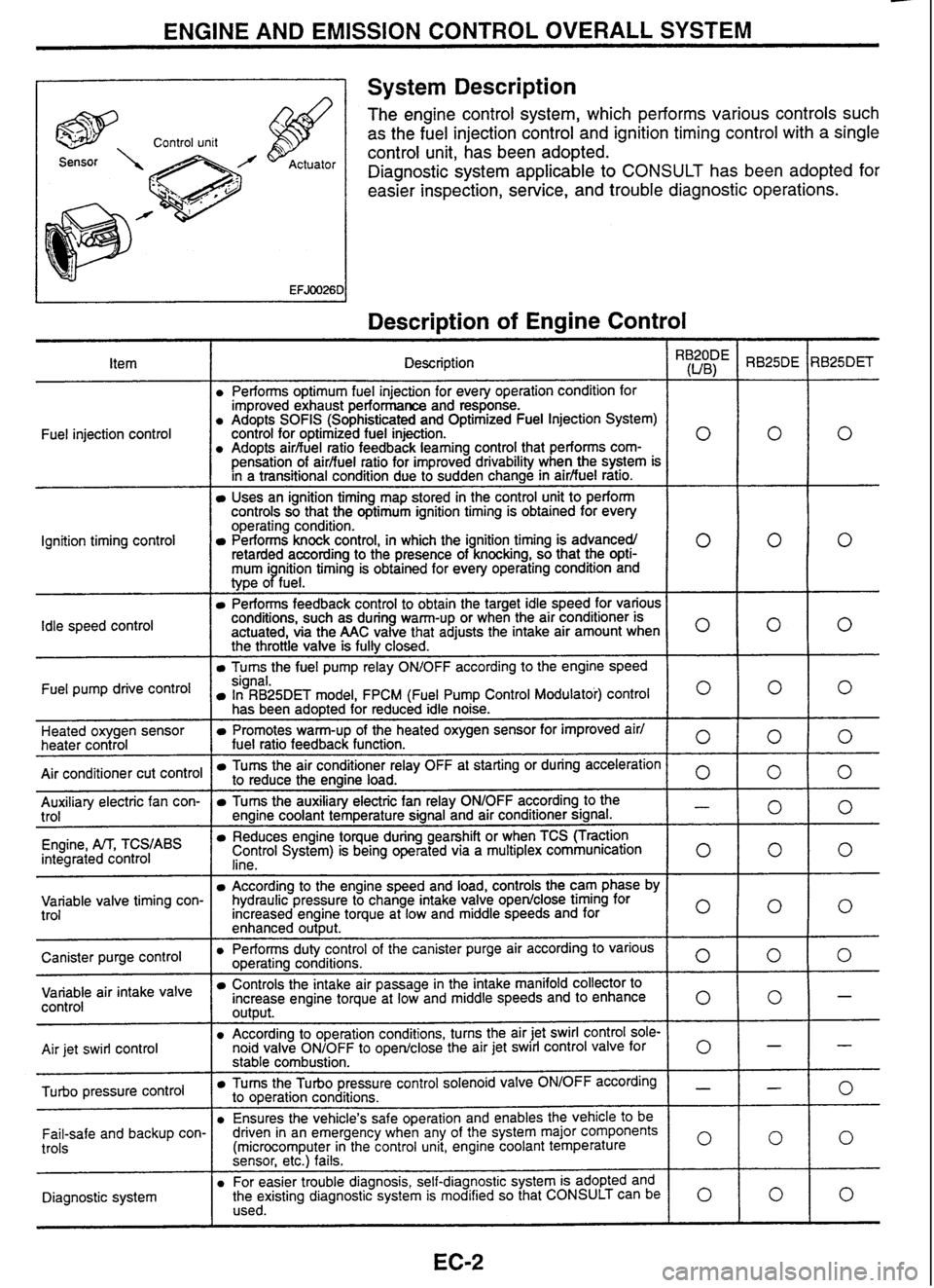
A 1 System Description
The engine control system, which performs various controls such
as the fuel injection control and ignition timing control with a single
control unit, has been adopted.
Diagnostic system applicable to
CONSULT has been adopted for
easier inspection, service, and trouble diagnostic operations.
Description of Engine Control
I
Description \,
Performs optimum fuel injection for every operation condition for
improved exhaust performance and response.
Adopts
SOFlS (Sophisticated and Optimized Fuel Injection System)
control for optimized fuel injection.
Adopts
airbuel ratio feedback
learning control that performs
com-
0
pensation of airfiuel ratio for improved drivability when the system is
in a transitional condiiion due to sudden change in
airfiuel ratro.
Uses an ignition timing map stored in the control unit to perform
controls so that the optimum ignition timing is obtained for every
operating condition.
Performs knock control, in which the ignition timing is advancedl
retarded according to the presence of knocking, so that the
opti- 0
mum i nition timing is obtained for every operating condition and
type
oPfue1.
Performs feedback control to obtain the target idle speed for various
conditions, such as during warm-up or when the air conditioner is
actuated, via the
AAC valve that adjusts the intake air amount when
O
the throttle valve is fully closed.
Turns the fuel pump relay OWOFF according to the engine speed
Fuel
injection control
Ignition timing control
Idle
speed
control
Fuel pump drive signal. In RB25DET model, FPCM (Fuel Pump Control Modulatoi) control O
has been adopted for reduced idle noise.
Heated oxygen sensor
heater control
Air conditioner cut control
Promotes warm-up of the heated oxygen sensor for improved air1
fuel ratio feedback function. 0
Tums the air conditioner relay OFF at starting or during acceleration to reduce the engine load. 0 -- Auxiliary electric fan con-
trol
Engine,
M, TCS,ABS integrated control
Tums the auxiliary electric fan relay ONIOFF according to the - engine coolant temperature signal and air conditioner signal.
Reduces engine toque during gearshift or when TCS (Traction
Control System) is being operated via a multiplex communication
lino 0
- -
Variable valve timing con-
trol According to the engine speed and load, controls the cam phase by
hydraulic pressure to change intake valve
open/close timing for
Increased engine torque at low and middle speeds and for
enhanced
out~ut.
I o I
Canister purge control air
intake valve control
Air
jet swirl control Performs duty
control of the canister purge air according to various ooeratina conditions.
0 -r-~ e-- ---
-
Controls the intake air passage in the intake manifold collector to
increase engine torque at low and middle speeds and to enhance
output. 0
According to operation conditions, turns the air jet swirl control sole-
noid valve ONIOFF to openlclose the air jet swirl control valve
for 0
pressure control
stable combustion.
Tums the Turbo pressure control solenoid valve ONIOFF according - to operation conditions.
Ensures the vehicle's safe operation and enables the vehicle
to be
Fail-safe and backup con-
trols
Diagnostic system driven
in an emergency when any of the system major components
(microcomputer in the control unit, engine coolant temperature
0
sensor, etc.) fails.
For easier trouble diagnosis, self-diagnostic system is adopted and
the existing diagnostic system is modified so that CONSULT can be
0 used.
Page 13 of 230
ENGINE AND EMISSION CONTROL OVERALL SYSTEM
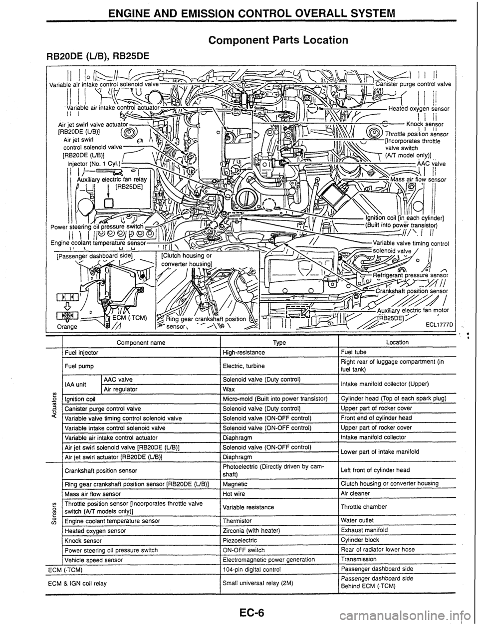
Component Parts Location
RB20DE (UB), RB25DE
Component name I Type I Location
I Fuel iniector I Hiah-resistance I Fuel tube
I Fuel pump I Electric, turbine I Right rear of luggage compartment (in
fuel tank)
AAC valve
IAA
unit Air reaulator
5 m 3 '
Solenoid valve (Duty control)
Wax
variable intake control solenoid valve
Variable air intake control actuator
Air jet swirl solenoid valve
[RBPODE (UB)]
Air jet swirl actuator
[RB20DE (LIB)]
Crankshaft position sensor Ring gear crankshaft position sensor
[RB20DE (UB)]
Mass air flow sensor Intake
manifold collector (Upper)
Ignition coil
Canister purge control valve
Variable valve tirnina control
solenoid valve
(? o C
Solenoid valve (ON-OFF control)
Diaphragm
Solenoid valve (ON-OFF control)
Diaphragm Photoelectric (Directly driven by cam-
shaft)
Magnetic
Hot wire
w v,
Micro-mold (Built into power transistor)
Solenoid valve (Duty control)
Solenoid valve (ON-OFF control) Upper part of rocker cover
Intake manifold collector
Lower part of intake manifold
Left front
of cylinder head
Clutch housing or converter housing
Air cleaner
Throttle position sensor [Incorporates throttle valve
switch
(All models only)]
Power steering oil pressure switch
Vehicle speed sensor
ECM
(.TCM)
ECM
& IGN coil relay Cylinder head
(Top of each spark plug)
Upper part of rocker cover
Front end of cylinder head
Engine coolant temperature sensor
Heated oxygen sensor
Knock sensor Variable
resistance
ON-OFF switch
Electromagnetic power generation
104-pin digital control
Small universal relay (2M) Throttle chamber
Thermistor
Zirconia (with heater)
Piezoelectric Rear of radiator lower hose
Transmission Passenger dashboard side
Passenger dashboard side
Behind ECM
(.TCM) Water
outlet
Exhaust manifold
Cylinder block
Page 14 of 230
ENGINE AND EMISSION CONTROL OVERALL SYSTEM
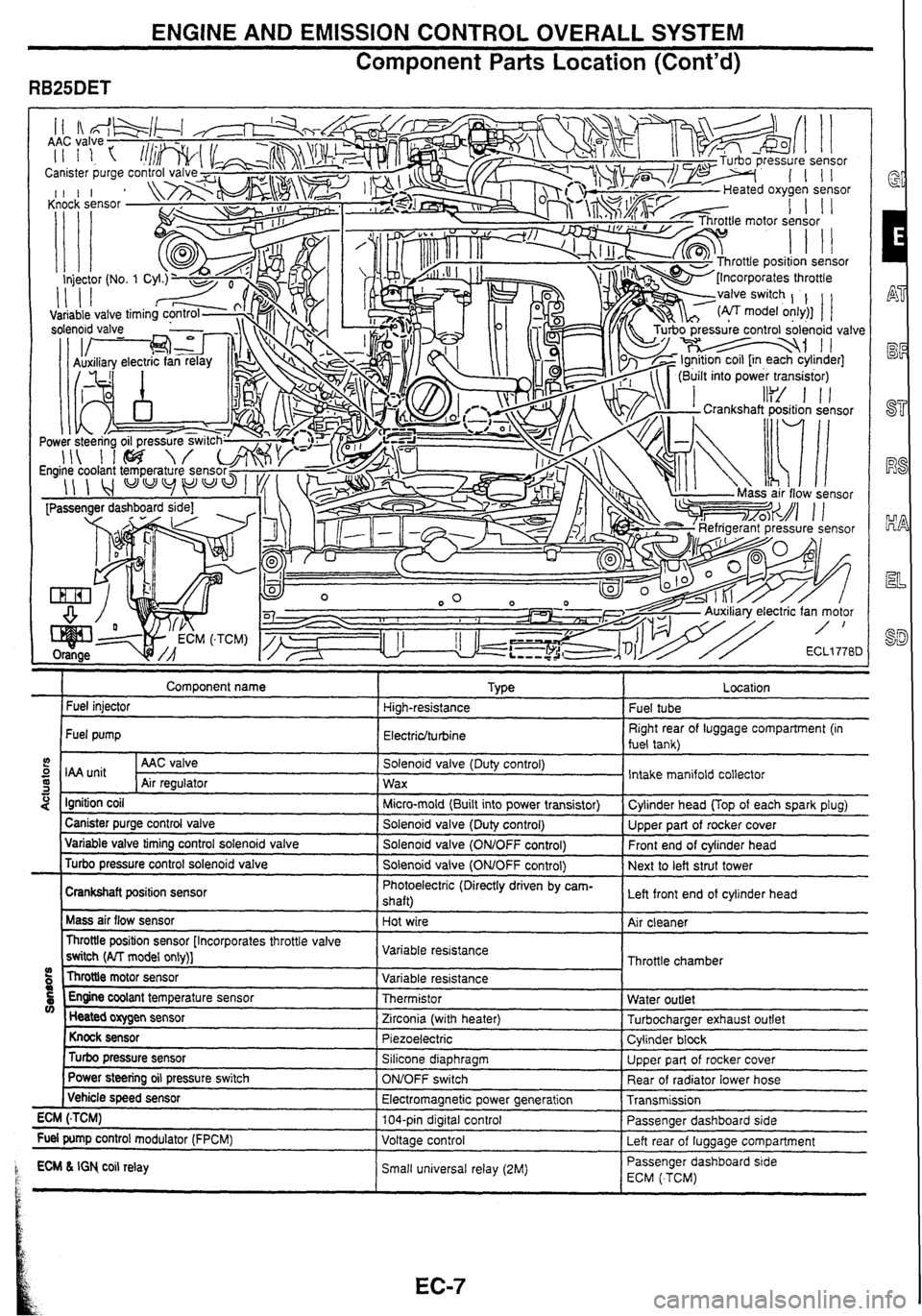
Component
Parts Location (Cont'd)
" . . ., . .7
Comoonent name I TVLE a r Fuel injector High-resistance
Fuel pump
Electriclturbine
5 I unit I AAC valve I Solenoid valve (Duty control)
S Air reoulator 1 wax -1 I " - . -.
4 Ignition coil I Micro-mold (Built into power transistor)
I Canister purge control valve I Solenoid valve (Dutv control) ---- - Variable valve timing control solenold valve I Solenold valve (ONtOFF control)
Turbo pressure control solenoid valve
I Solenoid valve (OMOFF control)
Crankshaft position sensor Photoelectric
(Directly driven by cam-
shaft)
Mass air flow sensor
Hot wire
Throttle position sensor [Incorporates throttle valve
switch
(AlT model only)] Variable
resistance
Throttle motor sensor
09 Variable resistance
5 Engine coolant temperature sensor Thermistor V) Heated oxygen sensor
Zirconia (with heater)
Knock sensor Piezoelectric
Turbo pressure sensor Silicone diaphragm
Power
steering oil pressure switch
ONJOFF switch
( Vehicle speed sensor
Electromagnetic power generation
ECM
(.TCM) 104-pin digital control
Fuel pump control modulator (FPCM)
Voltage control
1 ECM L IGN co~l relay Small un~versal relay (2M) P t
.
Fuel tube
Right rear of luggage compartment (in
fuel tank)
Intake manifold collector
Cvlinder head
UOD of each soark olua)
Upper part of rocker cover
Front end of cylinder head
Next to left strut tower
Left front end of cylinder head
Air cleaner
Throttle chamber
Water outlet
Turbocharaer exhaust outlet
Cylinder
block
Upper part of rocker cover
Rear of radiator lower hose
Transmission
Passenger dashboard side
Left rear of
luaaaae comoartment
-- Passenger dashboard s~de
ECM ( TCM)
Page 18 of 230

ENGINE AND EMISSION CONTROL OVERALL SYSTEM
Circuit Diagram
RB20DE (UB).MTT, RB25DE, RB25DET.MTT MODELS
Fan motor
Auxtliary
electric
Ian
relay
-
Alr cmdll~oner compressor
Arr
conduoner
relay
14
Y Mallunct~on indcator lamp A 17
26 $7 = Power steenng 011
pressure sw~icr.
I
23
43 Engine Want
temwrature sensor B.
Tachometer drive signal Check connmr
To rear defogger relay
/ [RB2MWD TO starter motor *'""L'*" - > TO PNP switch
I TO Starter relay
[Except lor ' - RB25DE.4WDI
Page 19 of 230

ENGINE AND EMISSION CONTROL OVERALL SYSTEM
Circuit Diagram (Cont'd)
RB2ODE (UB).A/T, RB25DET.AfT MODELS
".--- , - TC rear de'ogger relay 4 49
T 176
. . .- . . . . . , ,. - . . . , 59 . : . Turbine
at -.. A sensor A
Overrun clutzh
. shdt ~lenwd valve k pressure detection switch
I' Sh:H control unit Droppins revstor 8 18 9 'S 10
Page 20 of 230
ENGINE AND EMISSION CONTROL OVERALL SYSTEM
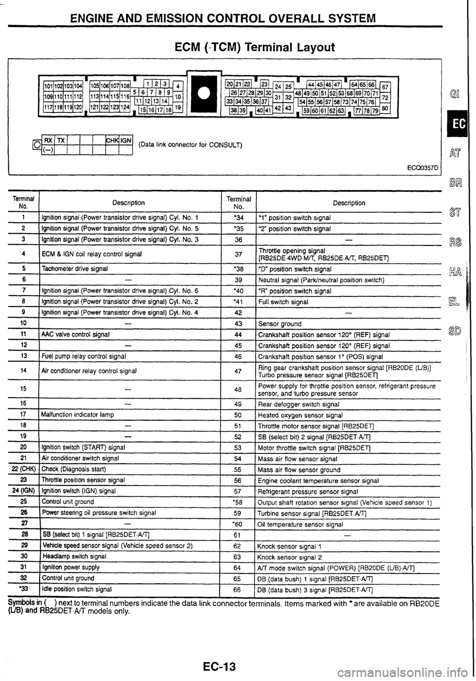
ECM (-TCM) Terminal Layout
I GY
CH~'GN- (Data link connector for CONSULT)
Terminal NO.
1 Description Terminal 1 No I Description - - 1 I lgnition
signal (Power transistor drrve signal) Cyl. No. 1 1 '34 Iu1" positron switch signal -- ---- 2 1 Ignition signal (Power transistor drive signal) Cyl. No. 5 1 '35 1 ''2" posifion switch signal - - 3 1 Ignition signal (Power transistor drive signal) Cyl. No. 3 1 36 1 -
4 I ECM 6 IGN coil relay control signal 1 37 1 Throttle opening signal
[RB25DE.4WD,M/TS RB25DE.m RB25DEll
- - - -- - - - - 8 ( Ignition signal (Power transistor drive signal) Cyl. No. 2 ( '41 1 f-k swltch signal
5
6
7
11 ( AAC valve control signal ( 44 1 Crankshaft position sensor 120' (REF) signal
Tachometer
drive signal
-
Ignition signal (Power transistor drive signal) Cyl. No. 6
9
10
'38
39
'40
Ignition signal (Power transistor drive signal)
Cyl.
No. 4
-
12
13
"D" position switch signal
Neutral signal
(Parklneutral position switch)
"R" position switch signal
14
Symbols in ( ) next to terminal numbers indicate the data link connector terminals. Items marked with are available on RB20DE (UB) and RB25DET.m models only.
42
43
-
Fuel pump relay control signal
15
16
17
18
19
20 21
22 (CHK)
23
24 (IGN)
25
26
27
28
29
30
31
32
'33
- -
Sensor around
Air conditioner relay control signal 45
46
-
-
Malfunction indicator lamp
-
-
Ignition switch (START) signal
Air conditioner switch signal
Check (Diagnosis start)
Throttle position sensor signal
Ignition switch
(IGN) signal
Control unit ground
Power steering oil pressure switch signal
-
1 SB (select bit) 1 signal [RB25DET.A/Tl
1 Vehicle speed sensor signal (Vehicle speed sensor 2)
Headlamp switch signal
Ignition power supply
Control unit ground
Idle position switch signal Crankshaft
position sensor 120" (REF) signal
Crankshaft position sensor 1
" (POS) signal
47 Ring gear crankshaft position sensor signal [RB20DE (UB)]
Turbo pressure sensor signal
LRB25DEl-J
48
49
50
51
52
53
54
55
56
57
'58 59
'60 61
62
63
64
65
66 Power
supply for throttle position sensor, refrigerant pressure
sensor, and turbo pressure sensor
Rear defogger switch signal
Heated oxygen sensor signal
Throttle motor sensor signal [RB25DET]
SB
(select bit)
2 signal (RB25DET.ATJ
Motor throttle switch signal
[RB25DET]
Mass air flow sensor signal
Mass air flow sensor ground
Engine coolant temperature sensor signal
Refrigerant pressure sensor signal
Output shaft rotation sensor signal (Vehicle speed sensor 1)
Turbine sensor signal
[RB25DET.AlTj
Oil temperature sensor signal
Knock sensor signal
1
Knock sensor signal 2
PJT mode switch signal (POWER) [RB20DE (UB).A/Tl
DB (data bush) 1 signal [RB25DET.W
DB (data bush)
3 signal [RB25DET.W
Page 21 of 230
ENGINE AND EMISSION CONTROL OVERALL SYSTEM
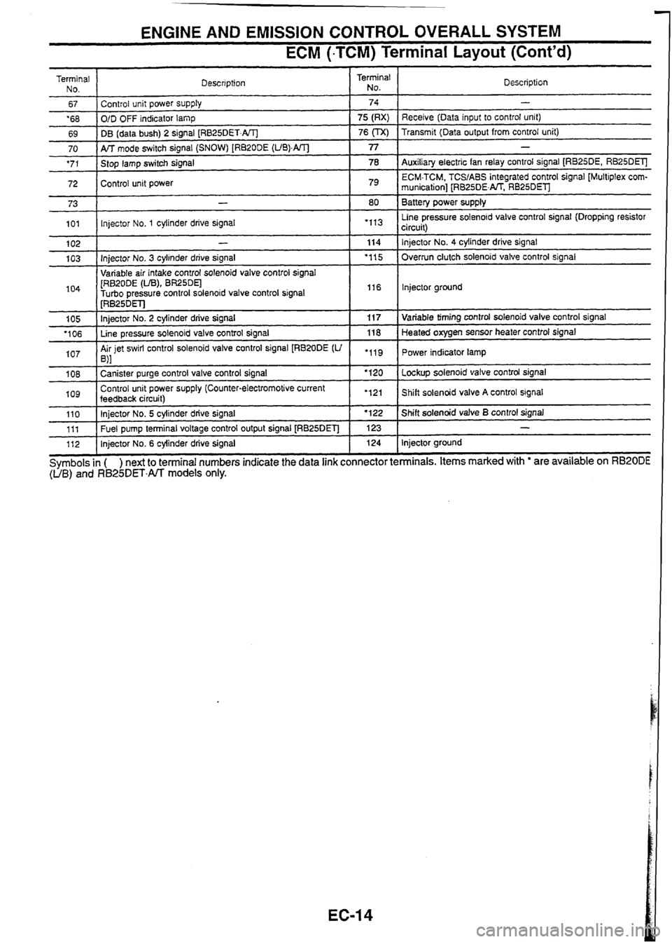
ECM (-TCM) Terminal Layout (Cont'd)
Terminal
No.
67
'68
69 Description
70
'71
72 I
Control unit power supply
O/D OFF indicator
lamp
DB (data bush) 2 signal
[RB25DET.AIT]
73
101
104
1 [RB~ODE (LIB), BR25DEl -
Turbo oressure control solenoid valve control signal I I16 I lnjector ground
Terminal
No.
AK mode switch signal (SNOW) [RB20DE (UB).AIT]
Stop lamp switch signal
Control unit power
102
103 Description
74
75 (RX)
76
(TX)
1 I . .
-
Receive (Data input to control unit)
Transmit (Data output from control unit)
77
78
79
-
Injector No. 3 cylinder drive signal
Variable air intake control solenoid valve control
sianal
105
'106
107
-
Auxiliary electric fan relay control signal [RB25DE, RB25DElJ
ECM.TCM. TCSIABS integrated control signal [Multiplex
com-
munication] [RB25DENT. RB25DEl
Battery power supply
Line pressure solenoid valve control signal (Dropping resistor
circuit)
-
lnjector No. 1 cylinder drive signal
1 08
log
80
"I3
114
'1 15
[RB~~DET]
Injector No. 2 cylinder drive signal
Line pressure solenoid valve control signal
Air jet swirl control solenoid valve control signal
[RB20DE
(U ,\I
110 111
112 Injector No.
4 cylinder
drive signal
Overrun clutch solenoid valve control signal
"11
Canister purge control valve control signal
Control unit power supply (Counter-electromotive current
feedback
circuit) 11
7
118
.119
Symbols
in ( ) next to terminal numbers indicate the data link connector terminals. Items marked with ' are available on RB20DE (UB) and R825DET.All models only.
Injector No. 5 cylinder drive signal
Fuel pump terminal voltage control output signal
[RB25DET]
Injector No. 6 cylinder drive signal Variable
timing control solenoid valve control signal
Heated oxygen sensor heater control signal
Power indicator lamp
'120
'121 Lockup solenoid valve control signal
Shift solenoid valve
A control signal I '122
123 124 Shift solenoid valve B control signal
-
Injector ground
Page 22 of 230
TROUBLE DIAGNOSES --- - - - -- -- - -
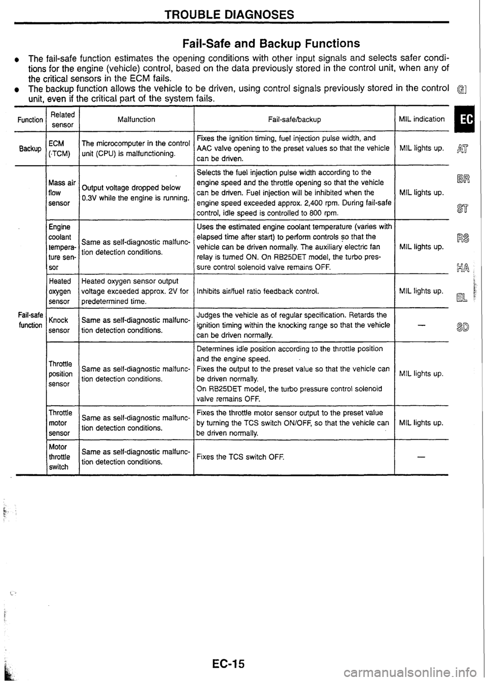
Fail-safe and Backup Functions
0 The fail-safe function estimates the opening conditions with other input signals and selects safer condi-
tions for the engine (vehicle) control, based on the data previously stored in the control unit, when any of
the critical sensors in the
ECM fails.
The backup function allows the vehicle to be driven, using control signals previously stored in the control G]
unit, even if the critical part of the system fails.
MIL indication
I
Related
sensor
Function
Backup Malfunction
Fail-safehacku p
Fixes the ignition timing, fuel injection pulse width, and
AAC valve opening to the preset values so that the vehicle
can be driven.
ECM
(-TCM)
Mass air
flow
sensor
Engine
coolant
tempera- ture sen-
sor The
microcomputer in the control
unit (CPU) is malfunctioning. MIL lights
up. A'
-- --
Selects the fuel injection pulse width according to the
engine speed and the throttle opening so that the vehicle
can be driven. Fuel injection will be inhibited when the
engine speed exceeded approx.
2,400 rpm. During fail-safe
control, idle speed is controlled to 800
rpm.
Uses the estimated engine coolant temperature (varies with
elapsed time after start) to perform controls so that the
vehicle can be driven normally. The auxiliary electric fan
relay is turned ON. On
RB25DET
model, the turbo pres-
sure control solenoid valve remains OFF.
%R
MIL lights up.
ST
Output voltage dropped below
0.3V while the engine is running.
MIL lights up.
R8 Same as self-diagnostic malfunc-
tion detection conditions.
Heated
owen
sensor Heated oxygen sensor output
voltage exceeded approx.
2V for
predetermined time.
Same as self-diagnostic malfunc-
tion detection conditions. MIL
lights up. d d Inhibits aidfuel ratio feedback control.
Judges the vehicle as of regular specification. Retards the
ignition timing within the knocking range so that the vehicle
can be driven normally.
Determines idle position according to the throttle position
and the engine speed.
Fixes the output to the preset value so that the vehicle can
be driven normally.
On
RB25DET model, the turbo pressure control solenoid
valve remains OFF.
Fail-safe
function Knock
sensor
Throttle position
sensor Same
as self-diagnostic malfunc-
tion detection conditions. MIL
lights up.
Throttle motor
sensor
--
Fixes the throttle motor sensor output to the preset value
by turning the TCS switch
ONIOFF, so that the vehicle can
Same
as self-diagnostic malfunc-
tion detection conditions. MIL
lights up.
be driven normally.
Motor
throttle
switch Same
as
self-diag
nostic
malfunc-
tion detection conditions. Fixes the
TCS switch OFF.
t.. -
Page 30 of 230
![NISSAN GT-R 1998 Service Manual
TROUBLE DIAGNOSES .
CONSULT (Contd)
Monitored item
[Unit] signals Description
Remarks
INJ
PULSE [msec]
I
When the engine is stopped, a certain
computed value is indicated. lndicates NISSAN GT-R 1998 Service Manual
TROUBLE DIAGNOSES .
CONSULT (Contd)
Monitored item
[Unit] signals Description
Remarks
INJ
PULSE [msec]
I
When the engine is stopped, a certain
computed value is indicated. lndicates](/img/5/57354/w960_57354-29.png)
TROUBLE DIAGNOSES .
CONSULT (Cont'd)
Monitored item
[Unit] signals Description
Remarks
INJ
PULSE [msec]
I
When the engine is stopped, a certain
computed value is indicated. lndicates the actual fuel injection pulse
width compensated by ECM according to
the input
siqnals.
IGN TIMING [BTDC]
I lo
lndicates the ignition timing computed by ECM according to the input signals. When the engine is stopped, a certain
value is indicated.
IACV-AACN
I%]
I lo
lndicates IACV-AACN control value com-
puted by ECM according to the input sig-
nals.
PURG VOL CN
[ONIOFF dutyj lndicates the EVAP canister purge vol-
ume control valve computed by the ECM according to the input signals. The opening becomes larger as the
value increases.
AIF
ALPHA [%]
- The mean value of the air-fuel ratio feed-
back correction factor per cycle is indi-
cated. -- - When the engine is stopped, a certain
value is indicated.
This data also includes the data for the
air-fuel ratio learning control.
AIR COND
RLY [ONIOFF] The air conditioner relay control condition
(determined by ECM according to the
input signal) is indicated.
-- - - Indicates the fuel pump relay control con-
dition determined by ECM according to
the input signals.
The control condition of the intake valve
timing control solenoid valve is indicated.
ON
... Intake valve timing control is oper-
ating. OFF
... lntake valve timing control is not
operating.
VlAS
SN [ONIOFF] RB20DE (UB), RB25DE
Control conditions computed by ECM Solenoid valve activated: ON Solenoid valve not activated: OFF
SWRL CONT SN
[ON/OFF]
0 RB20DE (UB)
COOLING FAN
[HVLOW/O FF] RB25DE, RB25DET
The control condition of the cooling fan
(determined by ECM according to the
input signal) is indicated.
HI
... High speed operation LOW ... Low speed operation
OFF ... Stop
TURBO CONT
SN 0 RB25DET Control conditions computed by ECM
Solenoid valve activated: ON Solenoid valve not activated: OFF
PD PRESSURE
SENSOR M Refrigerant pressure sensor output volt-
age Approx. 0.36V min.
(Varies with air conditioner refrigerant
pressure)
, VOLTAGE Voltage measured by the voltage probe.
Pulse width, frequency or duty cycle
measured by the pulse probe. Only "#" is displayed if item is unable to
be measured.
r Figures with "#"s are temporary ones.
They are the same figures as an actual
piece of data which was just previously
measured.
Page 31 of 230
TROUBLE DIAGNOSES
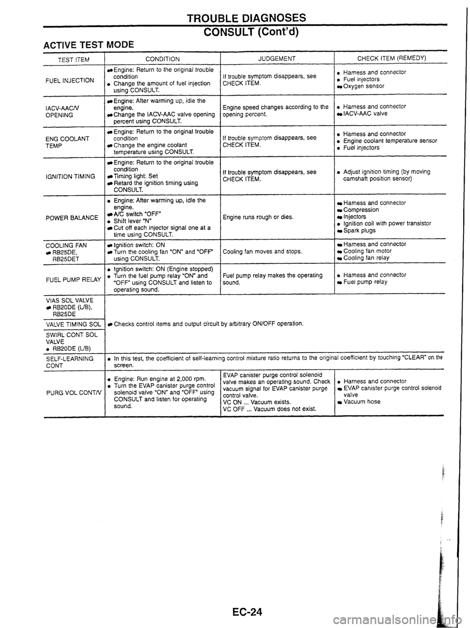
CONSULT (Cont'd)
ACTIVE TEST MODE
INJECTION I . CCohArthe amount of fuel injection
TEST ITEM
CONDITION
Engine: Return
to the original trouble
- I . Engine: After warming up, idle the
IACV-AACN
OPENING
ENG COOLANT
TEMP
IGNITION TIMING
US~~~CONSULT.
Engine: After warming up, idle the
engine.
Change the IACV-AAC valve opening
percent using CONSULT.
Engine: Return to the original trouble
conditioo
Change the engine coolant
temperature using CONSULT.
Engine: Return to the original trouble
condition
Timing light: Set Retard the ignition timing using CONSULT.
POWER BALANCE engine. A/C switch "OFF . Shift lever uNn
COOLING
FAN RB25DE, RB25DET
FUEL PUMP RELAY
VlAS SOL VALVE RB20DE (UB), RB25DE
JUDGEMENT
Cut off each injector signal one at a
time using CONSULT.
Ignition switch: ON Turn the cooling fan "ON" and "OFF
using CONSULT.
0 lgnition switch: ON (Engine stopped) . Turn the fuel pump relay "ON" and
"OFF using CONSULT and listen to
operating sound. CHECK
ITEM (REMEDY)
If trouble symptom disappears, see
CHECK ITEM. : ~,"~~,,,~scOnnectOr Oxygen sensor
Engine speed changes according to the
opening percent.
. Harness and connector IACV-AAC valve
If trouble
symp:orn disappears, see
CHECK ITEM. : Sensor 0 Fuel injectors
If trouble symptom disappears, see
CHECK ITEM. 0 Adjust ignition timing (by moving
camshaft position sensor)
Engine runs rough or dies.
Harness and connector Compression Injectors 0 lgnition coil with power transistor Spark plugs
Cooling fan moves and stops.
Hamess and connector Cooling fan motor Cooling fan relay
Fuel pump relay makes the operating
sound.
. Harness and connector Fuel pump relay
VALVE
TIMING
SOL
SWIRL CONT SOL
VALVE
0 RB20DE (UB)
SELF-LEARNING
CONT
PURG VOL CONTN
Checks control items and output circuit by arbitrary ON/OFF operation.
. In this test, the coefficient of self-learning control mixture ratio returns to the original coefficient by touching "CLEAR" on the
screen.
. Harness and connector EVAP canister purge control solenoid
valve
Vacuum hose
0 Engine: Run engine at 2,000 rpm. . Turn the EV~P canister purge control solenoid valve and using CONSULT and listen for operating
sound. EVAP
canister purge control solenoid
valve makes an operating sound. Check
vacuum signal for EVAP canister purge ~~~~~~a'cuum exists. VC OFF ... Vacuum does not exist.