water pump NISSAN GT-R 1998 Service Manual
[x] Cancel search | Manufacturer: NISSAN, Model Year: 1998, Model line: GT-R, Model: NISSAN GT-R 1998Pages: 230, PDF Size: 12.66 MB
Page 13 of 230

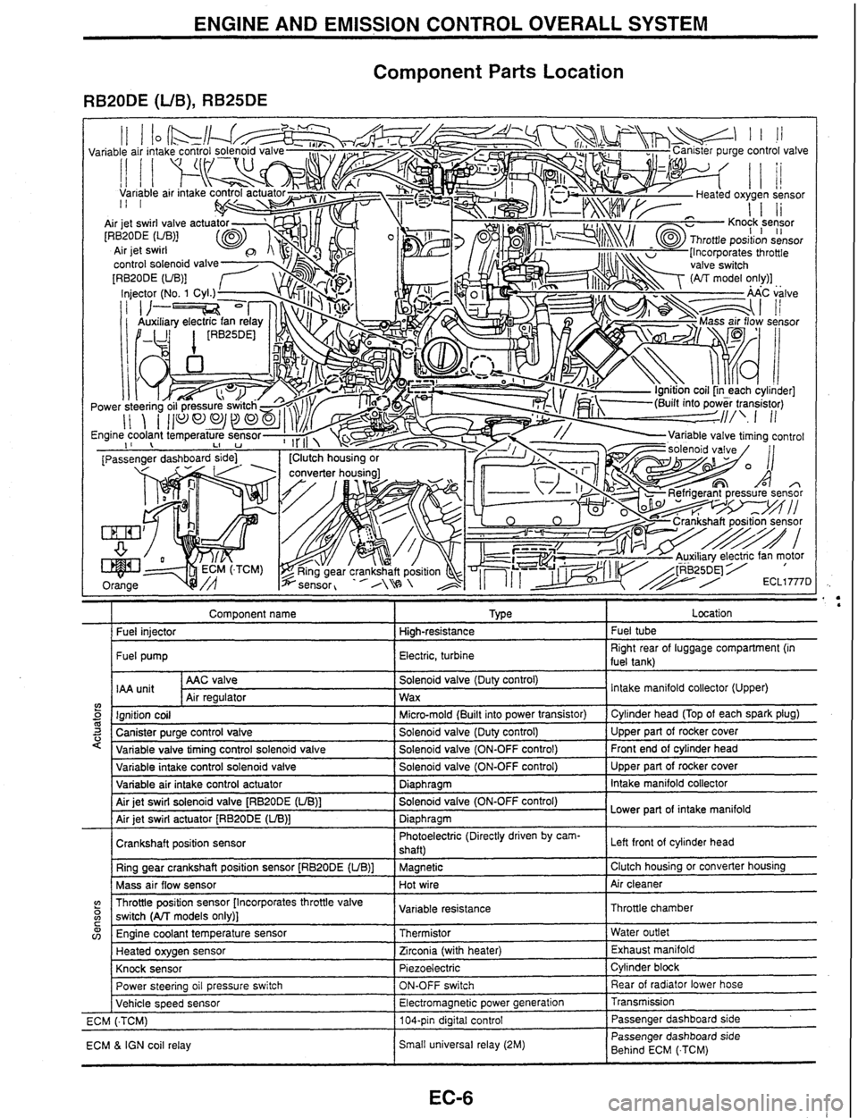
ENGINE AND EMISSION CONTROL OVERALL SYSTEM
Component Parts Location
RB20DE (UB), RB25DE
Component name I Type I Location
I Fuel iniector I Hiah-resistance I Fuel tube
I Fuel pump I Electric, turbine I Right rear of luggage compartment (in
fuel tank)
AAC valve
IAA
unit Air reaulator
5 m 3 '
Solenoid valve (Duty control)
Wax
variable intake control solenoid valve
Variable air intake control actuator
Air jet swirl solenoid valve
[RBPODE (UB)]
Air jet swirl actuator
[RB20DE (LIB)]
Crankshaft position sensor Ring gear crankshaft position sensor
[RB20DE (UB)]
Mass air flow sensor Intake
manifold collector (Upper)
Ignition coil
Canister purge control valve
Variable valve tirnina control
solenoid valve
(? o C
Solenoid valve (ON-OFF control)
Diaphragm
Solenoid valve (ON-OFF control)
Diaphragm Photoelectric (Directly driven by cam-
shaft)
Magnetic
Hot wire
w v,
Micro-mold (Built into power transistor)
Solenoid valve (Duty control)
Solenoid valve (ON-OFF control) Upper part of rocker cover
Intake manifold collector
Lower part of intake manifold
Left front
of cylinder head
Clutch housing or converter housing
Air cleaner
Throttle position sensor [Incorporates throttle valve
switch
(All models only)]
Power steering oil pressure switch
Vehicle speed sensor
ECM
(.TCM)
ECM
& IGN coil relay Cylinder head
(Top of each spark plug)
Upper part of rocker cover
Front end of cylinder head
Engine coolant temperature sensor
Heated oxygen sensor
Knock sensor Variable
resistance
ON-OFF switch
Electromagnetic power generation
104-pin digital control
Small universal relay (2M) Throttle chamber
Thermistor
Zirconia (with heater)
Piezoelectric Rear of radiator lower hose
Transmission Passenger dashboard side
Passenger dashboard side
Behind ECM
(.TCM) Water
outlet
Exhaust manifold
Cylinder block
Page 14 of 230

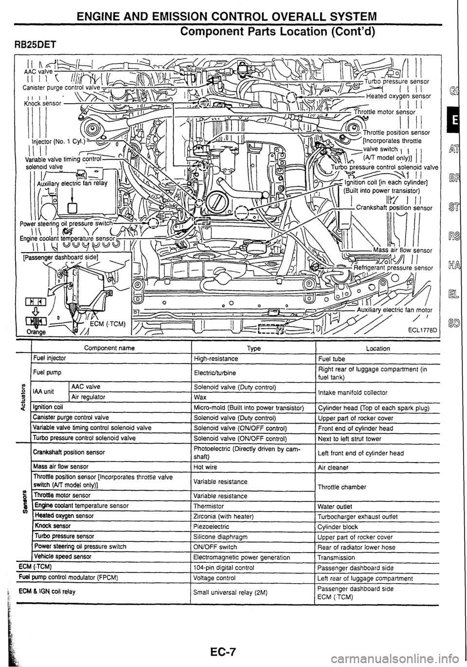
ENGINE AND EMISSION CONTROL OVERALL SYSTEM
Component
Parts Location (Cont'd)
" . . ., . .7
Comoonent name I TVLE a r Fuel injector High-resistance
Fuel pump
Electriclturbine
5 I unit I AAC valve I Solenoid valve (Duty control)
S Air reoulator 1 wax -1 I " - . -.
4 Ignition coil I Micro-mold (Built into power transistor)
I Canister purge control valve I Solenoid valve (Dutv control) ---- - Variable valve timing control solenold valve I Solenold valve (ONtOFF control)
Turbo pressure control solenoid valve
I Solenoid valve (OMOFF control)
Crankshaft position sensor Photoelectric
(Directly driven by cam-
shaft)
Mass air flow sensor
Hot wire
Throttle position sensor [Incorporates throttle valve
switch
(AlT model only)] Variable
resistance
Throttle motor sensor
09 Variable resistance
5 Engine coolant temperature sensor Thermistor V) Heated oxygen sensor
Zirconia (with heater)
Knock sensor Piezoelectric
Turbo pressure sensor Silicone diaphragm
Power
steering oil pressure switch
ONJOFF switch
( Vehicle speed sensor
Electromagnetic power generation
ECM
(.TCM) 104-pin digital control
Fuel pump control modulator (FPCM)
Voltage control
1 ECM L IGN co~l relay Small un~versal relay (2M) P t
.
Fuel tube
Right rear of luggage compartment (in
fuel tank)
Intake manifold collector
Cvlinder head
UOD of each soark olua)
Upper part of rocker cover
Front end of cylinder head
Next to left strut tower
Left front end of cylinder head
Air cleaner
Throttle chamber
Water outlet
Turbocharaer exhaust outlet
Cylinder
block
Upper part of rocker cover
Rear of radiator lower hose
Transmission
Passenger dashboard side
Left rear of
luaaaae comoartment
-- Passenger dashboard s~de
ECM ( TCM)
Page 33 of 230

TROUBLE DIAGNOSES t i
CONSULT (Cont'd) i
FUNCTION TEST MODE
CHECK ITEM (REMEDY)
FUNCTION
TEST
ITEM JUDGEMENT
CONDITION
lgnition switch: ON
(Engine stopped)
Displays the results of on board
diagnostic system.
SELF-DIAG
RESULTS Objective
system
--
ignition switch: ON
(Engine stopped)
Throttle position sensor circuit is
tested when throttle is opened and
closed fully. ("IDLE POSITION" is
the test item name for the vehicles
in which idle is selected by throttle
position sensor.) Harness and connector
Throttle position sensor (Closed
throttle position)
Throttle position sensor (Closed
throttle position) adjustment
Throttle linkage
Venfy operation in DATA
MONITOR mode.
Throttle
valve:
opened OFF
ON
CLOSED THROTTLE
POSl Throttle valve:
closed
lgnition switch: ON
(Engine stopped)
Throttle position sensor circuit is
tested when throttle is opened and
closed fully.
Harness and connector
Throttle position sensor
Throttle position sensor
adjustment
Throttle linkage
Verify operation in DATA
MONITOR mode.
Range
(Throttle
valve fully opened
- Throttle valve
fully closed) More
than 3.0V THROTTLE POSl
SEN CKT
lgnition switch: ON
(Engine stopped)
Neutral position switch circuit is
tested when shift lever is
manipulated.
lgnition switch: ON
(Engine stopped)
Fuel pump circuit is tested by
checking the pulsation in fuel
pressure when fuel tube is
pinched. Out of
N/P
positions OFF
Harness
and connector
Neutral position switch
Linkage adjustment
PARWNEUT POSl SW CKT
In
N/P positions
Harness and connector
Fuel pump
Fuel pump relay
Fuel filter clogging
Fuel level
There
is pressure pulsation on
the fuel feed hose.
FUEL PUMP
CIRCUIT
--
The valve timing control system is
diagnosed by checking for
operating sound of the solenoid
valve.
lgnition switch: ON
(Engine stopped)
Cooling fan circuit is tested when
cooling fan is rotated.
VALVE
TIMING
SN
CKT
Harness and connector
Cooling fan motor
Cooling fan relay
COOLING
FAN
CIRCUIT RB25DE, RB25DET
The cooling fan rotates and
stops every
3 seconds.
lgnition switch: ON -+ START
Start signal circuit is tested when
engine is started by operating the
starter. Battery voltage and water
temperature before cranking, and
average battery voltage, mass air
flow sensor output voltage and
cranking speed during cranking
are displayed.
Harness and connector
lgnition switch
START
SIGNAL
CIRCUIT Start
signal: OFF 3 ON
Page 203 of 230

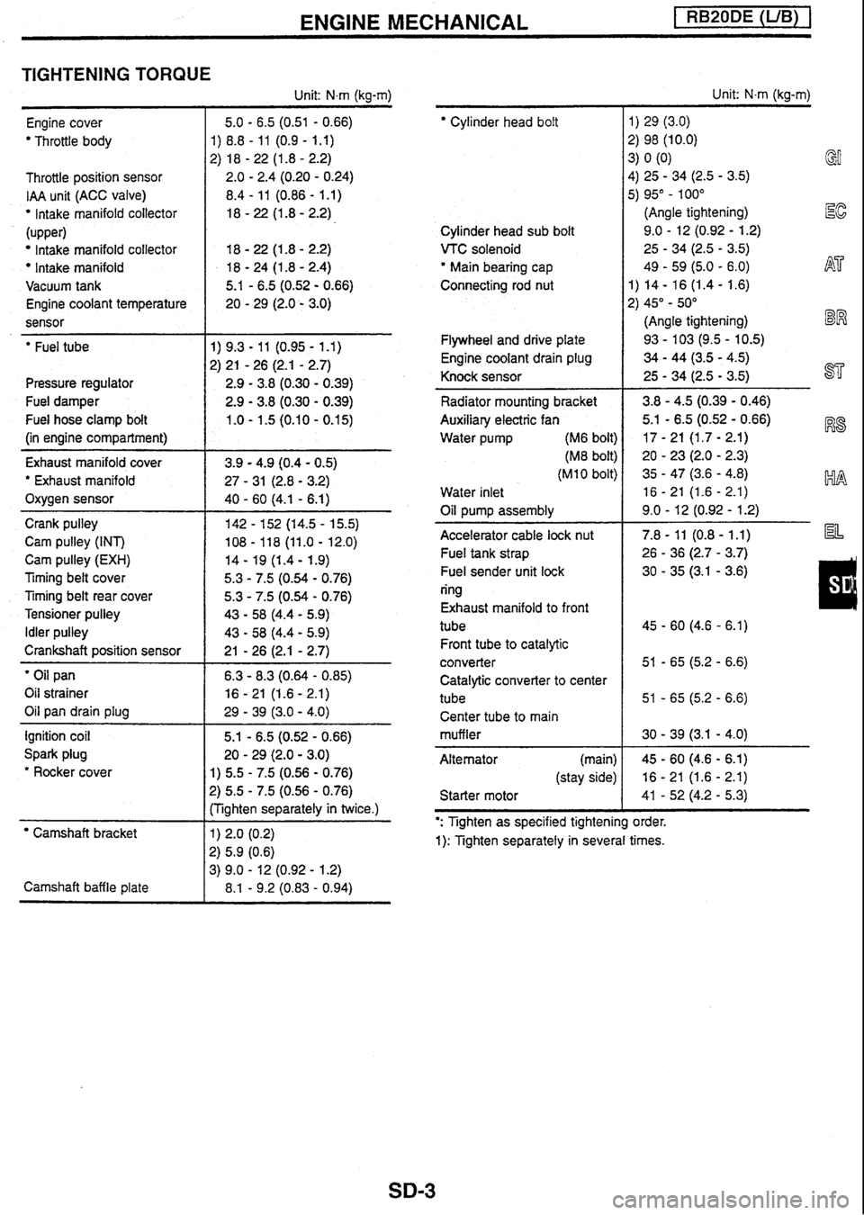
ENGINE MECHANICAL [ RB20DE (UB) 1
TIGHTENING TORQUE
Unit: N.m (kg-m)
Engine cover
Throttle body
Throttle position sensor
IAA unit (ACC valve)
lntake manifold collector
(upper)
Intake manifold collector
Intake manifold
Vacuum tank
Engine coolant temperature
sensor
- --
' Fuel tube
Pressure regulator
Fuel damper
Fuel hose clamp bolt
(in engine compartment)
Exhaust manifold cover
' Exhaust manifold
Oxygen sensor
Crank pulley
Cam pulley (INT)
Cam pulley
(EXH)
Timing belt cover
Timing belt rear cover
Tensioner pulley
Idler pulley
Crankshaft position sensor
' Oil pan
Oil strainer
Oil pan drain plug
ignition coil
Spark plug
* Rocker cover
Camshaft bracket
Camshaft baffle plate 5.1
- 6.5 (0.52 - 0.66)
20
- 29 (2.0 - 3.0)
1) 5.5 - 7.5 (0.56 - 0.76)
?) 5.5 - 7.5 (0.56 - 0.76)
:Tighten separately in twice.)
Cylinder head bolt
Cylinder head sub bolt
VTC solenoid
' Main bearing cap
Connecting rod nut
Flywheel and drive plate
Engine coolant drain plug
Knock sensor
Radiator mounting bracket
Auxiliary electric fan
Water pump (M6 bolt)
(M8 bolt)
(MI 0 bolt)
Water inlet
Oil pump assembly
Accelerator cable
lock nut
Fuel tank strap
Fuel sender unit lock
ring
Exhaust manifold to front
tube Front tube to catalytic
converter Catalytic converter to cent
tube Center tube to main
muffler
Alternator (main)
(stay side)
Starter motor Unit:
N-m (kg-m)
1)
29 (3.0)
2) 98 (10.0)
3)
0
(0)
4) 25
- 34 (2.5 - 3.5) GI
5) 95" - 100"
(Angle tightening)
Ec
9.0 - 12 (0.92 - 1.2)
25
- 34 (2.5 - 3.5)
49
- 59 (5.0 - 6.0) h$7'
1) 14 - 16 (1.4 - 1.6)
2) 45"
- 50"
(Angle tightening)
BW
93 - 103 (9.5 - 10.5)
34 - 44 (3.5 - 4.5)
25
- 34 (2.5 - 3.5) ST
': Tighten as specified tightening order.
1): Tighten separately in several times.
Page 205 of 230

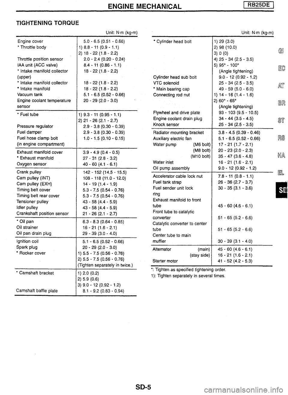
ENGINE MECHANICAL
TIGHTENING TORQUE
Engine cover
' Throttle body
Throttle position sensor
IAA unit (ACC valve)
' Intake manifold collector
(upper)
' Intake manifold collector
Intake manifold
Vacuum tank
Engine coolant temperature
sensor
' Fuel tube
Pressure regulator
Fuel damper
Fuel hose clamp bolt
(in engine compartment)
Exhaust manifold cover
Exhaust manifold
Oxygen sensor
Crank pulley
Cam pulley (INT)
Cam pulley
(EXH)
Timing belt cover
Ttming belt rear cover
Tensioner pulley
Idler pulley
Crankshaft position sensor
' Oil pan
Oil strainer
Oil pan drain plug
Ignition coil
Spark plug
Rocker cover
* Camshaft bracket
Camshaft baffle plate Unit:
Nm (kg-m)
5.0
- 6.5 (0.51 - 0.66)
1) 8.8
- 11 (0.9 - 1.1)
2) 18
- 22 (1.8 - 2.2)
2.0
- 2.4 (0.20 - 0.24)
8.4
- 11 (0.86 - 1 .I)
18
- 22 (1.8 - 2.2)
5.1
- 6.5 (0.52 - 0.66)
20
- 29 (2.0 - 3.0)
1) 5.5 - 7.5 (0.56 - 0.76)
2) 5.5 - 7.5 (0.56 - 0.76)
:Tighten separately in twice.)
Cylinder head bolt
Cylinder head sub bolt
VTC solenoid
Main bearing cap
Connecting rod nut
Flywheel and drive plate
Engine coolant drain plug
Knock sensor
Radiator mounting bracket
Auxiliary electric fan
Water pump
(M6 bolt)
(M8 bolt)
(M 1 0 bolt)
Water inlet
Oil pump assembly
-
Accelerator cable lock nut
Fuel tank strap
Fuel sender unit lock
ring
Exhaust manifold to front
tube
Front tube to catalytic
converter
Catalytic converter to center
tube Center tube to main
muffler
Alternator (main)
(stay side)
Starter motor Unit:
N.m (kg-m)
1) 29 (3.0)
2) 98 (10.0) 3) 0 (0)
@
4)
25 - 34 (2.5 - 3.5)
5) 95" - 100"
(Angle tightening)
E
9.0 - 12 (0.92 - 1.2)
25
- 34 (2.5 - 3.5) j$? 49 - 59 (5.0 - 6.0)
1) 14- 16
(1.4- 1.6)
2) 60"
- 65" BR
(Angle tightening)
93
- 103 (9.5 - 10.5)
34 - 44 (3.5 - 4.5)
25
- 34 (2.5 - 3.5) a=
': Tighten as specified tightening order.
1): Tighten separately in several times.
Page 207 of 230

ENGINE MECHANICAL pEZBq
TIGHTENING TORQUE
Engine cover
' Throttle body
Throttle position sensor
IAA unit
(ACC valve)
' Intake manifold collector
* Intake manifold
Engine coolant temperature
sensor
' Fuel tube
Pressure regulator
Fuel damper
Fuel hose clamp bolt
(in engine compartment)
Turbocharger Oil tube
Water tube (block side)
(turbocharger side)
Oxygen sensor
Exhaust manifold cover
' Exhaust manifold
Crank pulley
Cam pulley (INT)
Cam pulley
(EXH)
Timing belt cover
Timing belt rear cover
Tensioner pulley
Idler pulley
Crankshaft position sensor
' Oil pan
Oil strainer
Oil pan drain plug
Ignition coil
Spark plug
' Rocker cover
' Camshaft bracket
Camshaft baffle plate Unit:
N.m (kg-m)
5.0
- 6.5 (0.51 - 0.66)
1)
8.8
- 11 (0.9 - 1.1)
2)
18
- 22 (1 -8 - 2.2)
2.0
- 2.4 (0.20 - 0.24)
8.4
- 11 (0.86 - 1.1)
18
- 22 (1.8 - 2.2)
18
- 22 (1 -8 - 2.2)
20
- 29 (2.0 - 3.0)
5.1
- 6.5 (0.52 - 0.66)
20
- 29 (2.0 - 3.0)
1) 5.5
- 7.5 (0.56 - 0.76)
2) 5.5 - 7.5 (0.56 - 0.76)
(Tighten separately in twice.)
' Cylinder head boit
Cylinder head sub bolt
VTC solenoid
" Main bearing cap
Connecting rod
nut
Oil jet
Flywheel and drive plate
Engine coolant drain plug
Knock sensor
Radiator mounting bracket
Auxiliary electric fan
Water pump (M6 bolt)
(M8 bolt)
(MI
0 bolt)
Water inlet
Oil pump assembly
Accelerator cable lock nut
Fuel tank strap
Fuel sender unit lock
ring
Exhaust manifold to front
tube
Front tube to catalytic
converter
Catalytic converter to center
tube
Center tube to main
muffler
Alternator (main)
(stay side)
Starter motor Unit:
N.m (kg-m)
1) 29 (3.0)
2) 98 (10.0)
3) 0 (0)
4) 25 - 34 (2.5 - 3.5)
5) 95"
- 100"
(Angle tightening)
I%
9.0 - 12 (0.92 - 1.2)
25
- 34 (2.5 - 3.5)
49
- 59 (5.0 - 6.0) AT
1) 14 - 16 (1.4 - 1.6)
2) 60" - 65"
(Angle tightening) BR
30 - 40 (3.1 - 4.1)
93
- 103 (9.5 - 10.5)
34 - 44 (3.5 - 4.5) ST
25 - 34 (2.5 - 3.5)
3.8
- 4.5 (0.39 - 0.46) I%$
5.1 - 6.5 (0.52 - 0.66)
17
- 21 (1.7 - 2.1)
20
- 23 (2.0 - 2.3) kIA
35 - 47 (3.6 - 4.8)
16
- 21 (1.6 - 2.1)
9.0
- 12 (0.92 - 1.2) a=
': Tighten as specified tightening order.
1): Tighten separately in several times.