light NISSAN GT-R 2015 R35 Multi Function Display Owners Manual
[x] Cancel search | Manufacturer: NISSAN, Model Year: 2015, Model line: GT-R, Model: NISSAN GT-R 2015 R35Pages: 298, PDF Size: 11.39 MB
Page 223 of 298
![NISSAN GT-R 2015 R35 Multi Function Display Owners Manual 8-24Voice recognition
INFO:
With [Continuous Learning] set to on, the
system does not go back to the command
list screen, allowing to continue voice
command learning by the system.
12. If the system h NISSAN GT-R 2015 R35 Multi Function Display Owners Manual 8-24Voice recognition
INFO:
With [Continuous Learning] set to on, the
system does not go back to the command
list screen, allowing to continue voice
command learning by the system.
12. If the system h](/img/5/423/w960_423-222.png)
8-24Voice recognition
INFO:
With [Continuous Learning] set to on, the
system does not go back to the command
list screen, allowing to continue voice
command learning by the system.
12. If the system has learned the command correctly, “None” will change to “Stored”.
Editing registered items
It is possible to edit user names and select
learning function settings.
1. Push
2. Highlight [Others] and push
3. Highlight [Voice Recognition] and push
4. Highlight [Speaker Adaptation] and push
5. Highlight a user to edit, and push
6. Highlight [Setting] and push
7. Highlight an item to edit, and push
Setting items
.[Edit User Name]:
Edit the user name.
.[Delete Voice Data]:Reset the user voice that the voice
recognition system has learned.
.[Continuous Learning]:Have the system learn the voice com-
mands of the user in succession, without
selecting commands one by one.
VOICE COMMAND EXAMPLES
To use the voice recognition function, speaking
one command is sometimes sufficient, but at
other times it is necessary to speak two or more
commands. As examples, some additional basic
operations by voice commands are described
here.
Example 1: Switching map to 2D
(Plan View) mode
1. Push <>located on the steering wheel.
2. The system announces, “Please say a command”.
Page 233 of 298
9-6Monitor system
.The displayed line will appear
slightly off to the right because the
rear view camera is not installed in
the rear center of the vehicle.
. The distance guide line and the
vehicle width guide line should be
used as a reference only when the
vehicle is on a level paved surface.
The distance viewed on the monitor
is for reference only and may be
different than the actual distance
between the vehicle and displayed
objects.
. When backing up the vehicle up a
hill, objects viewed in the monitor
are further than they appear. When
backing up the vehicle down a hill,
objects viewed in the monitor are
closer than they appear. Use the
inside mirror or glance over your
shoulder to properly judge dis-
tances to other objects.
The vehicle width and predictive course
lines are wider than the actual width and
course.
1. Visually check that the parking space is safe before parking your vehicle.
2. The RearView of the vehicle is displayed on the screen
*Aas illustrated when the shift
lever is moved to the “R” (Reverse) position.
3. Slowly back up the vehicle, adjusting the steering wheel so that the predictive course
lines
*Benter the parking space*C.
4. Maneuver the steering wheel to make the vehicle width guide lines
*Dparallel to the
parking space
*Cwhile referring to the
predictive course lines.
Page 234 of 298
5. When the vehicle is parked in the spacecompletely, move the shift lever to the
“P”(Park) position and apply the parking
brake
OPERATING TIPS
.When the shift lever is shifted to the “R”
(Reverse) position, the monitor screen auto-
matically changes to the RearView Monitor
mode. However, the radio can be heard.
. It may take some time until the RearView
Monitor is displayed after the shift lever has
been shifted to “R” from another position or
to another position from “R”. Objects may be
distorted momentarily until the RearView
Monitor screen is displayed completely.
. When the temperature is extremely high or
low, the screen may not clearly display
objects. This is not a malfunction.
. When strong light directly enters the cam-
era, objects may not be displayed clearly.
This is not a malfunction.
. The screen may flicker under fluorescent
light. This is not a malfunction.
. The colors of objects on the RearView
Monitor may differ somewhat from those of
the actual object. .
Objects on the monitor may not be clear in a
dark place or at night. This is not a
malfunction.
. If dirt, rain or snow attaches to the camera,
the RearView Monitor may not clearly dis-
play objects. Clean the camera.
. Do not use alcohol, benzine or thinner to
clean the camera. This will cause discolora-
tion. To clean the camera, wipe with a cloth
dampened with diluted mild cleaning agent
and then wipe with a dry cloth.
. Do not damage the camera as the monitor
screen may be adversely affected.
. Do not use wax on the camera window.
Wipe off any wax with a clean cloth
dampened with mild detergent diluted with
water.
Display of predictive course lines can be set to
ON or OFF.
If the rearview monitor is not in operation, set
according to the following procedure.
1. Push
2. Select [Others] and press
3. Select [Camera] and press
4. Select [Predictive Course Lines] and press
the item is set.
Monitor system9-7
CAMERA SETTINGS
Page 243 of 298
10-8Multi function meter
ItemLarge panel Small panel
Brake pedal X
Steering X
Accelerating G-Force X
Braking G-Force X
Cornering G-Force XX
Accel/Braking G-Force XX
Total G-Force XX
Clock X
Reset the CUSTOM VIEW #(1-4) to Default XX
INFO:
. Each panel selected will be saved.
. Panels will remain saved in the system even
after the engine is turned off.
. Two of the same panels cannot be displayed
at the same time.
. Two of the same panels of different sizes
cannot be displayed at the same time.
. Panels that have not been assigned a
display item remain empty.
Initializing display
The modified display will return to the screen
that was first configured.
1. Display the screen you would like to initialize
and push
2. Select the panel and push
3. Highlight [Reset the CUSTOM VIEW 1 to
Default] and push
INFO:
When operating the touch panel to initialize the
display, the same procedure used to select a
meter is performed.
“Select using touch panel” (page 10-7)
Page 246 of 298
.If the meter reads red frequently, have your
vehicle inspected at GT-R certified NISSAN
dealer.
. When screens other than the FUNCTION
screen are displayed, the screen will not
change, even if the meter values register red
zone readings.
Boost
Displays engine charging pressure.
Speed
Displays the vehicle speed. This can only be
displayed as a small panel.
Fuel/Range
Display the amount of fuel remaining and the
estimated cruising range.
NOTICE
Even when traveling a distance for
which there is a sufficient amount of
fuel, refuel when the gas gauge ap-
proaches empty or when the fuel warn-
ing light illuminates.
Fuel flow
Displays the amount of fuel injected into the
engine by the fuel injector.
Multi function meter10-11
Page 271 of 298
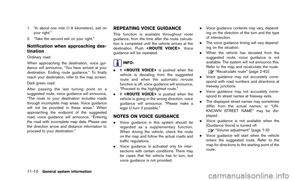
11-10General system information
1. “In about one mile (1.6 kilometers) , exit onyour right.”
2. “Take the second exit on your right.”
Notification when approaching des-
tination
Ordinary road:
When approaching the destination, voice gui-
dance will announce, “You have arrived at your
destination. Ending route guidance.” To finally
reach your destination, refer to the map screen.
Dark green road:
After passing the last turning point on a
suggested route, voice guidance will announce,
“The route to your destination includes roads
through incomplete map areas. Voice guidance
will not be provided in these areas.” When
approaching the endpoint of the suggested
road, voice guidance will announce, “Entering
the road with incomplete map data. Please use
the direction arrow and distance information to
proceed to your destination.”
REPEATING VOICE GUIDANCE
This function is available throughout route
guidance, from the time after the route calcula-
tion is completed until the vehicle arrives at the
destination. Push
guidance will be repeated.
INFO:
. If
vehicle is deviating from the suggested
route and when the automatic reroute
function is off, voice guidance will announce,
“Proceed to the highlighted route.”
. If
vehicle is going in the wrong direction, voice
guidance will announce: “Please make a
legal U-turn if possible.”
NOTES ON VOICE GUIDANCE
. Voice guidance in this system should be
regarded as a supplementary function.
When driving the vehicle, check the route
on the map and follow the actual roads and
traffic regulations.
. Voice guidance is activated only for inter-
sections with certain conditions. There may
be cases that the vehicle has to turn, but
voice guidance is not provided. .
Voice guidance contents may vary, depend-
ing on the direction of the turn and the type
of intersection.
. The voice guidance timing will vary depend-
ing on the situation.
. When the vehicle has deviated from the
suggested route, voice guidance is not
available. The system will not announce this.
Refer to the map and recalculate the route.
“Recalculate route” (page 2-62)
. Voice guidance may not accurately corre-
spond with road numbers and directions at
freeway junctions.
. Voice guidance may not accurately corre-
spond to street names at freeway exits.
. The displayed street names may sometimes
differ from the actual names, or “UN-
KNOWN STREET NAME” may be dis-
played.
. Voice guidance is not available when the
[Guidance Voice] is turned off.
“Volume adjustment” (page 7-6)
. Voice guidance will start when the vehicle
enters the suggested route. Refer to the
map for directions to the starting point of the
route.
Page 283 of 298
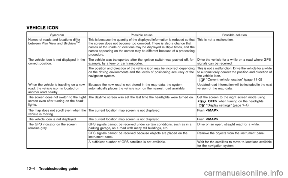
12-4Troubleshooting guide
VEHICLE ICON
SymptomPossible cause Possible solution
Names of roads and locations differ
between Plan View and Birdview
TM. This is because the quantity of the displayed information is reduced so that
the screen does not become too crowded. There is also a chance that
names of the roads or locations may be displayed multiple times, and the
names appearing on the screen may be different because of a processing
procedure. This is not a malfunction.
The vehicle icon is not displayed in the
correct position. The vehicle was transported after the ignition switch was pushed off, for
example, by a ferry or car transporter. Drive the vehicle for a while on a road where GPS
signals can be received.
The position and direction of the vehicle icon may be incorrect depending
on the driving environments and the levels of positioning accuracy of the
navigation system. This is not a malfunction. Drive the vehicle for a while
to automatically correct the position and direction of
the vehicle icon.
“Current vehicle location” (page 11-2)
When the vehicle is traveling on a new
road, the vehicle icon is located on
another road nearby. Because the new road is not stored in the map data, the system
automatically places the vehicle icon on the nearest road available.
Updated road information will be included in the next
version of the map data.
The screen does not switch to the night
screen even after turning on the head-
lights. The daytime screen was set the last time the headlights were turned on. Set the screen to the night screen mode using
<
OFF>when turning on the headlights.“Display settings” (page 7-4)
The map does not scroll even when the
vehicle is moving. The current location map screen is not displayed.
Push
Page 285 of 298
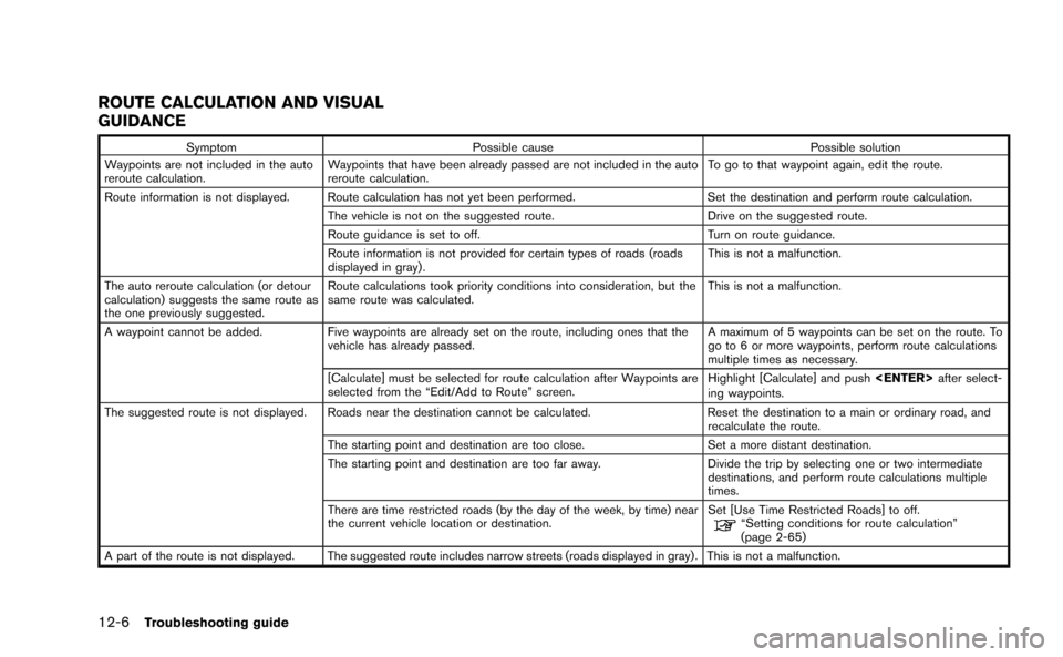
12-6Troubleshooting guide
ROUTE CALCULATION AND VISUAL
GUIDANCE
SymptomPossible cause Possible solution
Waypoints are not included in the auto
reroute calculation. Waypoints that have been already passed are not included in the auto
reroute calculation. To go to that waypoint again, edit the route.
Route information is not displayed. Route calculation has not yet been performed. Set the destination and perform route calculation.
The vehicle is not on the suggested route. Drive on the suggested route.
Route guidance is set to off. Turn on route guidance.
Route information is not provided for certain types of roads (roads
displayed in gray) . This is not a malfunction.
The auto reroute calculation (or detour
calculation) suggests the same route as
the one previously suggested. Route calculations took priority conditions into consideration, but the
same route was calculated.
This is not a malfunction.
A waypoint cannot be added. Five waypoints are already set on the route, including ones that the
vehicle has already passed. A maximum of 5 waypoints can be set on the route. To
go to 6 or more waypoints, perform route calculations
multiple times as necessary.
[Calculate] must be selected for route calculation after Waypoints are
selected from the “Edit/Add to Route” screen. Highlight [Calculate] and push
ing waypoints.
The suggested route is not displayed. Roads near the destination cannot be calculated. Reset the destination to a main or ordinary road, and
recalculate the route.
The starting point and destination are too close. Set a more distant destination.
The starting point and destination are too far away. Divide the trip by selecting one or two intermediate
destinations, and perform route calculations multiple
times.
There are time restricted roads (by the day of the week, by time) near
the current vehicle location or destination. Set [Use Time Restricted Roads] to off.
“Setting conditions for route calculation”
(page 2-65)
A part of the route is not displayed. The suggested route includes narrow streets (roads displayed in gray) . This is not a malfunction.
Page 292 of 298
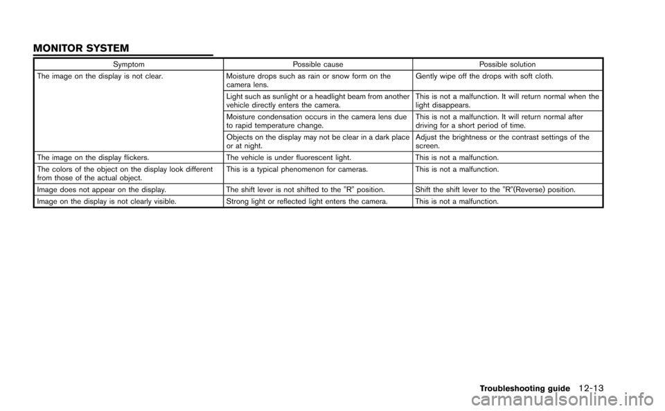
SymptomPossible cause Possible solution
The image on the display is not clear. Moisture drops such as rain or snow form on the
camera lens. Gently wipe off the drops with soft cloth.
Light such as sunlight or a headlight beam from another
vehicle directly enters the camera. This is not a malfunction. It will return normal when the
light disappears.
Moisture condensation occurs in the camera lens due
to rapid temperature change. This is not a malfunction. It will return normal after
driving for a short period of time.
Objects on the display may not be clear in a dark place
or at night. Adjust the brightness or the contrast settings of the
screen.
The image on the display flickers. The vehicle is under fluorescent light.This is not a malfunction.
The colors of the object on the display look different
from those of the actual object. This is a typical phenomenon for cameras.
This is not a malfunction.
Image does not appear on the display. The shift lever is not shifted to the "R" position. Shift the shift lever to the "R"(Reverse) position.
Image on the display is not clearly visible. Strong light or reflected light enters the camera. This is not a malfunction.
Troubleshooting guide12-13
MONITOR SYSTEM