light NISSAN JUKE 2014 F15 / 1.G Workshop Manual
[x] Cancel search | Manufacturer: NISSAN, Model Year: 2014, Model line: JUKE, Model: NISSAN JUKE 2014 F15 / 1.GPages: 402, PDF Size: 1.96 MB
Page 114 of 402
SIC3672
FOG LIGHT SWITCH (if so equipped)
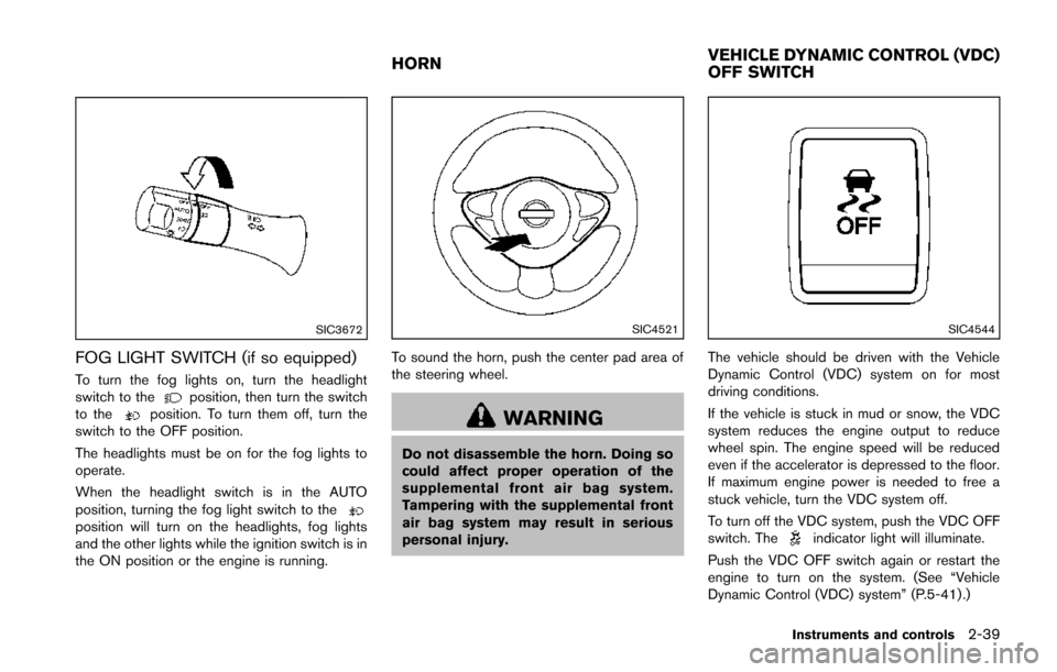
To turn the fog lights on, turn the headlight
switch to theposition, then turn the switch
to theposition. To turn them off, turn the
switch to the OFF position.
The headlights must be on for the fog lights to
operate.
When the headlight switch is in the AUTO
position, turning the fog light switch to the
position will turn on the headlights, fog lights
and the other lights while the ignition switch is in
the ON position or the engine is running.
SIC4521
To sound the horn, push the center pad area of
the steering wheel.
WARNING
Do not disassemble the horn. Doing so
could affect proper operation of the
supplemental front air bag system.
Tampering with the supplemental front
air bag system may result in serious
personal injury.
SIC4544
The vehicle should be driven with the Vehicle
Dynamic Control (VDC) system on for most
driving conditions.
If the vehicle is stuck in mud or snow, the VDC
system reduces the engine output to reduce
wheel spin. The engine speed will be reduced
even if the accelerator is depressed to the floor.
If maximum engine power is needed to free a
stuck vehicle, turn the VDC system off.
To turn off the VDC system, push the VDC OFF
switch. The
indicator light will illuminate.
Push the VDC OFF switch again or restart the
engine to turn on the system. (See “Vehicle
Dynamic Control (VDC) system” (P.5-41) .)
Instruments and controls2-39
HORN VEHICLE DYNAMIC CONTROL (VDC)
OFF SWITCH
Page 115 of 402
2-40Instruments and controls
WARNING
Do not use or allow occupants to use
the seat heater if you or the occupants
cannot monitor elevated seat tempera-
tures or have an inability to feel pain in
body parts that contact the seat. Use of
the seat heater by such people could
result in serious injury.
CAUTION
.The battery could run down if the
seat heater is operated while the
engine is not running.
. Do not use the seat heater for
extended periods or when no one
is using the seat.
. Do not put anything on the seat
which insulates heat, such as a
blanket, cushion, seat cover, etc.
Otherwise, the seat may become
overheated.
. Do not place anything hard or heavy
on the seat or pierce it with a pin or
similar object. This may result in damage to the heater.
. Any liquid spilled on the heated seat
should be removed immediately
with a dry cloth.
. When cleaning the seat, never use
gasoline, thinner, or any similar
materials.
. If any malfunctions are found or the
heated seat does not operate, turn
the switch off and have the system
checked by a NISSAN dealer.
SIC2770
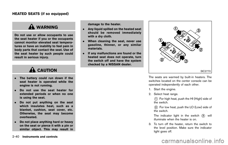
The seats are warmed by built-in heaters. The
switches located on the center console can be
operated independently of each other.
1. Start the engine.
2. Select heat range.
*1For high heat, push the HI (High) side of
the switch.
*2For low heat, push the LO (Low) side of
the switch.
The indicator light in the switch
*3will
illuminate when the heater is on.
3. To turn off the heater, return the switch to the level position. Make sure the indicator
light goes off.
HEATED SEATS (if so equipped)
Page 116 of 402
The heater is controlled by a thermostat,
automatically turning the heater on and off.
The indicator light will remain on as long as
the switch is on.
When the vehicle’s interior is warmed, or
before you leave the vehicle, be sure to turn
off the switch.The digital clock (in the audio unit) displays time
when the ignition switch is in the ACC or ON
position. The clock ON or OFF mode can be
selected. For details of the digital clock in the
NAVIGATION SYSTEM, refer to “Clock” (P.4-8) .
If the power supply is disconnected, the
clock will not indicate the correct time.
Readjust the time.
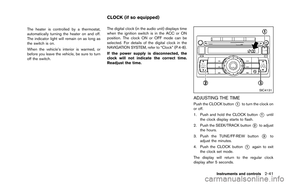
SIC4131
ADJUSTING THE TIME
Push the CLOCK button*1to turn the clock on
or off.
1. Push and hold the CLOCK button
*1until
the clock display starts to flash.
2. Push the SEEK/TRACK button
*2to adjust
the hours.
3. Push the TUNE/FF·REW button
*3to
adjust the minutes.
4. Push the CLOCK button
*1again to exit
the clock set mode.
The display will return to the regular clock
display after 5 seconds.
Instruments and controls2-41
CLOCK (if so equipped)
Page 117 of 402
2-42Instruments and controls
SIC4525
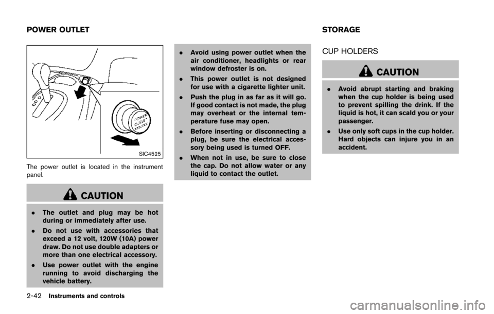
The power outlet is located in the instrument
panel.
CAUTION
.The outlet and plug may be hot
during or immediately after use.
. Do not use with accessories that
exceed a 12 volt, 120W (10A) power
draw. Do not use double adapters or
more than one electrical accessory.
. Use power outlet with the engine
running to avoid discharging the
vehicle battery. .
Avoid using power outlet when the
air conditioner, headlights or rear
window defroster is on.
. This power outlet is not designed
for use with a cigarette lighter unit.
. Push the plug in as far as it will go.
If good contact is not made, the plug
may overheat or the internal tem-
perature fuse may open.
. Before inserting or disconnecting a
plug, be sure the electrical acces-
sory being used is turned OFF.
. When not in use, be sure to close
the cap. Do not allow water or any
liquid to contact the outlet.
CUP HOLDERS
CAUTION
.Avoid abrupt starting and braking
when the cup holder is being used
to prevent spilling the drink. If the
liquid is hot, it can scald you or your
passenger.
. Use only soft cups in the cup holder.
Hard objects can injure you in an
accident.
POWER OUTLET STORAGE
Page 119 of 402
2-44Instruments and controls
SIC4526
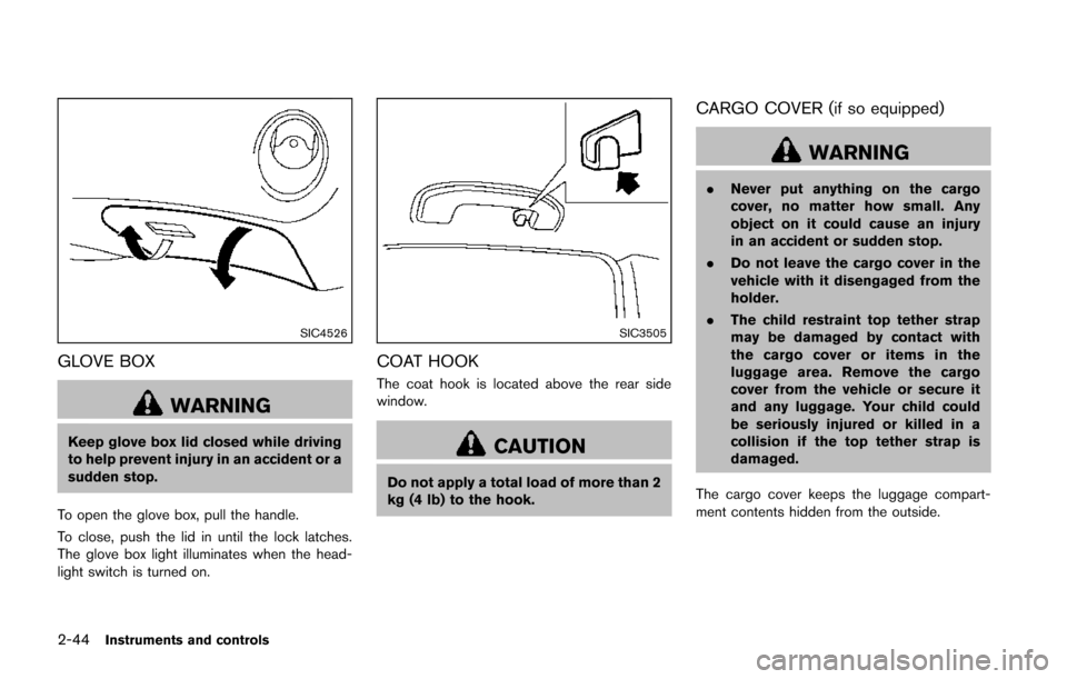
GLOVE BOX
WARNING
Keep glove box lid closed while driving
to help prevent injury in an accident or a
sudden stop.
To open the glove box, pull the handle.
To close, push the lid in until the lock latches.
The glove box light illuminates when the head-
light switch is turned on.
SIC3505
COAT HOOK
The coat hook is located above the rear side
window.
CAUTION
Do not apply a total load of more than 2
kg (4 lb) to the hook.
CARGO COVER (if so equipped)
WARNING
. Never put anything on the cargo
cover, no matter how small. Any
object on it could cause an injury
in an accident or sudden stop.
. Do not leave the cargo cover in the
vehicle with it disengaged from the
holder.
. The child restraint top tether strap
may be damaged by contact with
the cargo cover or items in the
luggage area. Remove the cargo
cover from the vehicle or secure it
and any luggage. Your child could
be seriously injured or killed in a
collision if the top tether strap is
damaged.
The cargo cover keeps the luggage compart-
ment contents hidden from the outside.
Page 122 of 402
SIC4524
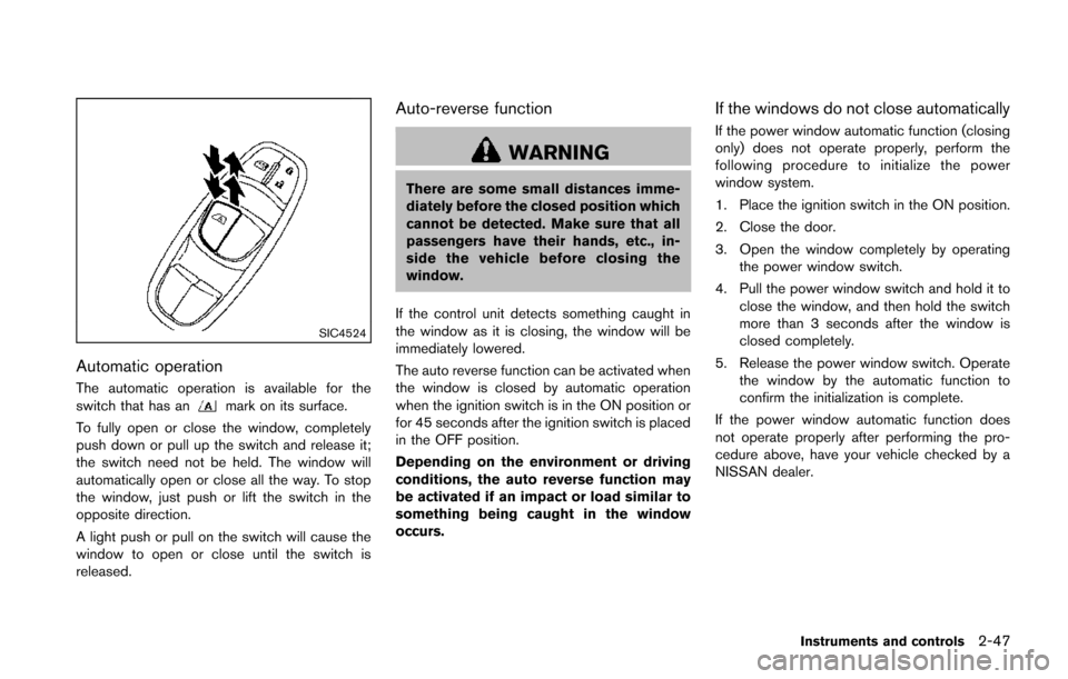
Automatic operation
The automatic operation is available for the
switch that has anmark on its surface.
To fully open or close the window, completely
push down or pull up the switch and release it;
the switch need not be held. The window will
automatically open or close all the way. To stop
the window, just push or lift the switch in the
opposite direction.
A light push or pull on the switch will cause the
window to open or close until the switch is
released.
Auto-reverse function
WARNING
There are some small distances imme-
diately before the closed position which
cannot be detected. Make sure that all
passengers have their hands, etc., in-
side the vehicle before closing the
window.
If the control unit detects something caught in
the window as it is closing, the window will be
immediately lowered.
The auto reverse function can be activated when
the window is closed by automatic operation
when the ignition switch is in the ON position or
for 45 seconds after the ignition switch is placed
in the OFF position.
Depending on the environment or driving
conditions, the auto reverse function may
be activated if an impact or load similar to
something being caught in the window
occurs.
If the windows do not close automatically
If the power window automatic function (closing
only) does not operate properly, perform the
following procedure to initialize the power
window system.
1. Place the ignition switch in the ON position.
2. Close the door.
3. Open the window completely by operating the power window switch.
4. Pull the power window switch and hold it to close the window, and then hold the switch
more than 3 seconds after the window is
closed completely.
5. Release the power window switch. Operate the window by the automatic function to
confirm the initialization is complete.
If the power window automatic function does
not operate properly after performing the pro-
cedure above, have your vehicle checked by a
NISSAN dealer.
Instruments and controls2-47
Page 124 of 402
Auto reverse function
WARNING
There are some small distances imme-
diately before the closed position which
cannot be detected. Make sure that all
passengers have their hands, etc., in-
side the vehicle before closing the
moonroof.
If the control unit detects something caught in
the moonroof when it is closing, the moonroof
will be immediately opened.
The auto reverse function can be activated when
the moonroof is closed by automatic operation
when the ignition switch is in the ON position or
for about 45 seconds after the ignition switch is
turned to the OFF position.
If the moonroof cannot be closed automatically
when the auto reverse function activates due to
a malfunction, push and hold the switch toward
*2.
Depending on the environment or driving
conditions, the auto reverse function may
be activated if an impact or load similar to
something being caught in the moonroof
occurs.
If the moonroof does not operate
If the moonroof does not operate properly,
perform the following procedure to initialize the
moonroof operation system.
1. If the moonroof is open, close it fully by repeatedly pushing the switch toward
*2.
2. Push and hold the switch toward
*2to
tilt the moonroof up.
3. Release the moonroof switch after the moonroof moves slightly up and down.
4. Push and hold the switch toward
*1to
fully tilt the moonroof down.
5. Check if the moonroof switch operates normally.
If the moonroof does not operate properly after
performing the procedure above, have your
vehicle checked by a NISSAN dealer.
CAUTION
Do not use for extended periods of time
with the engine stopped. This could
result in a discharged battery.
Instruments and controls2-49
INTERIOR LIGHTS
Page 125 of 402
2-50Instruments and controls
SIC4572
MAP LIGHTS (if so equipped)
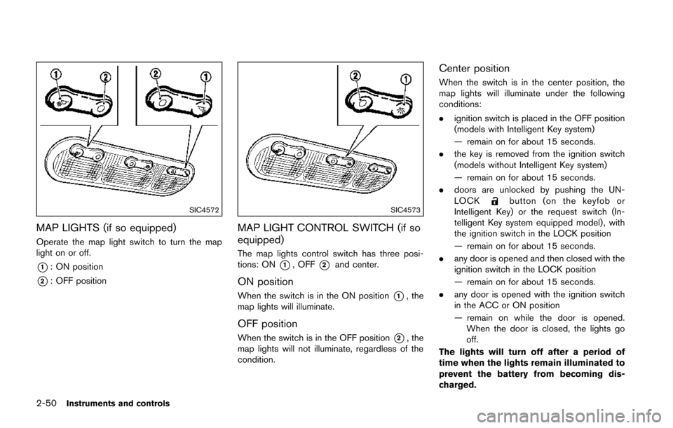
Operate the map light switch to turn the map
light on or off.
*1: ON position
*2: OFF position
SIC4573
MAP LIGHT CONTROL SWITCH (if so
equipped)
The map lights control switch has three posi-
tions: ON
*1, OFF*2and center.
ON position
When the switch is in the ON position*1, the
map lights will illuminate.
OFF position
When the switch is in the OFF position*2, the
map lights will not illuminate, regardless of the
condition.
Center position
When the switch is in the center position, the
map lights will illuminate under the following
conditions:
. ignition switch is placed in the OFF position
(models with Intelligent Key system)
— remain on for about 15 seconds.
. the key is removed from the ignition switch
(models without Intelligent Key system)
— remain on for about 15 seconds.
. doors are unlocked by pushing the UN-
LOCK
button (on the keyfob or
Intelligent Key) or the request switch (In-
telligent Key system equipped model) , with
the ignition switch in the LOCK position
— remain on for about 15 seconds.
. any door is opened and then closed with the
ignition switch in the LOCK position
— remain on for about 15 seconds.
. any door is opened with the ignition switch
in the ACC or ON position
— remain on while the door is opened.
When the door is closed, the lights go
off.
The lights will turn off after a period of
time when the lights remain illuminated to
prevent the battery from becoming dis-
charged.
Page 126 of 402
CARGO LIGHT
The cargo room lights illuminate when the lift
gate is opened. When the lift gate is closed, the
lights will turn off.
Instruments and controls2-51
Page 128 of 402

3 Pre-driving checks and adjustments
Keys ........................................................................\
...................... 3-2NISSAN Vehicle Immobilizer System keys ................... 3-2
Intelligent Keys (if so equipped) ..................................... 3-3
Doors ........................................................................\
.................... 3-4 Locking with key .................................................................. 3-5
Locking with inside lock knob .......................................... 3-5
Locking with power door lock switch ............................ 3-5
Automatic door locks ......................................................... 3-6
Child safety rear door lock ............................................... 3-6
Remote keyless entry system (if so equipped) ................. 3-7
How to use remote keyless entry system ..................... 3-8
Intelligent Key system (if so equipped) ............................ 3-10 Intelligent Key operating range ..................................... 3-12
Door locks/unlocks precaution ..................................... 3-12
Intelligent Key operation ................................................. 3-13
Battery saver system ....................................................... 3-14 Warning lights and audible reminders ...................... 3-14
Troubleshooting guide .................................................. 3-15
How to use remote keyless entry function .............. 3-16
Hood ........................................................................\
................. 3-19
Lift gate ........................................................................\
............ 3-20
Front side and rear unique parts (NISMO models) ..... 3-20
Fuel-filler door ........................................................................\
3-21 Opening the fuel-filler door ......................................... 3-21
Fuel-filler cap .................................................................. 3-21
Tilt steering column .............................................................. 3-23
Tilt operation ................................................................... 3-24
Sun visors ........................................................................\
........ 3-24
Mirrors ........................................................................\
............. 3-25
Inside mirror ..................................................................... 3-25
Outside mirrors ............................................................... 3-25
Vanity mirror ..................................................................... 3-27