brake NISSAN KICKS 2020 Owner´s Manual
[x] Cancel search | Manufacturer: NISSAN, Model Year: 2020, Model line: KICKS, Model: NISSAN KICKS 2020Pages: 500, PDF Size: 3.43 MB
Page 375 of 500
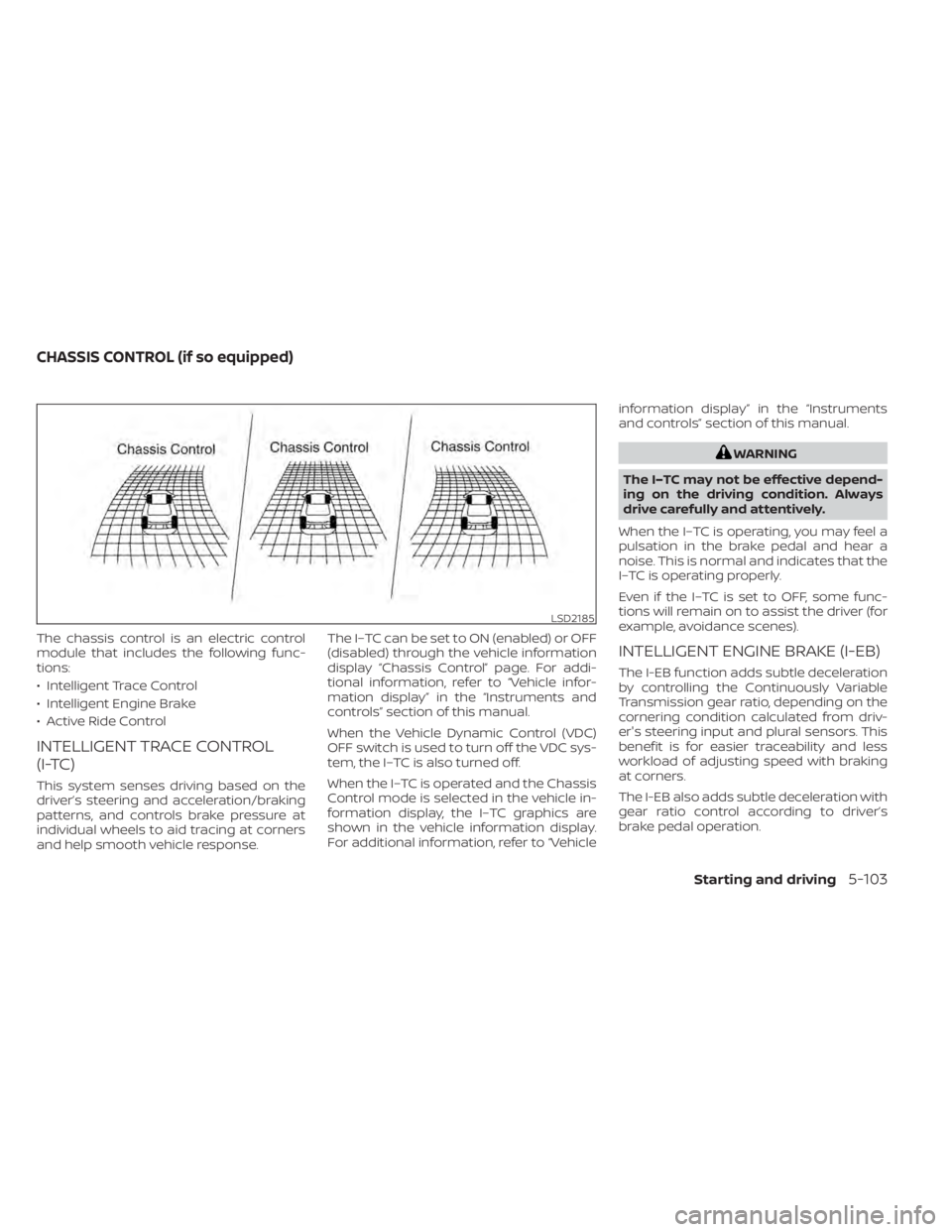
The chassis control is an electric control
module that includes the following func-
tions:
• Intelligent Trace Control
• Intelligent Engine Brake
• Active Ride Control
INTELLIGENT TRACE CONTROL
(I-TC)
This system senses driving based on the
driver’s steering and acceleration/braking
patterns, and controls brake pressure at
individual wheels to aid tracing at corners
and help smooth vehicle response.The I–TC can be set to ON (enabled) or OFF
(disabled) through the vehicle information
display “Chassis Control” page. For addi-
tional information, refer to “Vehicle infor-
mation display” in the “Instruments and
controls” section of this manual.
When the Vehicle Dynamic Control (VDC)
OFF switch is used to turn off the VDC sys-
tem, the I–TC is also turned off.
When the I–TC is operated and the Chassis
Control mode is selected in the vehicle in-
formation display, the I–TC graphics are
shown in the vehicle information display.
For additional information, refer to “Vehicleinformation display” in the “Instruments
and controls” section of this manual.
WARNING
The I–TC may not be effective depend-
ing on the driving condition. Always
drive carefully and attentively.
When the I–TC is operating, you may feel a
pulsation in the brake pedal and hear a
noise. This is normal and indicates that the
I–TC is operating properly.
Even if the I–TC is set to OFF, some func-
tions will remain on to assist the driver (for
example, avoidance scenes).
INTELLIGENT ENGINE BRAKE (I-EB)
The I-EB function adds subtle deceleration
by controlling the Continuously Variable
Transmission gear ratio, depending on the
cornering condition calculated from driv-
er's steering input and plural sensors. This
benefit is for easier traceability and less
workload of adjusting speed with braking
at corners.
The I-EB also adds subtle deceleration with
gear ratio control according to driver’s
brake pedal operation.
LSD2185
CHASSIS CONTROL (if so equipped)
Starting and driving5-103
Page 376 of 500
The I-EB can be set to ON (enabled) or OFF
(disabled) through the vehicle information
display “Chassis Control” page. For addi-
tional information, refer to “Vehicle infor-
mation display” in the “Instruments and
controls” section of this manual.
When the I-EB is operated at corners and
the Chassis Control mode is selected in the
vehicle information display, the I-EB graph-
ics are shown in the vehicle information
display. For additional information, refer to
“Vehicle information display” in the “Instru-
ments and controls” section of this manual.
WARNING
The I-EB may not be effective depend-
ing on driving conditions. Always drive
carefully and attentively.
When the I-EB is operating, the needle of
the tachometer will rise up and you may
hear an engine noise. This is normal and
indicates that the I-EB is operating prop-
erly.
ACTIVE RIDE CONTROL (ARC)
This system senses upper body motion
based on wheel speed information and
controls four wheel brake pressure to en-
hance ride comfort in effort to restrain un-
comfortable upper body movement. This
system comes into effect above 25 mph
(40 km/h). When the VDC OFF switch is
used to turn off the VDC system, the ARC is
also turned off.
When the brake control of the ARC is oper-
ated and the Chassis Control mode is se-
lected in the vehicle information display,
the ARC graphics are shown in the vehicle
information display. For additional infor-
mation, refer to “Vehicle information dis-
play” in the “Instruments and controls” sec-
tion of this manual.
When the ARC is operating, you may hear
noise and sense slight deceleration. This is
normal and indicates that the ARC is oper-
ating properly.
WARNING
• Never rely solely on the hill start as-
sist system to prevent the vehicle
from moving backward on a hill. Al-
ways drive carefully and attentively.
Depress the brake pedal when the
vehicle is stopped on a steep hill. Be
especially careful when stopped on a
hill on frozen or muddy roads. Failure
to prevent the vehicle from rolling
backwards may result in a loss of
control of the vehicle and possible
serious injury or death.
• The hill start assist system is not de-
signed to hold the vehicle at a stand-
still on a hill. Depress the brake pedal
when the vehicle is stopped on a
steep hill. Failure to do so may cause
the vehicle to roll backwards and
may result in a collision or serious
personal injury.
• The hill start assist may not prevent
the vehicle from rolling backwards
on a hill under all load or road condi-
tions. Always be prepared to depress
the brake pedal to prevent the ve-
hicle from rolling backwards. Failure
to do so may result in a collision or
serious personal injury.
HILL START ASSIST SYSTEM
5-104Starting and driving
Page 377 of 500
The hill start assist system automatically
keeps the brakes applied to help prevent
the vehicle from rolling backwards in the
time it takes the driver to release the brake
pedal and apply the accelerator when the
vehicle is stopped on a hill.
The hill start assist system will operate au-
tomatically under the following conditions:
• The transmission is shif ted to a forwardor reverse gear.
• The vehicle is stopped completely on a hill by applying the brake.
The maximum holding time is 2 seconds.
Af ter 2 seconds the vehicle will begin to roll
back and the hill start assist system will
stop operating completely.
The hill start assist system will not operate
when the transmission is shif ted to the N
(Neutral) or P (Park) position or on a flat and
level road.
When the Vehicle Dynamic Control (VDC)
indicator light illuminates in the meter, the
hill start assist system will not operate. For
additional information, refer to “Vehicle Dy-
namic Control (VDC) indicator light” in the
“Instruments and controls” section of this
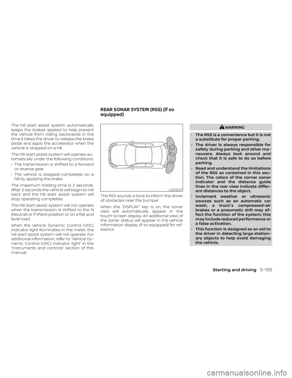
manual. The RSS sounds a tone to inform the driver
of obstacles near the bumper.
When the “DISPLAY” key is on, the sonar
view will automatically appear in the
touch-screen display. An additional view of
the sonar status will appear in the vehicle
information display (if so equipped) for ref-
erence.WARNING
• The RSS is a convenience but it is not
a substitute for proper parking.
• The driver is always responsible for
safety during parking and other ma-
neuvers. Always look around and
check that it is safe to do so before
parking.
• Read and understand the limitations
of the RSS as contained in this sec-
tion. The colors of the corner sonar
indicator and the distance guide
lines in the rear view indicate differ-
ent distances to the object.
• Inclement weather or ultrasonic
sources such as an automatic car
wash, a truck's compressed-air
brakes or a pneumatic drill may af-
fect the function of the system; this
may include reduced performance or
a false activation.
• This function is designed as an aid to
the driver in detecting large station-
ary objects to help avoid damaging
the vehicle.
LSD3247
REAR SONAR SYSTEM (RSS) (if so
equipped)
Starting and driving5-105
Page 382 of 500
•Inclement weather or ultrasonic
sources such as an automatic car
wash, a truck’s compressed-air
brakes or a pneumatic drill may af-
fect the function of the system; this
may include reduced performance or
a false activation.
• The system is not designed to pre-
vent contact with small or moving
objects. Always move slowly. The
system will not detect small objects
below the bumper or on the ground.
• The system may not detect the fol-
lowing objects: fluff y objects such as
snow, cloth, cotton, glass-wool, etc.;
thin objects such as rope, wire and
chain, etc.; or wedge-shaped objects.
• The system may not detect objects
at speeds above 3 mph (5 km/h) and
may not detect certain angular or
moving objects.
SYSTEM TEMPORARILY
UNAVAILABLE
When sonar blockage is detected, the sys-
tem will be deactivated automatically.
The system is not available until the condi-
tions no longer exist. The sonar sensors may be blocked by tem-
porary ambient conditions such as splash-
ing water, mist or fog. The blocked condi-
tion may also be caused by objects such as
ice, frost or dirt obstructing the sonar sen-
sors.
Action to take:
When the above conditions no longer exist,
the system will resume automatically.
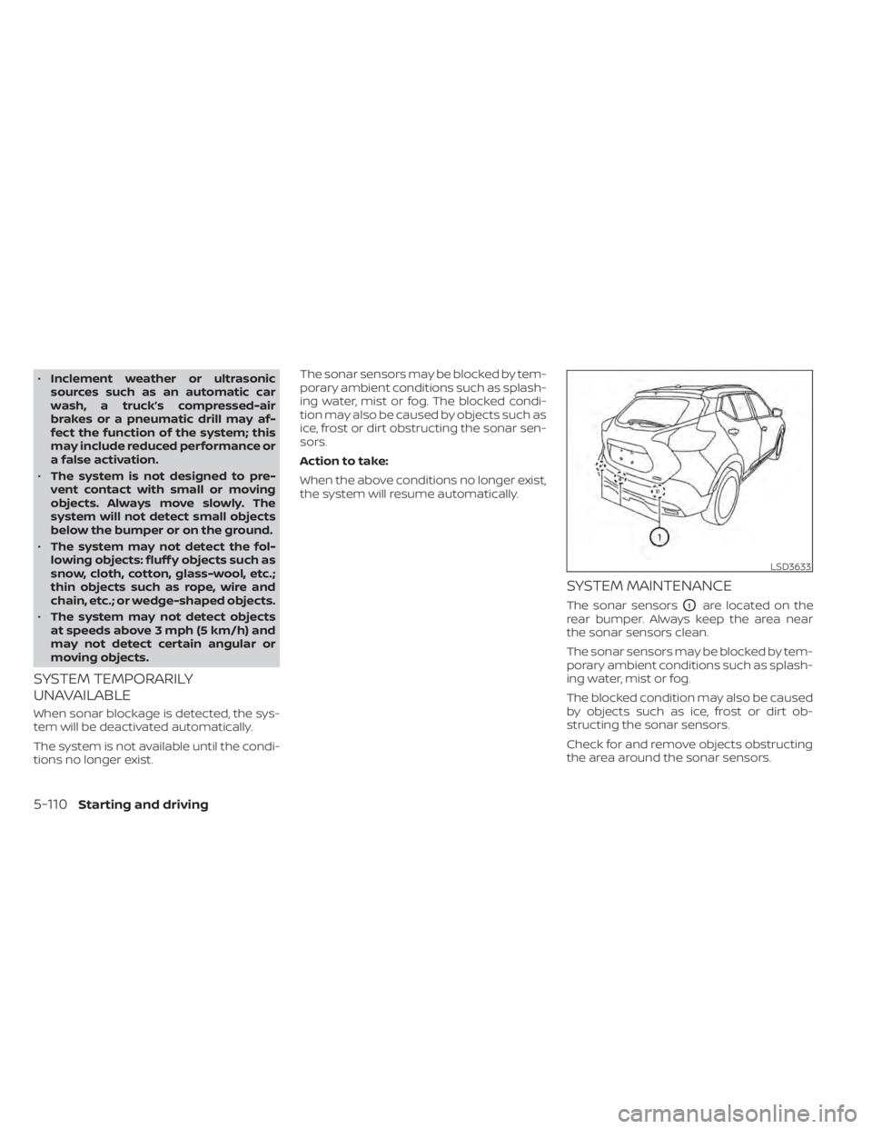
SYSTEM MAINTENANCE
The sonar sensorsO1are located on the
rear bumper. Always keep the area near
the sonar sensors clean.
The sonar sensors may be blocked by tem-
porary ambient conditions such as splash-
ing water, mist or fog.
The blocked condition may also be caused
by objects such as ice, frost or dirt ob-
structing the sonar sensors.
Check for and remove objects obstructing
the area around the sonar sensors.
LSD3633
5-110Starting and driving
Page 384 of 500
SPECIAL WINTER EQUIPMENT
It is recommended that the following items
be carried in the vehicle during winter:
• A scraper and stiff-bristled brush to re-move ice and snow from the windows
and wiper blades.
• A sturdy, flat board to be placed under the jack to give it firm support.
• A shovel to dig the vehicle out of snow- drif ts.
• Extra washer fluid to refill the windshield- washer fluid reservoir.
DRIVING ON SNOW OR ICE
WARNING
• Wet ice (32°F, 0°C and freezing rain),
very cold snow or ice can be slick and
very hard to drive on. The vehicle will
have much less traction or “grip” un-
der these conditions. Try to avoid
driving on wet ice until the road is
salted or sanded.
• Whatever the condition, drive with
caution. Accelerate and slow down
with care. If accelerating or down-
shif ting too fast, the drive wheels will
lose even more traction. •
Allow more stopping distance under
these conditions. Braking should be
started sooner than on dry
pavement.
• Allow greater following distances on
slippery roads.
• Watch for slippery spots (glare ice).
These may appear on an otherwise
clear road in shaded areas. If a patch
of ice is seen ahead, brake before
reaching it. Try not to brake while on
the ice, and avoid any sudden steer-
ing maneuvers.
• Do not use the cruise control on slip-
pery roads.
• Snow can trap dangerous exhaust
gases under your vehicle. Keep snow
clear of the exhaust pipe and from
around your vehicle.
PARKING BRAKE
When parking in an area where the outside
temperature is below 32°F (0°C), do not ap-
ply the parking brake to prevent it from
freezing. For safe parking:
• Place the shif t lever in the P (Park) posi- tion.
• Securely block the wheels.
ENGINE BLOCK HEATER (if so
equipped)
Engine block heaters are used to assist
with cold temperature starting.
The engine block heater should be used
when the outside temperature is 20°F (-7°C)
or lower.
WARNING
• Do not use your engine block heater
with an ungrounded electrical sys-
tem or a 2-pronged adapter. You can
be seriously injured by an electrical
shock if you use an ungrounded
connection.
• Disconnect and properly store the
engine block heater cord before
starting the engine. Damage to the
cord could result in an electrical
shock and can cause serious injury.
• Use a heavy-duty 3-wire, 3-pronged
extension cord rated for at least 10 A.
Plug the extension cord into a
Ground Fault Interrupt (GFI) pro-
tected, grounded 110-VAC outlet.
Failure to use the proper extension
cord or a grounded outlet can result
in a fire or electrical shock and cause
serious personal injury.
5-112Starting and driving
Page 390 of 500
CHANGING A FLAT TIRE
If you have a flat tire, follow the instructions
below:
Stopping the vehicle
1. Safely move the vehicle off the road andaway from traffic.
2. Turn on the hazard warning flashers.
3. Park on a level surface and apply the parking brake. Move the shif t lever to P
(Park).
4. Turn off the engine.
5. Raise the hood to warn other traffic and to signal professional road assistance
personnel that you need assistance.
6. Have all passengers get out of the ve- hicle and stand in a safe place, away
from traffic and clear of the vehicle.
WARNING
• Make sure the parking brake is se-
curely applied and the Continuously
Variable Transmission (CVT) is
shif ted into P (Park).
• Never change tires when the vehicle
is on a slope, ice or slippery areas.
This is hazardous.
• Never change tires if oncoming traf-
fic is close to your vehicle. Wait for
professional road assistance.
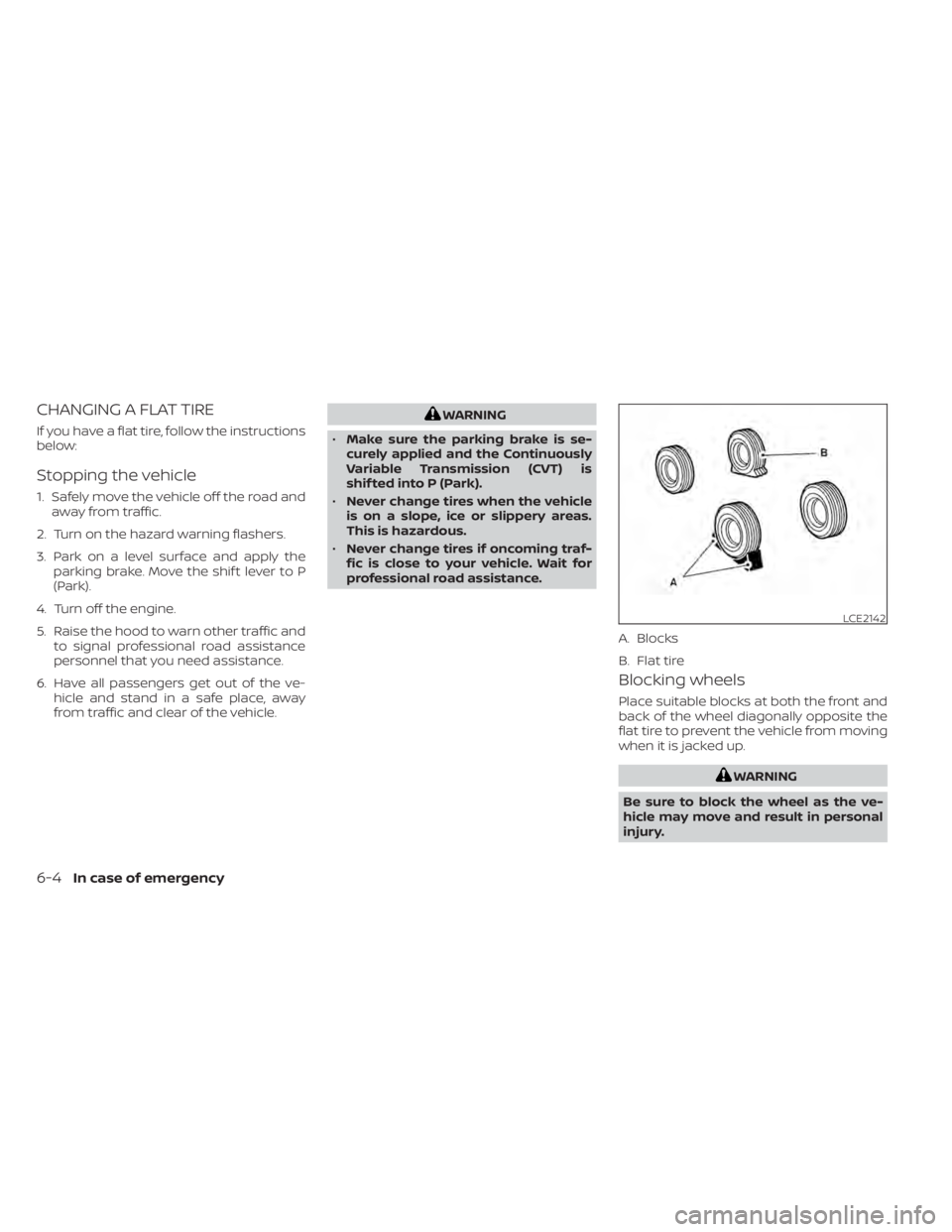
Blocking wheels
Place suitable blocks at both the front and
back of the wheel diagonally opposite the
flat tire to prevent the vehicle from moving
when it is jacked up.
WARNING
Be sure to block the wheel as the ve-
hicle may move and result in personal
injury.
LCE2142
A. Blocks
B. Flat tire
6-4In case of emergency
Page 396 of 500
•Whenever working on or near a bat-
tery, always wear suitable eye pro-
tectors (for example, goggles or in-
dustrial safety spectacles) and
remove rings, metal bands, or any
other jewelry. Do not lean over the
battery when jump starting.
• Do not attempt to jump start a frozen
battery. It could explode and cause
serious injury.
• The automatic engine cooling fan (if
so equipped) may come on at any
time without warning, even if the ig-
nition switch is in the OFF position
and the engine is not running. To
avoid injury, keep hands and other
objects away from it.
WARNING
Always follow the instructions below.
Failure to do so could result in damage
to the charging system and cause per-
sonal injury.
1. If the booster battery is in another ve- hicle, position the 2 vehicles to bring their
batteries near each other.
Do not allow the two vehicles to touch.
2. Apply the parking brake. Move the shif t lever to P (Park). Switch off all unneces-
sary electrical systems (lights, heater, air
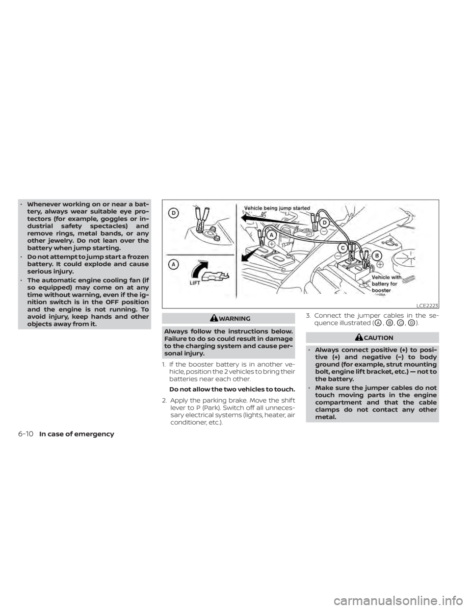
conditioner, etc.). 3. Connect the jumper cables in the se-
quence illustrated (OA,OB,OC,OD).
CAUTION
• Always connect positive (+) to posi-
tive (+) and negative (−) to body
ground (for example, strut mounting
bolt, engine lif t bracket, etc.) — not to
the battery.
• Make sure the jumper cables do not
touch moving parts in the engine
compartment and that the cable
clamps do not contact any other
metal.
LCE2223
6-10In case of emergency
Page 397 of 500
4. Start the engine of the booster vehicleand let it run for a few minutes.
5. Keep the engine speed of the booster vehicle at about 2,000 rpm and start the
engine of the vehicle being jump
started.
CAUTION
Do not keep the starter motor engaged
for more than 10 seconds. If the engine
does not start right away, place the ig-
nition switch in the OFF position and
wait 3 to 4 seconds before trying again.
6. Af ter starting the engine, carefully dis- connect the negative cable and then the
positive cable.
CAUTION
• Do not push start this vehicle. The
three-way catalyst may be
damaged.
• Continuously Variable Transmission
(CVT) models cannot be push-
started or tow-started. Attempting
to do so may cause transmission
damage. If your vehicle is overheating (indicated by a
(red) high temperature warning light(if
so equipped)), or if you feel a lack of engine
power, detect abnormal noise, etc., take the
following steps.
WARNING
• Do not continue to drive if your ve-
hicle overheats. Doing so could cause
engine damage or a vehicle fire.
• To avoid the danger of being scalded,
never remove the coolant reservoir
cap while the engine is still hot. When
the coolant reservoir cap is removed,
pressurized hot water will spurt out,
possibly causing serious injury.
• Do not open the hood if steam is
coming out.
1. Move the vehicle safely off the road, ap- ply the parking brake and move the shif t
lever to P (Park).
Do not stop the engine.
2. Turn off the air conditioner. Open all the windows, move the heater or air condi-
tioner temperature control to maximum
hot and fan control to high speed.
PUSH STARTING IF YOUR VEHICLE OVERHEATS
In case of emergency6-11
Page 406 of 500
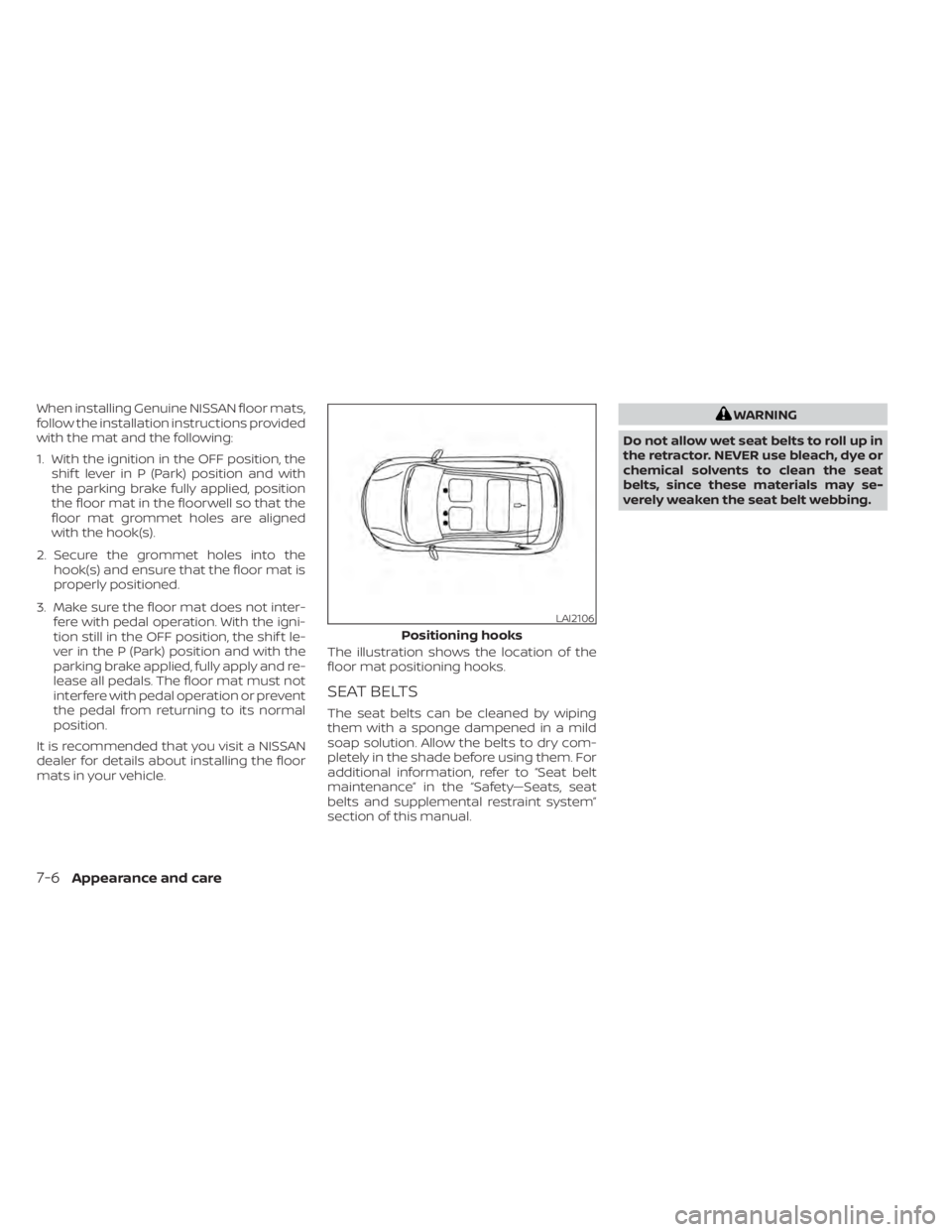
When installing Genuine NISSAN floor mats,
follow the installation instructions provided
with the mat and the following:
1. With the ignition in the OFF position, theshif t lever in P (Park) position and with
the parking brake fully applied, position
the floor mat in the floorwell so that the
floor mat grommet holes are aligned
with the hook(s).
2. Secure the grommet holes into the hook(s) and ensure that the floor mat is
properly positioned.
3. Make sure the floor mat does not inter- fere with pedal operation. With the igni-
tion still in the OFF position, the shif t le-
ver in the P (Park) position and with the
parking brake applied, fully apply and re-
lease all pedals. The floor mat must not
interfere with pedal operation or prevent
the pedal from returning to its normal
position.
It is recommended that you visit a NISSAN
dealer for details about installing the floor
mats in your vehicle. The illustration shows the location of the
floor mat positioning hooks.
SEAT BELTS
The seat belts can be cleaned by wiping
them with a sponge dampened in a mild
soap solution. Allow the belts to dry com-
pletely in the shade before using them. For
additional information, refer to “Seat belt
maintenance” in the “Safety—Seats, seat
belts and supplemental restraint system”
section of this manual.
WARNING
Do not allow wet seat belts to roll up in
the retractor. NEVER use bleach, dye or
chemical solvents to clean the seat
belts, since these materials may se-
verely weaken the seat belt webbing.
LAI2106
Positioning hooks
7-6Appearance and care
Page 407 of 500
MOST COMMON FACTORS
CONTRIBUTING TO VEHICLE
CORROSION
Most vehicle corrosion is caused by:
• The accumulation of moisture-retainingdirt and debris in body panel sections,
cavities, and other areas.
• Damage to paint and other protective coatings caused by gravel and stone
chips or minor traffic collisions.
ENVIRONMENTAL FACTORS
INFLUENCE THE RATE OF
CORROSION
Moisture
Accumulation of sand, dirt and water on
the vehicle body underside can accelerate
corrosion. Wet floor coverings will not dry
completely inside the vehicle and should
be removed for drying to avoid floor panel
corrosion.
Relative humidity
Corrosion will be accelerated in areas of
high relative humidity, especially those ar-
eas where the temperatures stay above
freezing and where atmospheric pollution
exists and road salt is used.
Temperature
High temperatures accelerate the rate of
corrosion to those parts which are not well
ventilated.
Air pollution
Industrial pollution, the presence of salt in
the air in coastal areas, or heavy road salt
use accelerates the corrosion process.
Road salt also accelerates the disintegra-
tion of paint surfaces.
PROTECT YOUR VEHICLE FROM
CORROSION
• Wash and wax your vehicle of ten to keepthe vehicle clean.
• Always check for minor damage to the paint and repair it as soon as possible.
• Keep drain holes at the bottom of the doors open to avoid water accumulation.
• Check the underbody for accumulation of sand, dirt or salt. If present, wash with
water as soon as possible.
CAUTION
• NEVER remove dirt, sand or other de-
bris from the passenger compart-
ment by washing it out with a hose.
Remove dirt with a vacuum cleaner
or broom.
• Never allow water or other liquids to
come in contact with electronic com-
ponents inside the vehicle as this
may damage them.
Chemicals used for road surface de-icing
are extremely corrosive. They accelerate
corrosion and deterioration of underbody
components such as the exhaust system,
fuel and brake lines, brake cables, floor pan
and fenders.
In winter, the underbody must be
cleaned periodically.
For additional protection against rust and
corrosion, which may be required in some
areas, it is recommended that you visit a
NISSAN dealer.
CORROSION PROTECTION
Appearance and care7-7