air condition NISSAN KICKS 2021 User Guide
[x] Cancel search | Manufacturer: NISSAN, Model Year: 2021, Model line: KICKS, Model: NISSAN KICKS 2021Pages: 500, PDF Size: 3.24 MB
Page 82 of 500
SUPPLEMENTAL AIR BAG WARNING
LIGHT
The supplemental air bag warning light,
displayingin the instrument panel,
monitors the circuits for the Air bag Control
Unit (ACU), satellite sensors, crash zone
sensor, occupant classification sensor, the
supplemental front-impact air bag, front
seat-mounted side-impact supplemental
air bag, roof-mounted curtain side-impact
supplemental air bag and seat belt preten-
sioner systems. The monitored circuits in-
clude air bag systems, pretensioner(s) and
all related wiring. When the ignition switch is placed in the ON
position, the supplemental air bag warning
light illuminates for about 7 seconds and
then turns off. This means the system is
operational.
If any of the following conditions occur, the
front air bag, side air bag, curtain air bag,
knee air bag and pretensioner systems
need servicing:
• The supplemental air bag warning light
remains on af ter approximately 7 sec-
onds.
• The supplemental air bag warning light flashes intermittently.
• The supplemental air bag warning light does not come on at all.
Under these conditions, the front air bag,
side air bag, curtain air bag, knee air bag or
pretensioner systems may not operate
properly. They must be checked and re-
paired. It is recommended that you visit a
NISSAN dealer for this service.
LRS0100
1-62Safety-Seats, seat belts and supplemental restraint system
Page 102 of 500
This light illuminates when the RAB system
is turned off in the vehicle information dis-
play or set to off using the Drive Systems
OFF switch.
If the light illuminates when the RAB sys-
tem is on, it may indicate that the system is
unavailable. For additional information, re-
fer to “Rear Automatic Braking (RAB)” in the
“Starting and driving” section of this
manual.
Seat belt warning light and
chime
The light and chime remind you to fasten
your seat belts. The light illuminates when-
ever the ignition switch is placed in the ON
or START position and remains illuminated
until the driver's seat belt is fastened. At the
same time, the chime sounds for about 6
seconds unless the driver's seat belt is se-
curely fastened.
The seat belt warning light may also illumi-
nate if the front passenger's seat belt is not
fastened when the front passenger's seat
is occupied. For 7 seconds af ter the ignition
switch is placed in the ON position, the sys-
tem does not activate the warning light for
the front passenger. For additional information, refer to “Seat
belts” in the “Safety—Seats, seat belts and
supplemental restraint system” section of
this manual.
Shif t P (Park) warning light (if
so equipped)
This light blinks red and the key reminder
chime sounds if the shif t lever is in any
position other than P (Park) and the ignition
switch is in the OFF position. Return the
shif t lever to P (Park) with the ignition
switch in the OFF position and the light will
turn off. Place the ignition switch in the
LOCK position and the chime will turn off.
For additional information, refer to “NISSAN
Intelligent Key®” in the “Pre-driving checks
and adjustments” section of this manual.
Supplemental air bag
warning light
When the ignition switch is placed in the ON
or START position, the supplemental air
bag warning light illuminates for about 7
seconds and then turns off. This means the
system is operational. If any of the following conditions occur, the
front air bag, side air bag, curtain air bag,
and pretensioner seat belt systems need
servicing:
• The supplemental air bag warning light
remains on af ter approximately 7 sec-
onds.
• The supplemental air bag warning light flashes intermittently.
• The supplemental air bag warning light does not come on at all.
It is recommended that you visit a NISSAN
dealer for these services.
Unless checked and repaired, the supple-
mental restraint system (air bag system)
and/or the pretensioner(s) may not func-
tion properly. For additional information, re-
fer to “Supplemental Restraint System
(SRS)” in the “Safety—Seats, seat belts and
supplemental restraint system” section of
this manual.
2-18Instruments and controls
Page 120 of 500
WARNING
The tire replacement indicator is not a
substitute for regular tire checks, in-
cluding tire pressure checks. For addi-
tional information, refer to “Changing
wheels and tires” in the “Do-it-yourself ”
section of this manual. Many factors in-
cluding tire inflation, alignment, driving
habits and road conditions affect tire
wear and when tires should be re-
placed. Setting the tire replacement in-
dicator for a certain driving distance
does not mean your tires will last that
long. Use the tire replacement indicator
as a guide only and always perform
regular tire checks. Failure to perform
regular tire checks, including tire pres-
sure checks could result in tire failure.
Serious vehicle damage could occur
and may lead to a collision, which could
result in serious personal injury or
death.
Other
This indicator appears when the customer
set distance is reached for checking or re-
placing maintenance items other than the
engine oil, oil filter and tires. Other mainte-
nance items can include such things as air filter or tire rotation. The distance for
checking or replacing the items can be set
or reset.
Front Radar Obstruction (if so
equipped)
This warning appears when there is a radar
obstruction detected. For additional infor-
mation, refer to “Automatic Emergency
Braking (AEB)” and “Automatic Emergency
Braking (AEB) with Pedestrian Detection” in
the “Starting and driving” section of this
manual.
Side Radar Obstruction (if so
equipped)
This message appears when the Blind
Spot Warning (BSW) or Rear Cross Traffic
Alert (RCTA) systems become unavailable
because a radar blockage is detected. For
additional information, refer to “Blind Spot
Warning (BSW)” or “Rear Cross Traffic Alert
(RCTA)” in the “Starting and driving” section
of this manual.
Drive Sport mode indicator (if so
equipped)
A small “S” appears to the right of the Trans-
mission Shif t Position indicator in the ve-
hicle information display when the Drive
Sport mode is engaged.Activate the Drive Sport mode by pressing
the switch on the shif t lever while the shif t
lever is in the D (Drive) position.
For additional information, refer to “Driving
the vehicle” in the “Starting and driving” sec-
tion of this manual.
Rear Door Alert is activated (if so
equipped)
When the system is enabled, this message
appears when the Rear Door Alert system
is active and can remind the driver to check
the back seat.
• Using the steering wheel switch, a driver
can select “Dismiss Message” to clear the
display for a period of time. If no selection
is made, this message automatically
turns off af ter a period of time.
• Using the steering wheel switch, a driver can select “Disable Alert” to disable the
horn alert for the remainder of the cur-
rent trip.
2-36Instruments and controls
Page 141 of 500
WARNING
• If the driver selects “Disable Alert”, no
audible alert will be provided regard-
less of rear door open/close status.
• There may be times when there is an
object or passenger in the rear
seat(s) but the audible alert does not
sound. For example, if rear seat pas-
sengers enter or exit the vehicle dur-
ing a trip.
• The system does not directly detect
objects or passengers in the rear
seat(s). Instead, it can detect when a
rear door is opened and closed, indi-
cating that there may be something
in the rear seat(s).
NOTE:
There may be times when the horn
sounds but there are no objects or pas-
sengers in the rear seat(s).
For additional information, refer to “Rear
Door Alert is activated” in this section.
12V OUTLETS
The power outlet is for powering electrical
accessories such as cellular telephones. It
is rated at 12 volt, 120W (10A) maximum.
The front console power outlet is powered
only when the ignition switch is in the ON
position, or while the accessory power is
active.
NOTE:
• When the ignition is in the OFF position, the front console power outlet stops
delivering power one minute af ter the
door is opened and stays open. • If the door remains closed af ter the ig-
nition is placed in the OFF position, the
front console power outlet continues
to deliver power until the accessory
power timer has elapsed.
CAUTION
• The outlet and plug may be hot dur-
ing or immediately af ter use.
• Only certain power outlets are de-
signed for use with a cigarette lighter
unit. Do not use any other power out-
let for an accessory lighter. It is rec-
ommended that you visit a NISSAN
dealer for additional information.
• Do not use with accessories that ex-
ceed a 12 volt, 120W (10A) power draw.
• Do not use double adapters or more
than one electrical accessory.
• Use power outlets with the engine
running to avoid discharging the ve-
hicle battery.
• Avoid using power outlets when the
air conditioner, headlights or rear
window defroster is on.
• Before inserting or disconnecting a
plug, be sure the electrical accessory
being used is turned off.
Instruments and controls2-57
Page 165 of 500
WARNING
• Radio waves could adversely affect
electric medical equipment. Those
who use a pacemaker should contact
the electric medical equipment
manufacturer for the possible influ-
ences before use.
• The Intelligent Key transmits radio
waves when the buttons are pressed.
The FAA advises the radio waves may
affect aircraf t navigation and com-
munication systems. Do not operate
the Intelligent Key while on an air-
plane. Make sure the buttons are not
operated unintentionally when the
unit is stored for a flight.
• Never leave the Intelligent Key in the
vehicle when you leave the vehicle.
The Intelligent Key system can operate all
the door and lif tgate locks using the re-
mote control function or pushing the re-
quest switch (if so equipped) on the vehicle
without taking the key out from a pocket or
purse. The operating environment and/or
conditions may affect the Intelligent Key
system operation.
Be sure to read the following before using
the Intelligent Key system.
Page 188 of 500
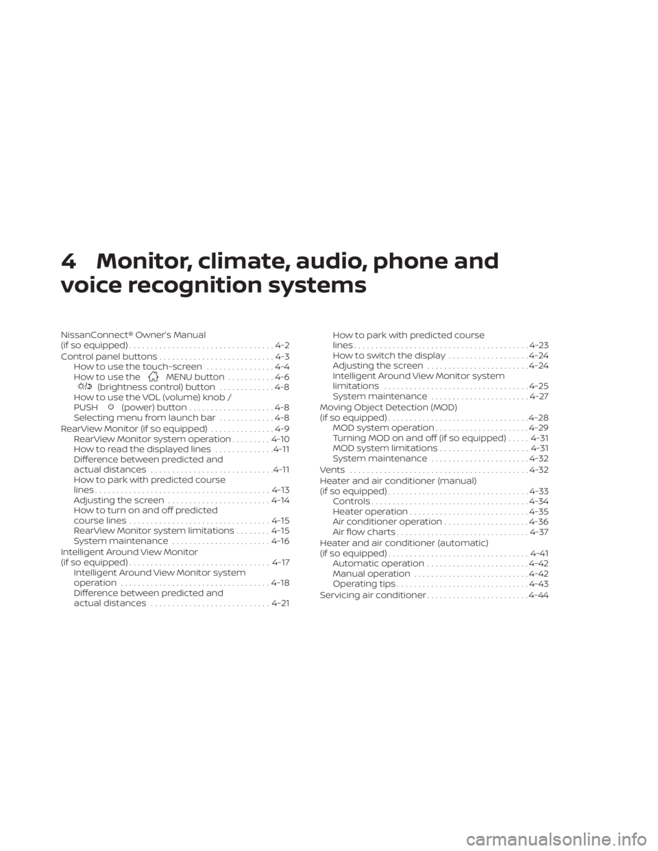
4 Monitor, climate, audio, phone and
voice recognition systems
NissanConnect® Owner’s Manual
(if so equipped)..................................4-2
Control panel buttons ...........................4-3
How to use the touch-screen ................4-4
How to use the
MENU button ...........4-6(brightness control) button .............4-8
How to use the VOL (volume) knob /
PUSH
(power)button....................4-8
Selecting menu from launch bar .............4-8
RearView Monitor (if so equipped) ...............4-9
RearView Monitor system operation .........4-10
How to read the displayed lines ..............4-11
Difference between predicted and
actual distances ............................. 4-11
How to park with predicted course
lines ......................................... 4-13
Adjusting the screen ........................ 4-14
How to turn on and off predicted
course lines ................................. 4-15
RearView Monitor system limitations ........4-15
System maintenance ....................... 4-16
Intelligent Around View Monitor
(if so equipped) ................................. 4-17
Intelligent Around View Monitor system
operation ................................... 4-18
Difference between predicted and
actual distances ............................ 4-21How to park with predicted course
lines
......................................... 4-23
How to switch the display ...................4-24
Adjusting the screen ........................ 4-24
Intelligent Around View Monitor system
limitations .................................. 4-25
System maintenance .......................4-27
Moving Object Detection (MOD)
(if so equipped) ................................. 4-28
MOD system operation ......................4-29
Turning MOD on and off (if so equipped) .....4-31
MOD system limitations .....................4-31
System maintenance .......................4-32
Vents .......................................... 4-32
Heater and air conditioner (manual)
(if so equipped) ................................. 4-33
Controls ..................................... 4-34
Heater operation ............................ 4-35
Air conditioner operation ....................4-36
Air flow charts ............................... 4-37
Heater and air conditioner (automatic)
(if so equipped) ................................. 4-41
Automatic operation ........................ 4-42
Manual operation ........................... 4-42
Operating tips ............................... 4-43
Ser
vicing air conditioner ........................ 4-44
Page 222 of 500
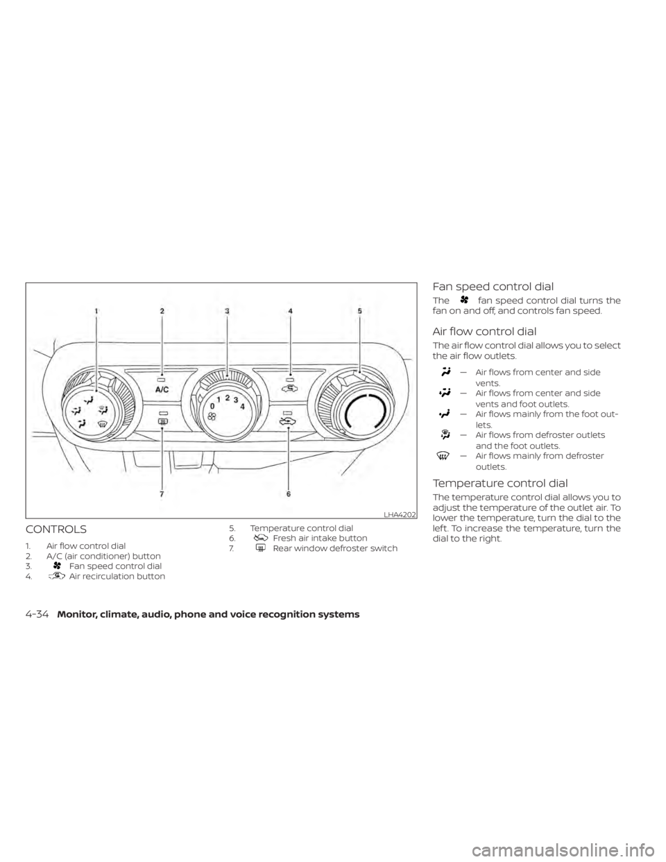
CONTROLS
1. Air flow control dial
2. A/C (air conditioner) button
3.
Fan speed control dial
4.Air recirculation button 5. Temperature control dial
6.
Fresh air intake button
7.Rear window defroster switch
Fan speed control dial
Thefan speed control dial turns the
fan on and off, and controls fan speed.
Air flow control dial
The air flow control dial allows you to select
the air flow outlets.
— Air flows from center and side
vents.
— Air flows from center and sidevents and foot outlets.
— Air flows mainly from the foot out-lets.
— Air flows from defroster outletsand the foot outlets.
— Air flows mainly from defrosteroutlets.
Temperature control dial
The temperature control dial allows you to
adjust the temperature of the outlet air. To
lower the temperature, turn the dial to the
lef t. To increase the temperature, turn the
dial to the right.
LHA4202
4-34Monitor, climate, audio, phone and voice recognition systems
Page 223 of 500
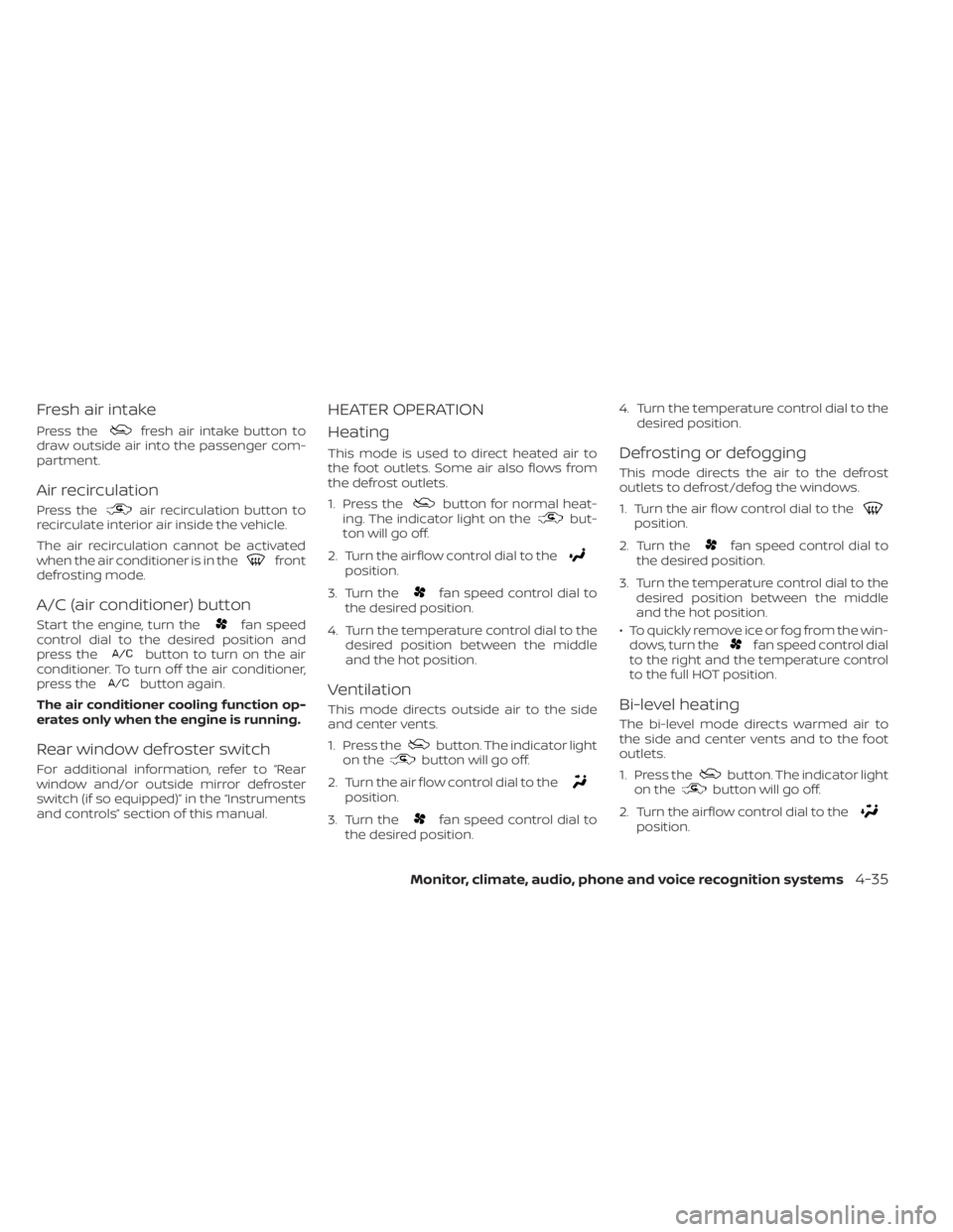
Fresh air intake
Press thefresh air intake button to
draw outside air into the passenger com-
partment.
Air recirculation
Press theair recirculation button to
recirculate interior air inside the vehicle.
The air recirculation cannot be activated
when the air conditioner is in the
front
defrosting mode.
A/C (air conditioner) button
Start the engine, turn thefan speed
control dial to the desired position and
press the
button to turn on the air
conditioner. To turn off the air conditioner,
press the
button again.
The air conditioner cooling function op-
erates only when the engine is running.
Rear window defroster switch
For additional information, refer to “Rear
window and/or outside mirror defroster
switch (if so equipped)” in the “Instruments
and controls” section of this manual.
HEATER OPERATION
Heating
This mode is used to direct heated air to
the foot outlets. Some air also flows from
the defrost outlets.
1. Press the
button for normal heat-
ing. The indicator light on thebut-
ton will go off.
2. Turn the airflow control dial to the
position.
3. Turn the
fan speed control dial to
the desired position.
4. Turn the temperature control dial to the desired position between the middle
and the hot position.
Ventilation
This mode directs outside air to the side
and center vents.
1. Press the
button. The indicator light
on thebutton will go off.
2. Turn the air flow control dial to the
position.
3. Turn the
fan speed control dial to
the desired position. 4. Turn the temperature control dial to the
desired position.
Defrosting or defogging
This mode directs the air to the defrost
outlets to defrost/defog the windows.
1. Turn the air flow control dial to the
position.
2. Turn the
fan speed control dial to
the desired position.
3. Turn the temperature control dial to the desired position between the middle
and the hot position.
• To quickly remove ice or fog from the win- dows, turn the
fan speed control dial
to the right and the temperature control
to the full HOT position.
Bi-level heating
The bi-level mode directs warmed air to
the side and center vents and to the foot
outlets.
1. Press the
button. The indicator light
on thebutton will go off.
2. Turn the airflow control dial to the
position.
Monitor, climate, audio, phone and voice recognition systems4-35
Page 224 of 500
3. Turn thefan speed control dial to
the desired position.
4. Turn the temperature control dial to the desired position.
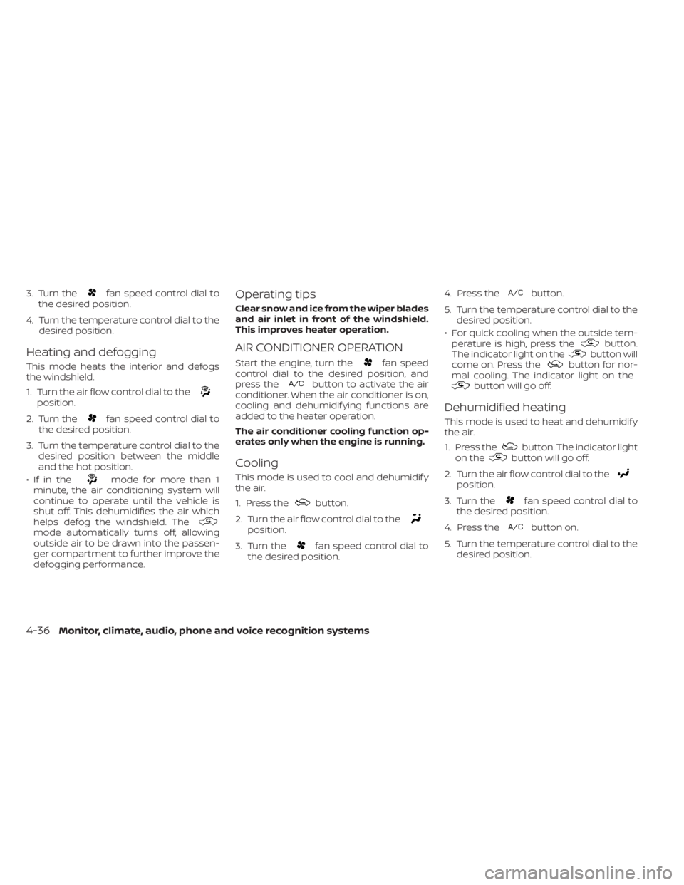
Heating and defogging
This mode heats the interior and defogs
the windshield.
1. Turn the air flow control dial to the
position.
2. Turn the
fan speed control dial to
the desired position.
3. Turn the temperature control dial to the desired position between the middle
and the hot position.
•Ifinthe
mode for more than 1
minute, the air conditioning system will
continue to operate until the vehicle is
shut off. This dehumidifies the air which
helps defog the windshield. The
mode automatically turns off, allowing
outside air to be drawn into the passen-
ger compartment to further improve the
defogging performance.
Operating tips
Clear snow and ice from the wiper blades
and air inlet in front of the windshield.
This improves heater operation.
AIR CONDITIONER OPERATION
Start the engine, turn thefan speed
control dial to the desired position, and
press the
button to activate the air
conditioner. When the air conditioner is on,
cooling and dehumidif ying functions are
added to the heater operation.
The air conditioner cooling function op-
erates only when the engine is running.
Cooling
This mode is used to cool and dehumidif y
the air.
1. Press the
button.
2. Turn the air flow control dial to the
position.
3. Turn the
fan speed control dial to
the desired position. 4. Press the
button.
5. Turn the temperature control dial to the desired position.
• For quick cooling when the outside tem- perature is high, press the
button.
The indicator light on thebutton will
come on. Press thebutton for nor-
mal cooling. The indicator light on the
button will go off.
Dehumidified heating
This mode is used to heat and dehumidif y
the air.
1. Press the
button. The indicator light
on thebutton will go off.
2. Turn the air flow control dial to the
position.
3. Turn the
fan speed control dial to
the desired position.
4. Press the
button on.
5. Turn the temperature control dial to the desired position.
4-36Monitor, climate, audio, phone and voice recognition systems
Page 225 of 500
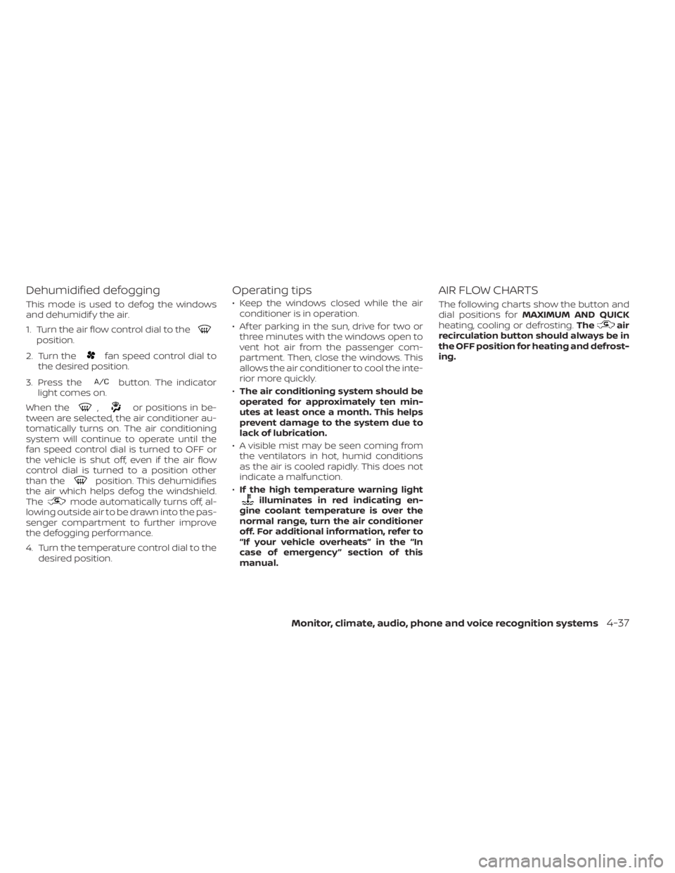
Dehumidified defogging
This mode is used to defog the windows
and dehumidif y the air.
1. Turn the air flow control dial to the
position.
2. Turn the
fan speed control dial to
the desired position.
3. Press the
button. The indicator
light comes on.
When the
,or positions in be-
tween are selected, the air conditioner au-
tomatically turns on. The air conditioning
system will continue to operate until the
fan speed control dial is turned to OFF or
the vehicle is shut off, even if the air flow
control dial is turned to a position other
than the
position. This dehumidifies
the air which helps defog the windshield.
The
mode automatically turns off, al-
lowing outside air to be drawn into the pas-
senger compartment to further improve
the defogging performance.
4. Turn the temperature control dial to the desired position.
Operating tips
• Keep the windows closed while the airconditioner is in operation.
• Af ter parking in the sun, drive for two or three minutes with the windows open to
vent hot air from the passenger com-
partment. Then, close the windows. This
allows the air conditioner to cool the inte-
rior more quickly.
• The air conditioning system should be
operated for approximately ten min-
utes at least once a month. This helps
prevent damage to the system due to
lack of lubrication.
• A visible mist may be seen coming from the ventilators in hot, humid conditions
as the air is cooled rapidly. This does not
indicate a malfunction.
• If the high temperature warning light
illuminates in red indicating en-
gine coolant temperature is over the
normal range, turn the air conditioner
off. For additional information, refer to
“If your vehicle overheats” in the “In
case of emergency ” section of this
manual.
AIR FLOW CHARTS
The following charts show the button and
dial positions for MAXIMUM AND QUICK
heating, cooling or defrosting. The
air
recirculation button should always be in
the OFF position for heating and defrost-
ing.
Monitor, climate, audio, phone and voice recognition systems4-37