NISSAN LATIO 2007 Service Repair Manual
LATIO 2007
NISSAN
NISSAN
https://www.carmanualsonline.info/img/5/57361/w960_57361-0.png
NISSAN LATIO 2007 Service Repair Manual
Trending: parking sensors, fog light bulb, horn, mirror, battery location, navigation, fuel
Page 1781 of 2896
EI-16
FRONT BUMPER
Revision: June 20062007 Versa
INSTALLATION
Installation is in the reverse order of removal.
Page 1782 of 2896
REAR BUMPER
EI-17
C
D
E
F
G
H
J
K
L
MA
B
EI
Revision: June 20062007 Versa
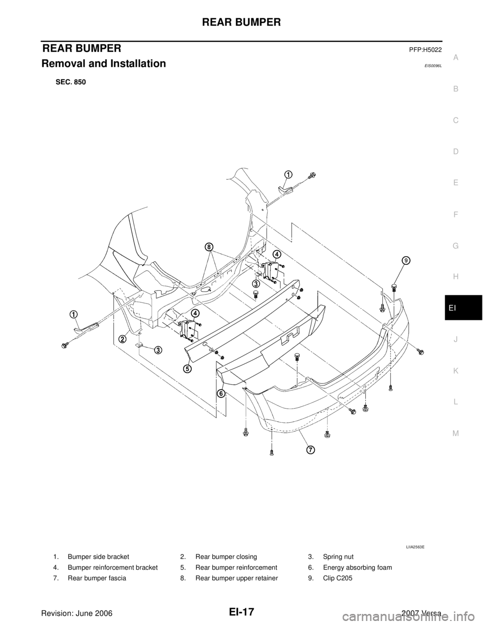
REAR BUMPERPFP:H5022
Removal and InstallationEIS0096L
1. Bumper side bracket 2. Rear bumper closing 3. Spring nut
4. Bumper reinforcement bracket 5. Rear bumper reinforcement 6. Energy absorbing foam
7. Rear bumper fascia 8. Rear bumper upper retainer 9. Clip C205
LIIA2563E
Page 1783 of 2896
EI-18
REAR BUMPER
Revision: June 20062007 Versa
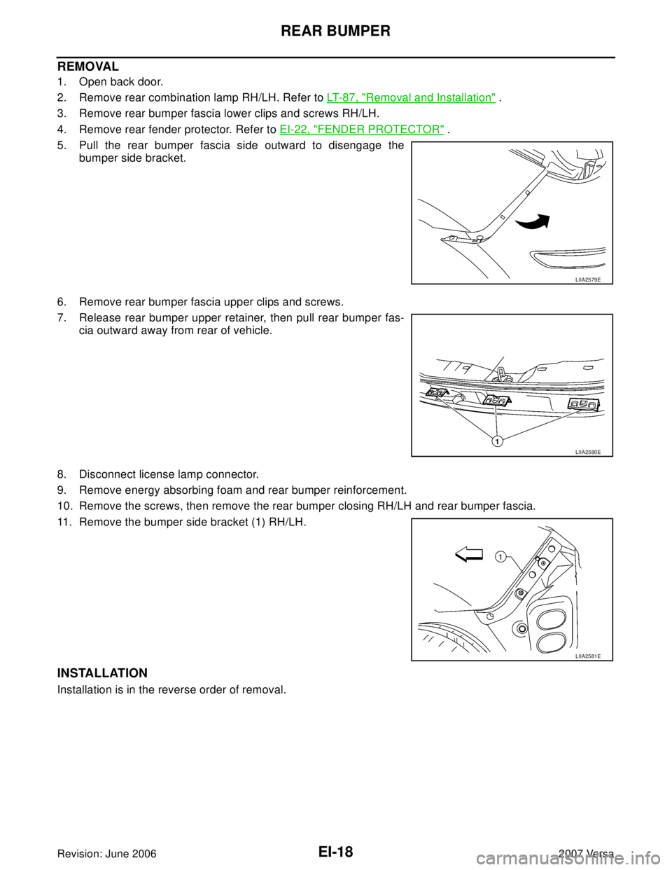
REMOVAL
1. Open back door.
2. Remove rear combination lamp RH/LH. Refer to LT- 8 7 , "
Removal and Installation" .
3. Remove rear bumper fascia lower clips and screws RH/LH.
4. Remove rear fender protector. Refer to EI-22, "
FENDER PROTECTOR" .
5. Pull the rear bumper fascia side outward to disengage the
bumper side bracket.
6. Remove rear bumper fascia upper clips and screws.
7. Release rear bumper upper retainer, then pull rear bumper fas-
cia outward away from rear of vehicle.
8. Disconnect license lamp connector.
9. Remove energy absorbing foam and rear bumper reinforcement.
10. Remove the screws, then remove the rear bumper closing RH/LH and rear bumper fascia.
11. Remove the bumper side bracket (1) RH/LH.
INSTALLATION
Installation is in the reverse order of removal.
LIIA2579E
LIIA2580E
LIIA2581E
Page 1784 of 2896
FRONT GRILLE
EI-19
C
D
E
F
G
H
J
K
L
MA
B
EI
Revision: June 20062007 Versa
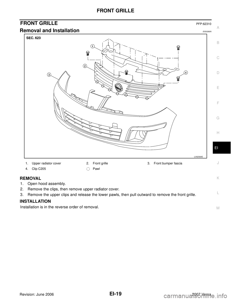
FRONT GRILLEPFP:62310
Removal and InstallationEIS0096N
REMOVAL
1. Open hood assembly.
2. Remove the clips, then remove upper radiator cover.
3. Remove the upper clips and release the lower pawls, then pull outward to remove the front grille.
INSTALLATION
Installation is in the reverse order of removal.
LIIA2564E
1. Upper radiator cover 2. Front grille 3. Front bumper fascia
4. Clip C205 Pawl
Page 1785 of 2896
EI-20
COWL TOP
Revision: June 20062007 Versa
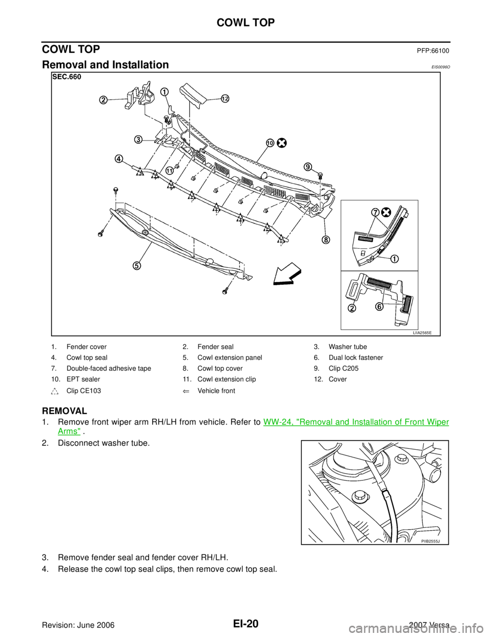
COWL TOPPFP:66100
Removal and InstallationEIS0096O
REMOVAL
1. Remove front wiper arm RH/LH from vehicle. Refer to WW-24, "Removal and Installation of Front Wiper
Arms" .
2. Disconnect washer tube.
3. Remove fender seal and fender cover RH/LH.
4. Release the cowl top seal clips, then remove cowl top seal.
LIIA2565E
1. Fender cover 2. Fender seal 3. Washer tube
4. Cowl top seal 5. Cowl extension panel 6. Dual lock fastener
7. Double-faced adhesive tape 8. Cowl top cover 9. Clip C205
10. EPT sealer 11. Cowl extension clip 12. Cover
Clip CE103⇐Vehicle front
PIIB2555J
Page 1786 of 2896
COWL TOP
EI-21
C
D
E
F
G
H
J
K
L
MA
B
EI
Revision: June 20062007 Versa
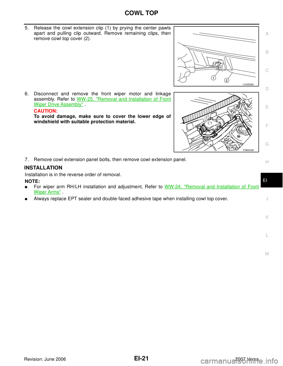
5. Release the cowl extension clip (1) by prying the center pawls
apart and pulling clip outward. Remove remaining clips, then
remove cowl top cover (2).
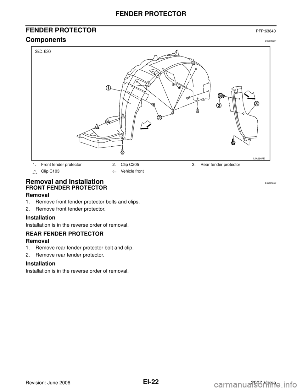
6. Disconnect and remove the front wiper motor and linkage
assembly. Refer to WW-25, "
Removal and Installation of Front
Wiper Drive Assembly" .
CAUTION:
To avoid damage, make sure to cover the lower edge of
windshield with suitable protection material.
7. Remove cowl extension panel bolts, then remove cowl extension panel.
INSTALLATION
Installation is in the reverse order of removal.
NOTE:
�For wiper arm RH/LH installation and adjustment, Refer to WW-24, "Removal and Installation of Front
Wiper Arms" .
�Always replace EPT sealer and double-faced adhesive tape when installing cowl top cover.
LIIA2566E
PIIB6038E
Page 1787 of 2896
EI-22
FENDER PROTECTOR
Revision: June 20062007 Versa
FENDER PROTECTORPFP:63840
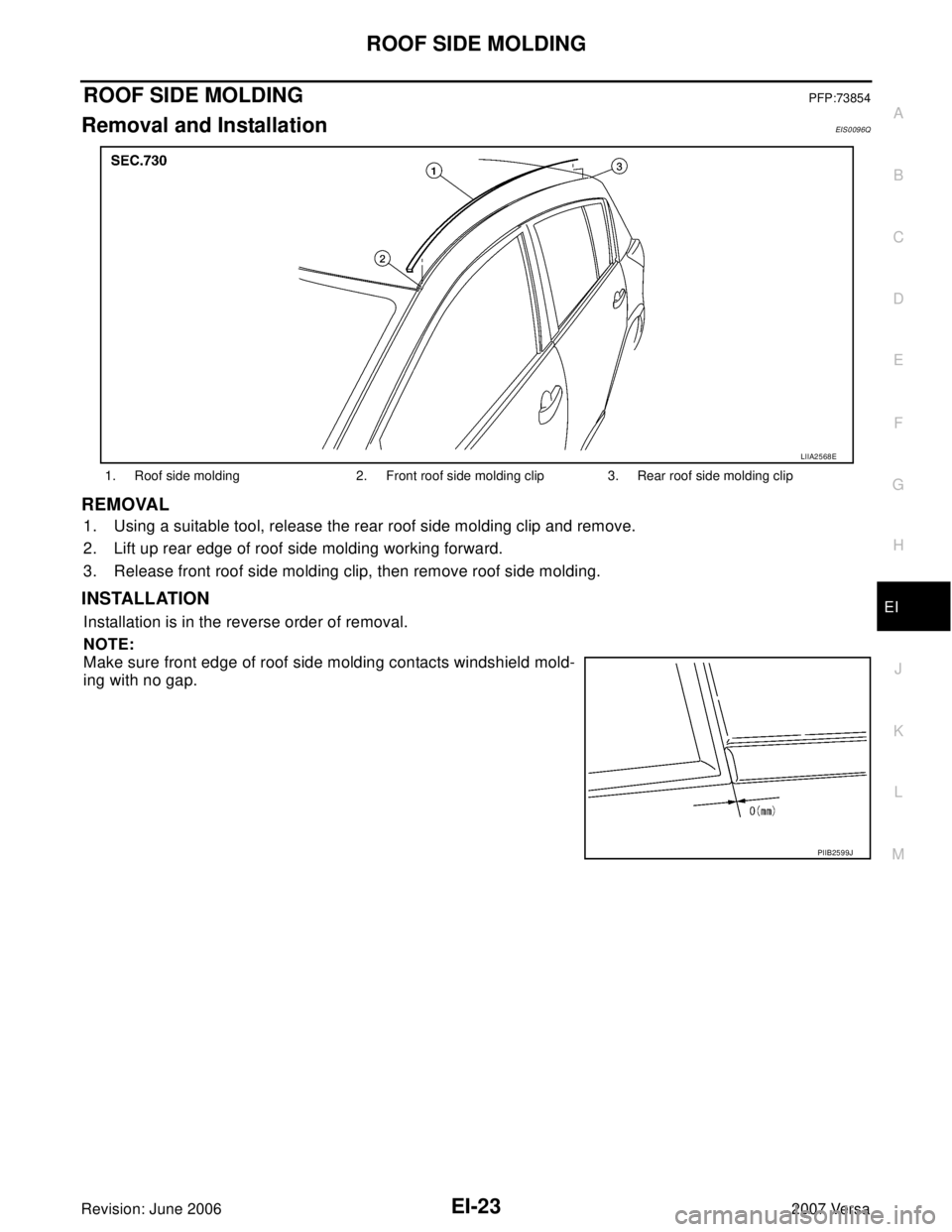
ComponentsEIS0096P
Removal and InstallationEIS009AE
FRONT FENDER PROTECTOR
Removal
1. Remove front fender protector bolts and clips.
2. Remove front fender protector.
Installation
Installation is in the reverse order of removal.
REAR FENDER PROTECTOR
Removal
1. Remove rear fender protector bolt and clip.
2. Remove rear fender protector.
Installation
Installation is in the reverse order of removal.
1. Front fender protector 2. Clip C205 3. Rear fender protector
Clip C103⇐Vehicle front
LIIA2567E
Page 1788 of 2896
ROOF SIDE MOLDING
EI-23
C
D
E
F
G
H
J
K
L
MA
B
EI
Revision: June 20062007 Versa
ROOF SIDE MOLDINGPFP:73854
Removal and InstallationEIS0096Q
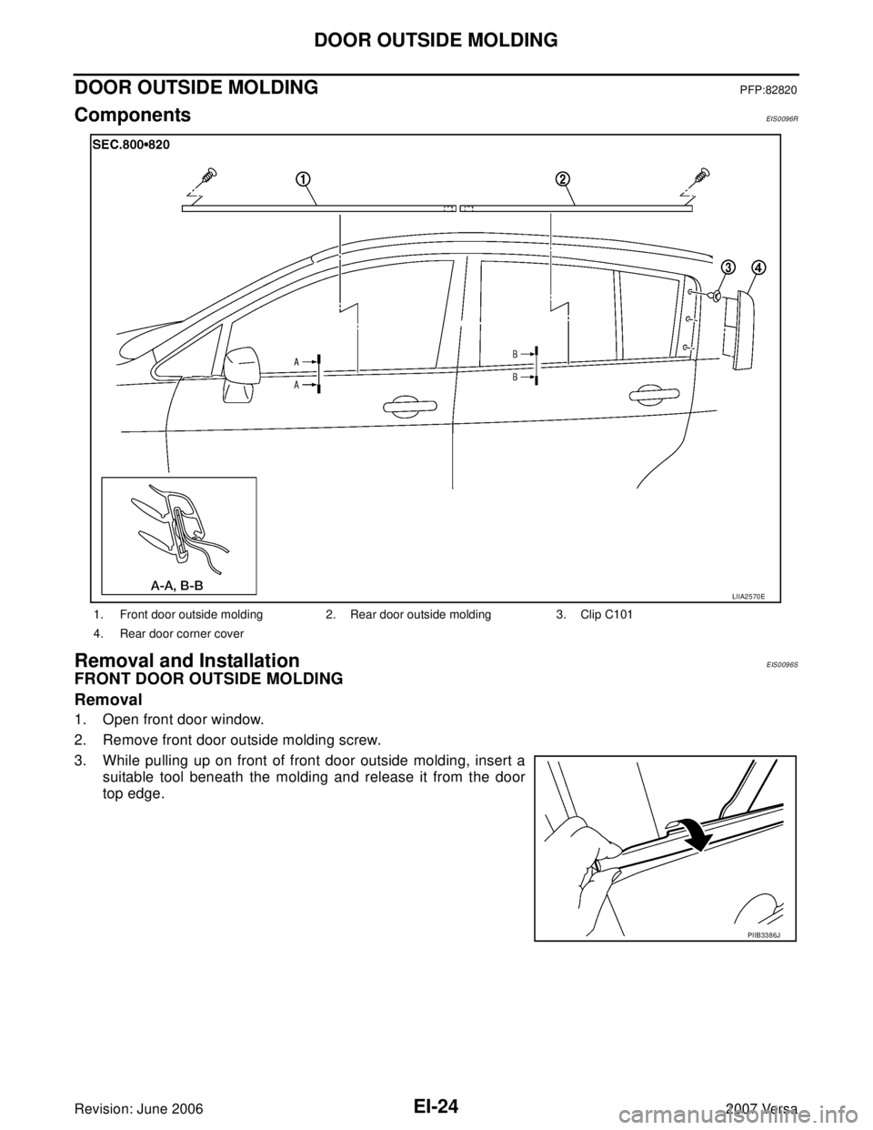
REMOVAL
1. Using a suitable tool, release the rear roof side molding clip and remove.
2. Lift up rear edge of roof side molding working forward.
3. Release front roof side molding clip, then remove roof side molding.
INSTALLATION
Installation is in the reverse order of removal.
NOTE:
Make sure front edge of roof side molding contacts windshield mold-
ing with no gap.
1. Roof side molding 2. Front roof side molding clip 3. Rear roof side molding clip
LIIA2568E
PIIB2599J
Page 1789 of 2896
EI-24
DOOR OUTSIDE MOLDING
Revision: June 20062007 Versa
DOOR OUTSIDE MOLDING PFP:82820
ComponentsEIS0096R
Removal and InstallationEIS0096S
FRONT DOOR OUTSIDE MOLDING
Removal
1. Open front door window.
2. Remove front door outside molding screw.
3. While pulling up on front of front door outside molding, insert a
suitable tool beneath the molding and release it from the door
top edge.
1. Front door outside molding 2. Rear door outside molding 3. Clip C101
4. Rear door corner cover
LIIA2570E
PIIB3386J
Page 1790 of 2896
DOOR OUTSIDE MOLDING
EI-25
C
D
E
F
G
H
J
K
L
MA
B
EI
Revision: June 20062007 Versa
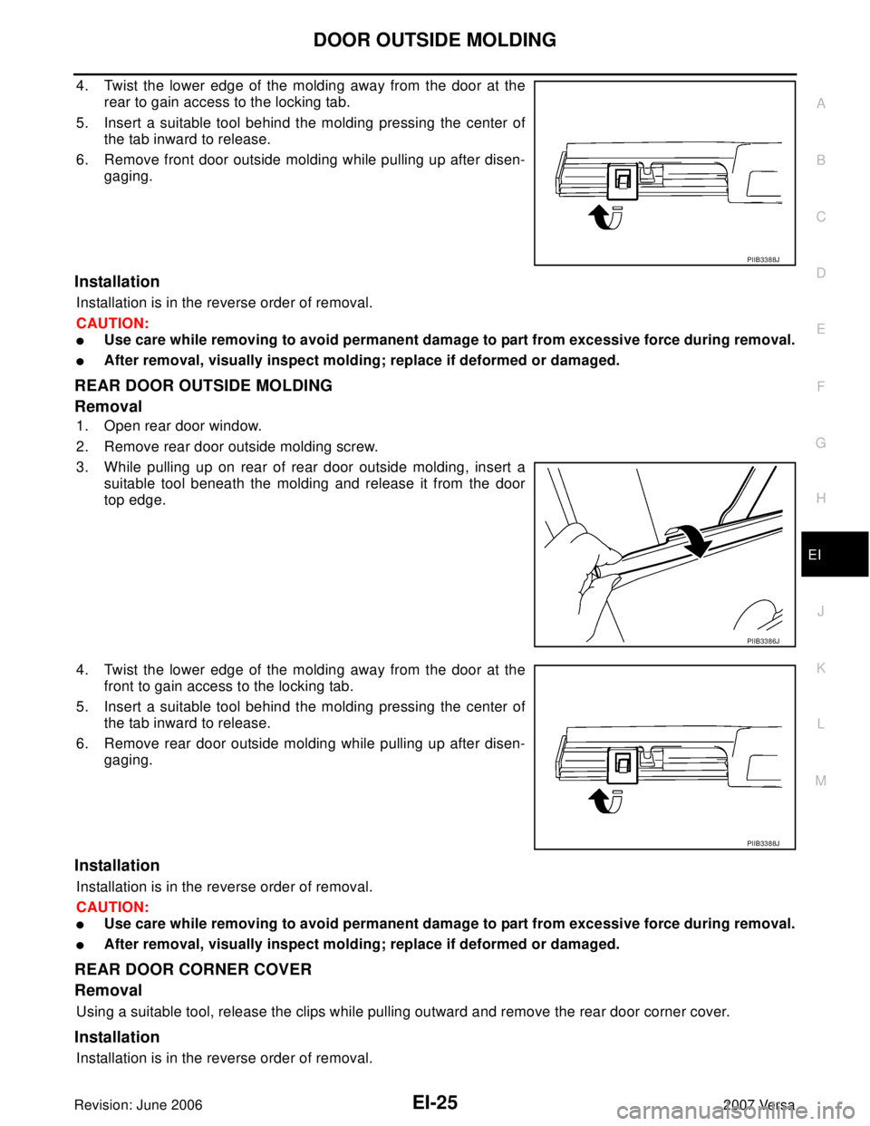
4. Twist the lower edge of the molding away from the door at the
rear to gain access to the locking tab.
5. Insert a suitable tool behind the molding pressing the center of
the tab inward to release.
6. Remove front door outside molding while pulling up after disen-
gaging.
Installation
Installation is in the reverse order of removal.
CAUTION:
�Use care while removing to avoid permanent damage to part from excessive force during removal.
�After removal, visually inspect molding; replace if deformed or damaged.
REAR DOOR OUTSIDE MOLDING
Removal
1. Open rear door window.
2. Remove rear door outside molding screw.
3. While pulling up on rear of rear door outside molding, insert a
suitable tool beneath the molding and release it from the door
top edge.
4. Twist the lower edge of the molding away from the door at the
front to gain access to the locking tab.
5. Insert a suitable tool behind the molding pressing the center of
the tab inward to release.
6. Remove rear door outside molding while pulling up after disen-
gaging.
Installation
Installation is in the reverse order of removal.
CAUTION:
�Use care while removing to avoid permanent damage to part from excessive force during removal.
�After removal, visually inspect molding; replace if deformed or damaged.
REAR DOOR CORNER COVER
Removal
Using a suitable tool, release the clips while pulling outward and remove the rear door corner cover.
Installation
Installation is in the reverse order of removal.
PIIB3388J
PIIB3386J
PIIB3388J
Trending: warning light, timing belt, run flat, parking sensors, gas type, tire type, jacking

