NISSAN LATIO 2007 Service Repair Manual
Manufacturer: NISSAN, Model Year: 2007, Model line: LATIO, Model: NISSAN LATIO 2007Pages: 2896, PDF Size: 64.73 MB
Page 671 of 2896
BL-182
BACK DOOR LOCK
Revision: June 20062007 Versa
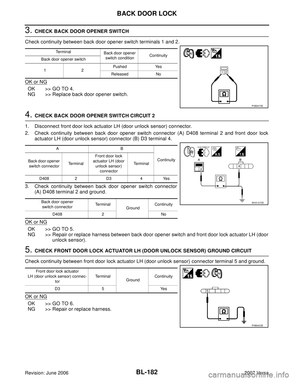
3. CHECK BACK DOOR OPENER SWITCH
Check continuity between back door opener switch terminals 1 and 2.
OK or NG
OK >> GO TO 4.
NG >> Replace back door opener switch.
4. CHECK BACK DOOR OPENER SWITCH CIRCUIT 2
1. Disconnect front door lock actuator LH (door unlock sensor) connector.
2. Check continuity between back door opener switch connector (A) D408 terminal 2 and front door lock
actuator LH (door unlock sensor) connector (B) D3 terminal 4.
3. Check continuity between back door opener switch connector
(A) D408 terminal 2 and ground.
OK or NG
OK >> GO TO 5.
NG >> Repair or replace harness between back door opener switch and front door lock actuator LH (door
unlock sensor).
5. CHECK FRONT DOOR LOCK ACTUATOR LH (DOOR UNLOCK SENSOR) GROUND CIRCUIT
Check continuity between front door lock actuator LH (door unlock sensor) connector terminal 5 and ground.
OK or NG
OK >> GO TO 6.
NG >> Repair or replace harness.
Te r m i n a l
Back door opener
switch conditionContinuity
Back door opener switch
12Pushed Yes
Released No
PIIB6470E
AB
Continuity
Back door opener
switch connectorTe r m i n a lFront door lock
actuator LH (door
unlock sensor)
connectorTe r m i n a l
D408 2 D3 4 Yes
Back door opener
switch connectorTe r m i n a l
GroundContinuity
D408 2 No
WIIA1272E
Front door lock actuator
LH (door unlock sensor) connec-
torTe r m i n a l
GroundContinuity
D3 5 Yes
PIIB6423E
Page 672 of 2896
BACK DOOR LOCK
BL-183
C
D
E
F
G
H
J
K
L
MA
B
BL
Revision: June 20062007 Versa
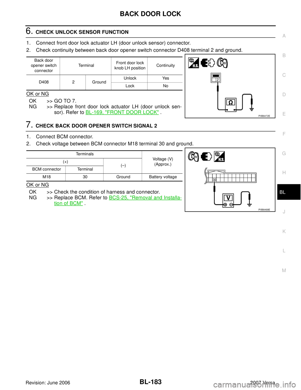
6. CHECK UNLOCK SENSOR FUNCTION
1. Connect front door lock actuator LH (door unlock sensor) connector.
2. Check continuity between back door opener switch connector D408 terminal 2 and ground.
OK or NG
OK >> GO TO 7.
NG >> Replace front door lock actuator LH (door unlock sen-
sor). Refer to BL-169, "
FRONT DOOR LOCK" .
7. CHECK BACK DOOR OPENER SWITCH SIGNAL 2
1. Connect BCM connector.
2. Check voltage between BCM connector M18 terminal 30 and ground.
OK or NG
OK >> Check the condition of harness and connector.
NG >> Replace BCM. Refer to BCS-25, "
Removal and Installa-
tion of BCM" .
Back door
opener switch
connectorTe r m i n a lFront door lock
knob LH positionContinuity
D408 2 GroundUnlock Yes
Lock No
PIIB6472E
Te r m i n a l s
Voltage (V)
(Approx.) (+)
(–)
BCM connector Terminal
M18 30 Ground Battery voltage
PIIB6468E
Page 673 of 2896
BL-184
BACK DOOR LOCK
Revision: June 20062007 Versa
Check Back Door Opener Switch Circuit (Without Intelligent Key, With Power
Windows)
EIS009DV
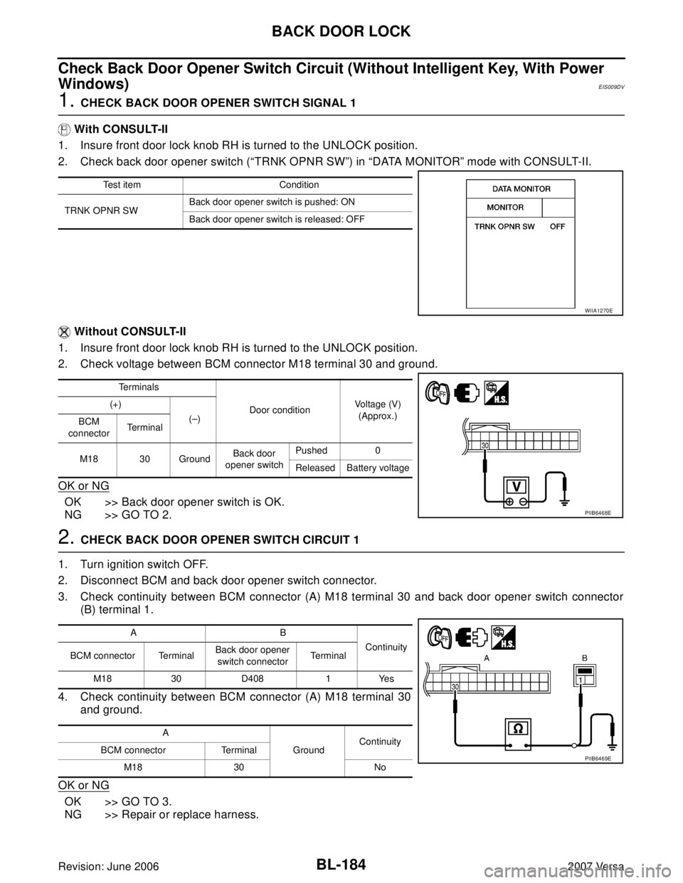
1. CHECK BACK DOOR OPENER SWITCH SIGNAL 1
With CONSULT-II
1. Insure front door lock knob RH is turned to the UNLOCK position.
2. Check back door opener switch (“TRNK OPNR SW”) in “DATA MONITOR” mode with CONSULT-II.
Without CONSULT-II
1. Insure front door lock knob RH is turned to the UNLOCK position.
2. Check voltage between BCM connector M18 terminal 30 and ground.
OK or NG
OK >> Back door opener switch is OK.
NG >> GO TO 2.
2. CHECK BACK DOOR OPENER SWITCH CIRCUIT 1
1. Turn ignition switch OFF.
2. Disconnect BCM and back door opener switch connector.
3. Check continuity between BCM connector (A) M18 terminal 30 and back door opener switch connector
(B) terminal 1.
4. Check continuity between BCM connector (A) M18 terminal 30
and ground.
OK or NG
OK >> GO TO 3.
NG >> Repair or replace harness.
Test item Condition
TRNK OPNR SWBack door opener switch is pushed: ON
Back door opener switch is released: OFF
WIIA1270E
Te r m i n a l s
Door conditionVoltage (V)
(Approx.) (+)
(–)
BCM
connectorTerminal
M18 30 GroundBack door
opener switchPushed 0
Released Battery voltage
PIIB6468E
AB
Continuity
BCM connector TerminalBack door opener
switch connectorTe r m i n a l
M18 30 D408 1 Yes
A
GroundContinuity
BCM connector Terminal
M18 30 No
PIIB6469E
Page 674 of 2896
BACK DOOR LOCK
BL-185
C
D
E
F
G
H
J
K
L
MA
B
BL
Revision: June 20062007 Versa
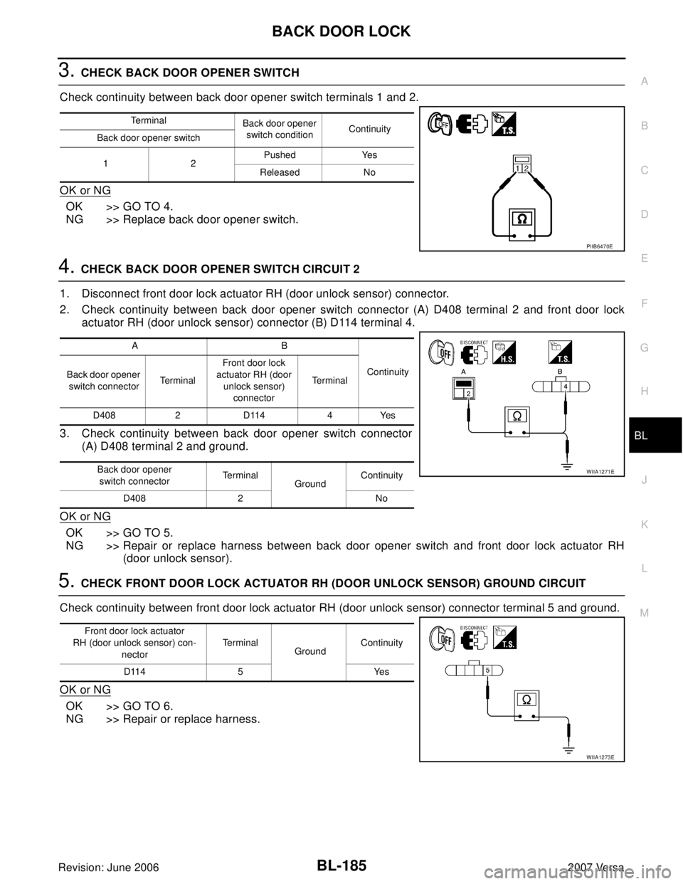
3. CHECK BACK DOOR OPENER SWITCH
Check continuity between back door opener switch terminals 1 and 2.
OK or NG
OK >> GO TO 4.
NG >> Replace back door opener switch.
4. CHECK BACK DOOR OPENER SWITCH CIRCUIT 2
1. Disconnect front door lock actuator RH (door unlock sensor) connector.
2. Check continuity between back door opener switch connector (A) D408 terminal 2 and front door lock
actuator RH (door unlock sensor) connector (B) D114 terminal 4.
3. Check continuity between back door opener switch connector
(A) D408 terminal 2 and ground.
OK or NG
OK >> GO TO 5.
NG >> Repair or replace harness between back door opener switch and front door lock actuator RH
(door unlock sensor).
5. CHECK FRONT DOOR LOCK ACTUATOR RH (DOOR UNLOCK SENSOR) GROUND CIRCUIT
Check continuity between front door lock actuator RH (door unlock sensor) connector terminal 5 and ground.
OK or NG
OK >> GO TO 6.
NG >> Repair or replace harness.
Terminal
Back door opener
switch conditionContinuity
Back door opener switch
12Pushed Yes
Released No
PIIB6470E
AB
Continuity
Back door opener
switch connectorTe r m i n a lFront door lock
actuator RH (door
unlock sensor)
connectorTe r m i n a l
D408 2 D114 4 Yes
Back door opener
switch connectorTe r m i n a l
GroundContinuity
D408 2 No
WIIA1271E
Front door lock actuator
RH (door unlock sensor) con-
nectorTe r m i n a l
GroundContinuity
D114 5 Yes
WIIA1273E
Page 675 of 2896
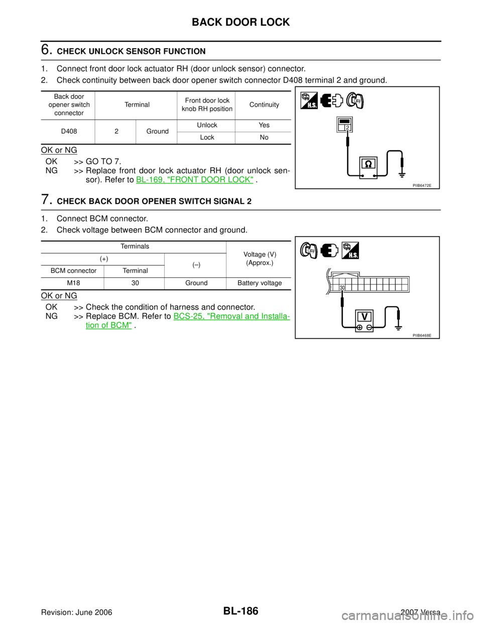
BL-186
BACK DOOR LOCK
Revision: June 20062007 Versa
6. CHECK UNLOCK SENSOR FUNCTION
1. Connect front door lock actuator RH (door unlock sensor) connector.
2. Check continuity between back door opener switch connector D408 terminal 2 and ground.
OK or NG
OK >> GO TO 7.
NG >> Replace front door lock actuator RH (door unlock sen-
sor). Refer to BL-169, "
FRONT DOOR LOCK" .
7. CHECK BACK DOOR OPENER SWITCH SIGNAL 2
1. Connect BCM connector.
2. Check voltage between BCM connector and ground.
OK or NG
OK >> Check the condition of harness and connector.
NG >> Replace BCM. Refer to BCS-25, "
Removal and Installa-
tion of BCM" .
Back door
opener switch
connectorTe r m i n a lFront door lock
knob RH positionContinuity
D408 2 GroundUnlock Yes
Lock No
PIIB6472E
Te r m i n a l s
Voltage (V)
(Approx.) (+)
(–)
BCM connector Terminal
M18 30 Ground Battery voltage
PIIB6468E
Page 676 of 2896
BACK DOOR LOCK
BL-187
C
D
E
F
G
H
J
K
L
MA
B
BL
Revision: June 20062007 Versa
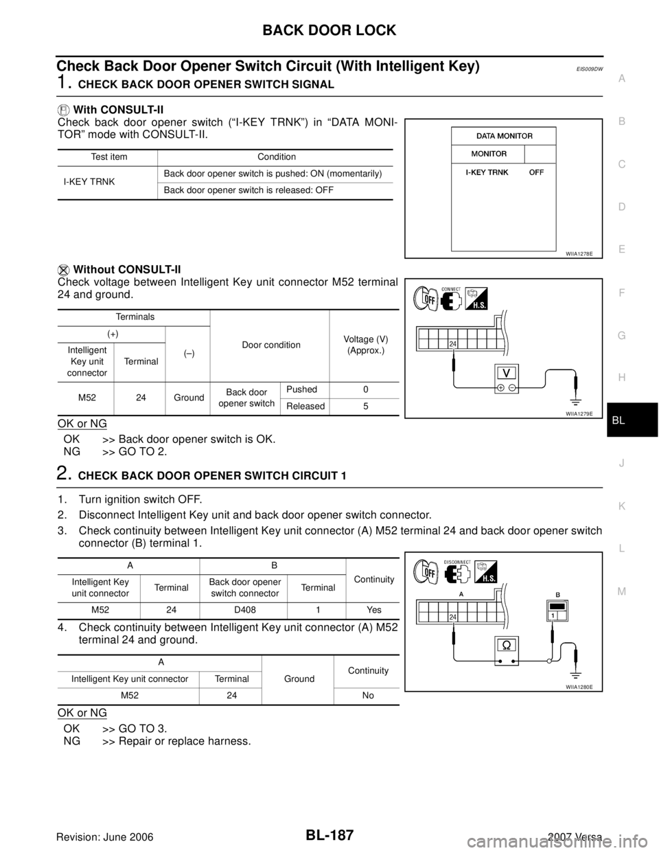
Check Back Door Opener Switch Circuit (With Intelligent Key)EIS009DW
1. CHECK BACK DOOR OPENER SWITCH SIGNAL
With CONSULT-II
Check back door opener switch (“I-KEY TRNK”) in “DATA MONI-
TOR” mode with CONSULT-II.
Without CONSULT-II
Check voltage between Intelligent Key unit connector M52 terminal
24 and ground.
OK or NG
OK >> Back door opener switch is OK.
NG >> GO TO 2.
2. CHECK BACK DOOR OPENER SWITCH CIRCUIT 1
1. Turn ignition switch OFF.
2. Disconnect Intelligent Key unit and back door opener switch connector.
3. Check continuity between Intelligent Key unit connector (A) M52 terminal 24 and back door opener switch
connector (B) terminal 1.
4. Check continuity between Intelligent Key unit connector (A) M52
terminal 24 and ground.
OK or NG
OK >> GO TO 3.
NG >> Repair or replace harness.
Test item Condition
I-KEY TRNKBack door opener switch is pushed: ON (momentarily)
Back door opener switch is released: OFF
Te r m i n a l s
Door conditionVoltage (V)
(Approx.) (+)
(–) Intelligent
Key unit
connectorTe r m i n a l
M52 24 GroundBack door
opener switchPushed 0
Released 5
WIIA1278E
WIIA1279E
AB
Continuity
Intelligent Key
unit connectorTe r m i n a lBack door opener
switch connectorTe r m i n a l
M52 24 D408 1 Yes
A
GroundContinuity
Intelligent Key unit connector Terminal
M52 24 No
WIIA1280E
Page 677 of 2896
BL-188
BACK DOOR LOCK
Revision: June 20062007 Versa
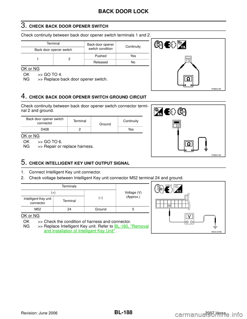
3. CHECK BACK DOOR OPENER SWITCH
Check continuity between back door opener switch terminals 1 and 2.
OK or NG
OK >> GO TO 4.
NG >> Replace back door opener switch.
4. CHECK BACK DOOR OPENER SWITCH GROUND CIRCUIT
Check continuity between back door opener switch connector termi-
nal 2 and ground.
OK or NG
OK >> GO TO 6.
NG >> Repair or replace harness.
5. CHECK INTELLIGENT KEY UNIT OUTPUT SIGNAL
1. Connect Intelligent Key unit connector.
2. Check voltage between Intelligent Key unit connector M52 terminal 24 and ground.
OK or NG
OK >> Check the condition of harness and connector.
NG >> Replace Intelligent Key unit. Refer to BL-160, "
Removal
and Installation of Intelligent Key Unit" .
Te r m i n a l
Back door opener
switch conditionContinuity
Back door opener switch
12Pushed Yes
Released No
PIIB6470E
Back door opener switch
connectorTe r m i n a l
GroundContinuity
D408 2 Yes
PIIB6472E
Te r m i n a l s
Voltage (V)
(Approx.) (+)
(–)
Intelligent Key unit
connectorTerminal
M52 24 Ground 5
WIIA1279E
Page 678 of 2896
BACK DOOR LOCK
BL-189
C
D
E
F
G
H
J
K
L
MA
B
BL
Revision: June 20062007 Versa
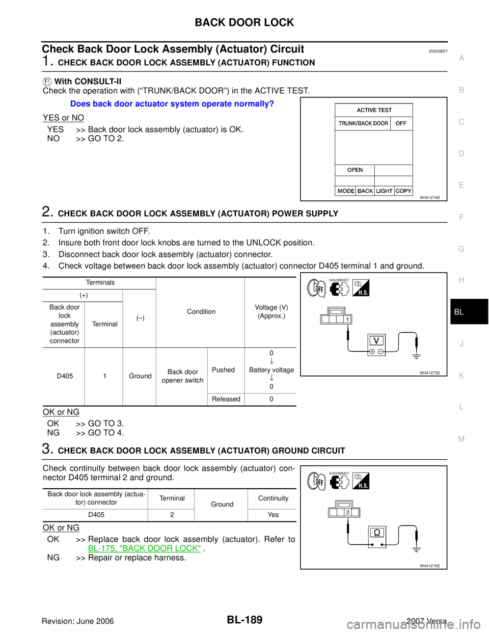
Check Back Door Lock Assembly (Actuator) CircuitEIS0 09 DT
1. CHECK BACK DOOR LOCK ASSEMBLY (ACTUATOR) FUNCTION
With CONSULT-II
Check the operation with (“TRUNK/BACK DOOR”) in the ACTIVE TEST.
YES or NO
YES >> Back door lock assembly (actuator) is OK.
NO >> GO TO 2.
2. CHECK BACK DOOR LOCK ASSEMBLY (ACTUATOR) POWER SUPPLY
1. Turn ignition switch OFF.
2. Insure both front door lock knobs are turned to the UNLOCK position.
3. Disconnect back door lock assembly (actuator) connector.
4. Check voltage between back door lock assembly (actuator) connector D405 terminal 1 and ground.
OK or NG
OK >> GO TO 3.
NG >> GO TO 4.
3. CHECK BACK DOOR LOCK ASSEMBLY (ACTUATOR) GROUND CIRCUIT
Check continuity between back door lock assembly (actuator) con-
nector D405 terminal 2 and ground.
OK or NG
OK >> Replace back door lock assembly (actuator). Refer to
BL-175, "
BACK DOOR LOCK" .
NG >> Repair or replace harness.Does back door actuator system operate normally?
WIIA1274E
Te r m i n a l s
ConditionVoltage (V)
(Approx.) (+)
(–) Back door
lock
assembly
(actuator)
connectorTe r m i n a l
D405 1 GroundBack door
opener switchPushed0
↓
Battery voltage
↓
0
Released 0
WIIA1275E
Back door lock assembly (actua-
tor) connectorTe r m i n a l
GroundContinuity
D405 2 Yes
WIIA1276E
Page 679 of 2896
BL-190
BACK DOOR LOCK
Revision: June 20062007 Versa
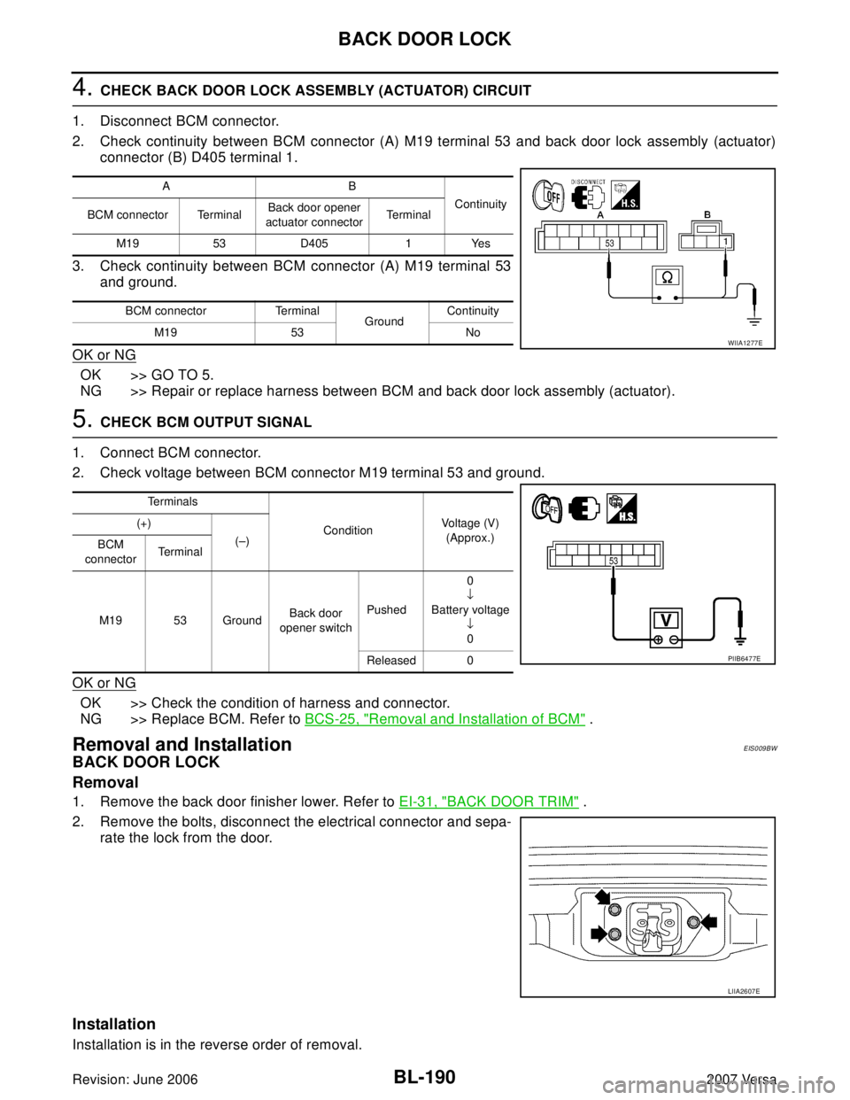
4. CHECK BACK DOOR LOCK ASSEMBLY (ACTUATOR) CIRCUIT
1. Disconnect BCM connector.
2. Check continuity between BCM connector (A) M19 terminal 53 and back door lock assembly (actuator)
connector (B) D405 terminal 1.
3. Check continuity between BCM connector (A) M19 terminal 53
and ground.
OK or NG
OK >> GO TO 5.
NG >> Repair or replace harness between BCM and back door lock assembly (actuator).
5. CHECK BCM OUTPUT SIGNAL
1. Connect BCM connector.
2. Check voltage between BCM connector M19 terminal 53 and ground.
OK or NG
OK >> Check the condition of harness and connector.
NG >> Replace BCM. Refer to BCS-25, "
Removal and Installation of BCM" .
Removal and InstallationEIS009BW
BACK DOOR LOCK
Removal
1. Remove the back door finisher lower. Refer to EI-31, "BACK DOOR TRIM" .
2. Remove the bolts, disconnect the electrical connector and sepa-
rate the lock from the door.
Installation
Installation is in the reverse order of removal.
AB
Continuity
BCM connector TerminalBack door opener
actuator connectorTe r m i n a l
M19 53 D405 1 Yes
BCM connector Terminal
GroundContinuity
M19 53 No
WIIA1277E
Te r m i n a l s
ConditionVoltage (V)
(Approx.) (+)
(–)
BCM
connectorTerminal
M19 53 GroundBack door
opener switchPushed0
↓
Battery voltage
↓
0
Released 0
PIIB6477E
LIIA2607E
Page 680 of 2896
BACK DOOR LOCK
BL-191
C
D
E
F
G
H
J
K
L
MA
B
BL
Revision: June 20062007 Versa
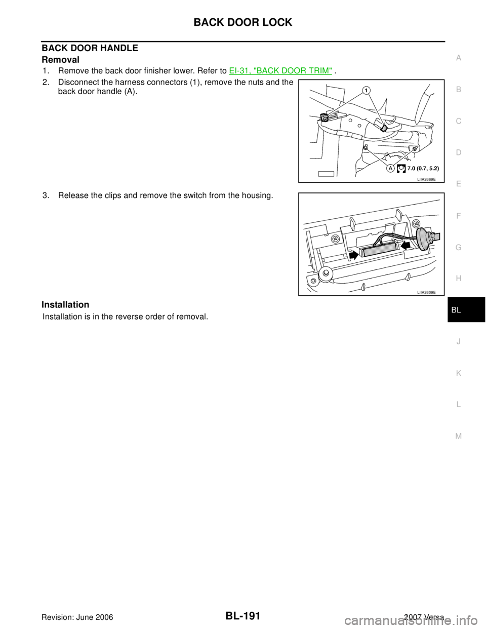
BACK DOOR HANDLE
Removal
1. Remove the back door finisher lower. Refer to EI-31, "BACK DOOR TRIM" .
2. Disconnect the harness connectors (1), remove the nuts and the
back door handle (A).
3. Release the clips and remove the switch from the housing.
Installation
Installation is in the reverse order of removal.
LIIA2669E
LIIA2609E