change time NISSAN LATIO 2007 Service Manual PDF
[x] Cancel search | Manufacturer: NISSAN, Model Year: 2007, Model line: LATIO, Model: NISSAN LATIO 2007Pages: 2896, PDF Size: 64.73 MB
Page 2747 of 2896

TROUBLE DIAGNOSIS
SRS-19
C
D
E
F
G
I
J
K
L
MA
B
SRS
Revision: June 20062007 Versa
CONSULT-II Function (AIR BAG)EHS001V1
CONSULT-II can display each diagnostic item using the diagnostic test modes shown following.
HOW TO CHANGE BETWEEN SELF-DIAGNOSIS MODE AND USER MODE WITH CONSULT-II
From User Mode to Diagnosis Mode
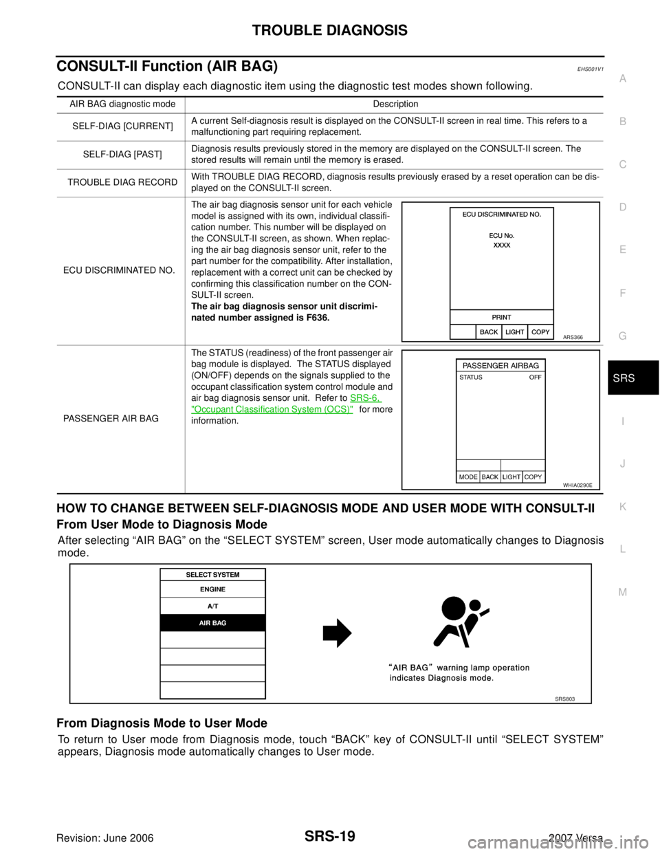
After selecting “AIR BAG” on the “SELECT SYSTEM” screen, User mode automatically changes to Diagnosis
mode.
From Diagnosis Mode to User Mode
To return to User mode from Diagnosis mode, touch “BACK” key of CONSULT-II until “SELECT SYSTEM”
appears, Diagnosis mode automatically changes to User mode.
AIR BAG diagnostic mode Description
SELF-DIAG [CURRENT]A current Self-diagnosis result is displayed on the CONSULT-II screen in real time. This refers to a
malfunctioning part requiring replacement.
SELF-DIAG [PAST]Diagnosis results previously stored in the memory are displayed on the CONSULT-II screen. The
stored results will remain until the memory is erased.
TROUBLE DIAG RECORDWith TROUBLE DIAG RECORD, diagnosis results previously erased by a reset operation can be dis-
played on the CONSULT-II screen.
ECU DISCRIMINATED NO.The air bag diagnosis sensor unit for each vehicle
model is assigned with its own, individual classifi-
cation number. This number will be displayed on
the CONSULT-II screen, as shown. When replac-
ing the air bag diagnosis sensor unit, refer to the
part number for the compatibility. After installation,
replacement with a correct unit can be checked by
confirming this classification number on the CON-
SULT-II screen.
The air bag diagnosis sensor unit discrimi-
nated number assigned is F636.
PASSENGER AIR BAGThe STATUS (readiness) of the front passenger air
bag module is displayed. The STATUS displayed
(ON/OFF) depends on the signals supplied to the
occupant classification system control module and
air bag diagnosis sensor unit. Refer to SRS-6,
"Occupant Classification System (OCS)" f o r mo re
information.
ARS3 66
WHIA0290E
SRS8 03
Page 2749 of 2896

TROUBLE DIAGNOSIS
SRS-21
C
D
E
F
G
I
J
K
L
MA
B
SRS
Revision: June 20062007 Versa
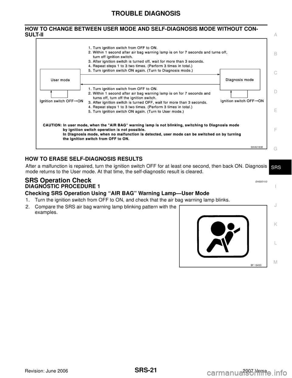
HOW TO CHANGE BETWEEN USER MODE AND SELF-DIAGNOSIS MODE WITHOUT CON-
SULT-II
HOW TO ERASE SELF-DIAGNOSIS RESULTS
After a malfunction is repaired, turn the ignition switch OFF for at least one second, then back ON. Diagnosis
mode returns to the User mode. At that time, the self-diagnostic result is cleared.
SRS Operation CheckEHS001V3
DIAGNOSTIC PROCEDURE 1
Checking SRS Operation Using “AIR BAG” Warning Lamp—User Mode
1. Turn the ignition switch from OFF to ON, and check that the air bag warning lamp blinks.
2. Compare the SRS air bag warning lamp blinking pattern with the
examples.
SHIA0183E
BF-1845D
Page 2797 of 2896
![NISSAN LATIO 2007 Service Manual PDF TROUBLE DIAGNOSIS
STC-11
[EPS]
C
D
E
F
H
I
J
K
L
MA
B
STC
Revision: June 20062007 Versa
EPS Control Unit Input/Output Signal Reference ValuesUGS0007X
SPECIFICATIONS WITH CONSULT-II
CAUTION:
The output NISSAN LATIO 2007 Service Manual PDF TROUBLE DIAGNOSIS
STC-11
[EPS]
C
D
E
F
H
I
J
K
L
MA
B
STC
Revision: June 20062007 Versa
EPS Control Unit Input/Output Signal Reference ValuesUGS0007X
SPECIFICATIONS WITH CONSULT-II
CAUTION:
The output](/img/5/57361/w960_57361-2796.png)
TROUBLE DIAGNOSIS
STC-11
[EPS]
C
D
E
F
H
I
J
K
L
MA
B
STC
Revision: June 20062007 Versa
EPS Control Unit Input/Output Signal Reference ValuesUGS0007X
SPECIFICATIONS WITH CONSULT-II
CAUTION:
The output signal indicates the EPS control unit calculation date. The normal values will be displayed
even in the event that the output circuit (harness) is open.
*1 : In the front of the value, “L” is displayed at steering left and “R” is displayed at steering right.
*2 : Almost in accordance with the value of “MOTOR SIG”. It is not a malfunction though these values are not accorded when steering
quickly.
*3 : It is not a malfunction, though it might not be corresponding just after ignition switch is turned ON.
*4 : It turns to OFF after waiting for a short period of time.Monitor item (Unit) Content Condition Display value
MOTOR VOL (V)Power supply voltage for
EPS control unitIgnition switch: ON Battery voltage
TORQUE SENSOR (Nm)Steering wheel turning
forceEngine runningSteering wheel: Not
steering (There is no
steering force) 0.00 Nm
Steering wheel: Steer-
ing0 – 8.19 Nm
*1 (The value
is changed according to
steering left or right)
MOTOR SIG (A)Command current to EPS
motorEngine runningSteering wheel: Not
steering (There is no
steering force)0.00 A
Steering wheel: Steer-
ing0 – 65.00 A (The value is
changed according to
steering left or right)
MOTOR CURRENT (A)Consumption current of
EPS motorEngine runningSteering wheel: Not
steering (There is no
steering force)0.00 A
Steering wheel: Steer-
ing0 – 65.00 A
*2 (The value
is changed according to
steering left or right)
VEHICLE SPEED (km/h) or (mph) Vehicle speedVehicle stopped 0 km/h (0 mph)
While drivingApproximately equal to
the indication on speed-
ometer (Inside of ±10%)
*3
WARNING LAMP (ON/OFF)EPS warning lamp condi-
tionEPS warning lamp: ON ON
EPS warning lamp: OFF OFF
DERATING STAT (ON/OFF) Protect overload status Engine runningSteering wheel: Nor-
mal steeringOFF
Steering wheel: Steer-
ing over the stopON
*4
ENGINE STATUS (RUN/STOP) Engine statusEngine stopped
(Engine speed: Less than 400 rpm)STOP
Engine running
(Engine speed: 400 rpm or more)RUN
Page 2860 of 2896

WW-12
FRONT WIPER AND WASHER SYSTEM
Revision: June 20062007 Versa
Terminals and Reference Values for BCMEKS00I1M
Refer to BCS-12, "Terminals and Reference Values for BCM" .
Terminals and Reference Values for IPDM E/REKS00I1O
Refer to PG-25, "Terminals and Reference Values for IPDM E/R" .
How to Proceed With Trouble DiagnosisEKS00I1P
1. Confirm symptoms and customer complaint.
2. Understand operation description and function description. Refer to WW-4, "
System Description" .
3. Perform preliminary check. Refer to WW-12, "
Preliminary Check" .
4. Check symptom and repair or replace malfunctioning parts.
5. Does front wiper and washer operate normally? If YES, GO TO 6. If NO, GO TO 4.
6. INSPECTION END
Preliminary CheckEKS00I1Q
CHECK POWER SUPPLY AND GROUND CIRCUIT FOR BCM
Refer to BCS-16, "BCM Power Supply and Ground Circuit Check"
CONSULT-II Functions (BCM)EKS00I1R
CONSULT-II can display each diagnostic item using the diagnostic test modes shown following.
CONSULT-II START PROCEDURE
Refer to GI-38, "CONSULT-II Start Procedure" .
WORK SUPPORT
Operation Procedure
1. Touch “WIPER” on “SELECT TEST ITEM” screen.
2. Touch “WORK SUPPORT” on “SELECT DIAG MODE” screen.
3. Touch “WIPER SPEED SETTING” on “SELECT WORK ITEM” screen.
4. Touch “START”.
5. Touch “CHANGE SETT”.
6. The setting will be changed and “CUSTOMIZING COMPLETED” will be displayed.
7. Touch “END”.
Display Item List
DATA MONITOR
Operation Procedure
1. Touch “WIPER” on “SELECT TEST ITEM” screen.
2. Touch “DATA MONITOR” on “SELECT DIAG MODE” screen.
3. Touch either “ALL SIGNALS” or “SELECTION FROM MENU” on “SELECT MONITOR ITEM” screen.
BCM diagnosis position Diagnosis mode Description
WIPERWORK SUPPORT Changes the setting for each function.
DATA MONITOR Displays BCM input data in real time.
ACTIVE TEST Device operation can be checked by applying a drive signal to device.
BCMSELF-DIAG RESULTS BCM performs self-diagnosis of CAN communication.
CAN DIAG SUPPORT MNTR The result of transmit/receive diagnosis of CAN communication can be read.
Item Description CONSULT-II Factory setting
WIPER SPEED
SETTINGVehicle speed sensing type wiper control mode can be changed in this
mode.ON×
OFF —
ALL SIGNALS Monitors all the signals.
SELECTION FROM MENU Selects items and monitor them.