run flat NISSAN LATIO 2008 Service User Guide
[x] Cancel search | Manufacturer: NISSAN, Model Year: 2008, Model line: LATIO, Model: NISSAN LATIO 2008Pages: 2771, PDF Size: 60.61 MB
Page 1727 of 2771
EM-50
< SERVICE INFORMATION >
CAMSHAFT
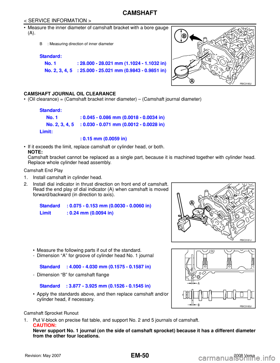
• Measure the inner diameter of camshaft bracket with a bore gauge
(A).
CAMSHAFT JOURNAL OIL CLEARANCE
• (Oil clearance) = (Camshaft bracket inner diameter) – (Camshaft journal diameter)
• If it exceeds the limit, replace camshaft or cylinder head, or both.
NOTE:
Camshaft bracket cannot be replaced as a single part, because it is machined together with cylinder head.
Replace whole cylinder head assembly.
Camshaft End Play
1. Install camshaft in cylinder head.
2. Install dial indicator in thrust direction on front end of camshaft.
Read the end play of dial indicator (A) when camshaft is moved
forward/backward (in direction to axis).
• Measure the following parts if out of the standard.
- Dimension “A” for groove of cylinder head No. 1 journal
- Dimension “B” for camshaft flange
• Apply the standards above, and then replace camshaft and/or
cylinder head, if necessary.
Camshaft Sprocket Runout
1. Put V-block on precise flat table, and support No. 2 and 5 journals of camshaft.
CAUTION:
Never support No. 1 journal (on the side of camshaft sprocket) because it has a different diameter
from the other four locations.
B : Measuring direction of inner diameter
Standard:
No. 1 : 28.000 - 28.021 mm (1.1024 - 1.1032 in)
No. 2, 3, 4, 5 : 25.000 - 25.021 mm (0.9843 - 0.9851 in)
PBIC3180J
Standard:
No. 1 : 0.045 - 0.086 mm (0.0018 - 0.0034 in)
No. 2, 3, 4, 5 : 0.030 - 0.071 mm (0.0012 - 0.0028 in)
Limit:
: 0.15 mm (0.0059 in)
Standard : 0.075 - 0.153 mm (0.0030 - 0.0060 in)
Limit : 0.24 mm (0.0094 in)
PBIC3181J
Standard : 4.000 - 4.030 mm (0.1575 - 0.1587 in)
Standard : 3.877 - 3.925 mm (0.1526 - 0.1545 in)
PBIC3183J
Page 1776 of 2771
CYLINDER BLOCK
EM-99
< SERVICE INFORMATION >
C
D
E
F
G
H
I
J
K
L
MA
EM
N
P O
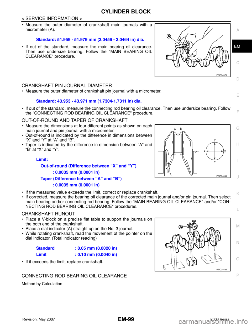
• Measure the outer diameter of crankshaft main journals with a
micrometer (A).
• If out of the standard, measure the main bearing oil clearance.
Then use undersize bearing. Follow the "MAIN BEARING OIL
CLEARANCE" procedure.
CRANKSHAFT PIN JOURNAL DIAMETER
• Measure the outer diameter of crankshaft pin journal with a micrometer.
• If out of the standard, measure the connecting rod bearing oil clearance. Then use undersize bearing. Follow
the "CONNECTING ROD BEARING OIL CLEARANCE" procedure.
OUT-OF-ROUND AND TAPER OF CRANKSHAFT
• Measure the dimensions at four different points as shown on each
main journal and pin journal with a micrometer.
• Out-of-round is indicated by the difference in dimensions between
“X” and “Y” at “A” and “B”.
• Taper is indicated by the difference in dimension between “A” and
“B” at “X” and “Y”.
• If the measured value exceeds the limit, correct or replace crankshaft.
• If corrected, measure the bearing oil clearance of the corrected main journal and/or pin journal. Then select
main bearing and/or connecting rod bearing. Follow the "MAIN BEARING OIL CLEARANCE" and/or "CON-
NECTING ROD BEARING OIL CLEARANCE" procedures.
CRANKSHAFT RUNOUT
• Place a V-block on a precise flat table to support the journals on
the both end of the crankshaft.
• Place a dial indicator (A) straight up on the No. 3 journal.
• While rotating crankshaft, read the movement of the pointer on the
dial indicator. (Total indicator reading)
• If it exceeds the limit, replace crankshaft.
CONNECTING ROD BEARING OIL CLEARANCE
Method by Calculation
Standard: 51.959 - 51.979 mm (2.0456 - 2.0464 in) dia.
PBIC3457J
Standard: 43.953 - 43.971 mm (1.7304-1.7311 in) dia.
Limit:
Out-of-round (Difference between “X” and “Y”)
: 0.0035 mm (0.0001 in)
Taper (Difference between “A” and “B”)
: 0.0035 mm (0.0001 in)
PBIC3459J
Standard : 0.05 mm (0.0020 in)
Limit : 0.10 mm (0.0040 in)
PBIC3458J
Page 1840 of 2771
FSU-6
< SERVICE INFORMATION >
FRONT SUSPENSION ASSEMBLY
FRONT SUSPENSION ASSEMBLY
On-Vehicle Inspection and ServiceINFOID:0000000001703721
Make sure the mounting conditions (looseness, back lash) of each component and component conditions
(wear, damage) are normal.
INSPECTION OF LOWER BALL JOINT END PLAY
1. Set front wheels in a straight-ahead position. Do not depress brake pedal.
2. Place an iron bar or similar tool between transverse link and steering knuckle.
3. Measure axial end play by prying it up and down.
CAUTION:
Be careful not to damage ball joint boot. Do not damage the installation position by applying
excessive force.
STRUT INSPECTION
Check for oil leakage, damage and replace as necessary.
Wheel Alignment InspectionINFOID:0000000001703722
PRELIMINARY INSPECTION
WARNING:
Always adjust the alignment with the vehicle on a flat surface.
NOTE:
If alignment is out of specification, inspect and replace any damaged or worn rear suspension parts before
making any adjustments.
1. Check and adjust the wheel alignment with the vehicle under unladen conditions. “Unladen conditions”
means that the fuel, coolant, and lubricant are full; and that the spare tire, jack, hand tools and mats are in
their designated positions.
2. Check the tires for incorrect air pressure and excessive wear.
3. Check the wheels for run out and damage. Refer to WT-5, "
Inspection" .
4. Check the wheel bearing axial end play. Refer to FA X - 5 , "
On-Vehicle Inspection and Service" .
5. Check the shock absorbers for leaks or damage.
6. Check each mounting point of the suspension components for any excessive looseness or damage.
7. Check each link, arm, and the suspension member for any damage.
8. Check the vehicle height. Refer to FSU-17, "
Wheelarch Height (Unladen*)" .
GENERAL INFORMATION AND RECOMMENDATIONS
1. A Four-Wheel Thrust Alignment should be performed.
• This type of alignment is recommended for any NISSAN vehicle.
• The four-wheel “thrust” process helps ensure that the vehicle is properly aligned and the steering wheel
is centered.
• The alignment machine itself should be capable of accepting any NISSAN vehicle.
• The alignment machine should be checked to ensure that it is level.
2. Make sure the alignment machine is properly calibrated.
• Your alignment machine should be regularly calibrated in order to give correct information.
• Check with the manufacturer of your specific alignment machine for their recommended Service/Cali-
bration Schedule.
THE ALIGNMENT PROCESS
IMPORTANT: Use only the alignment specifications listed in this Service Manual. Refer to FSU-16, "Wheel
Alignment (Unladen*)" .
1. When displaying the alignment settings, many alignment machines use “indicators”: (Green/red, plus or
minus, Go/No Go). Do NOT use these indicators.
• The alignment specifications programmed into your alignment machine that operate these indicators
may not be correct.Axial end play : 0 mm (0 in)
Page 1917 of 2771
GW-16
< SERVICE INFORMATION >
REAR WINDOW GLASS AND MOLDING
Sedan
REMOVAL
1. If equipped, remove the rear wiper arm and motor. Refer to WW-31, "Removal and Installation" .
2. Remove the connectors and grounds for the rear window defogger.
• Remove glass using piano wire or power cutting tool and an inflat-
able pump bag.
• If the rear window glass is to be reused, mark the body and the
glass with mating marks.
WARNING:
When cutting the glass from the vehicle, always wear safety
glasses and heavy gloves to help prevent glass splinters from
entering your eyes or cutting your hands.
CAUTION:
• When a windshield glass is to be reused, do not use a cutting
knife or power cutting tool.
• Be careful not to scratch the glass when removing.
• Do not set or stand the glass on its edge. Small chips may develop into cracks.
INSTALLATION
LIIA2913E
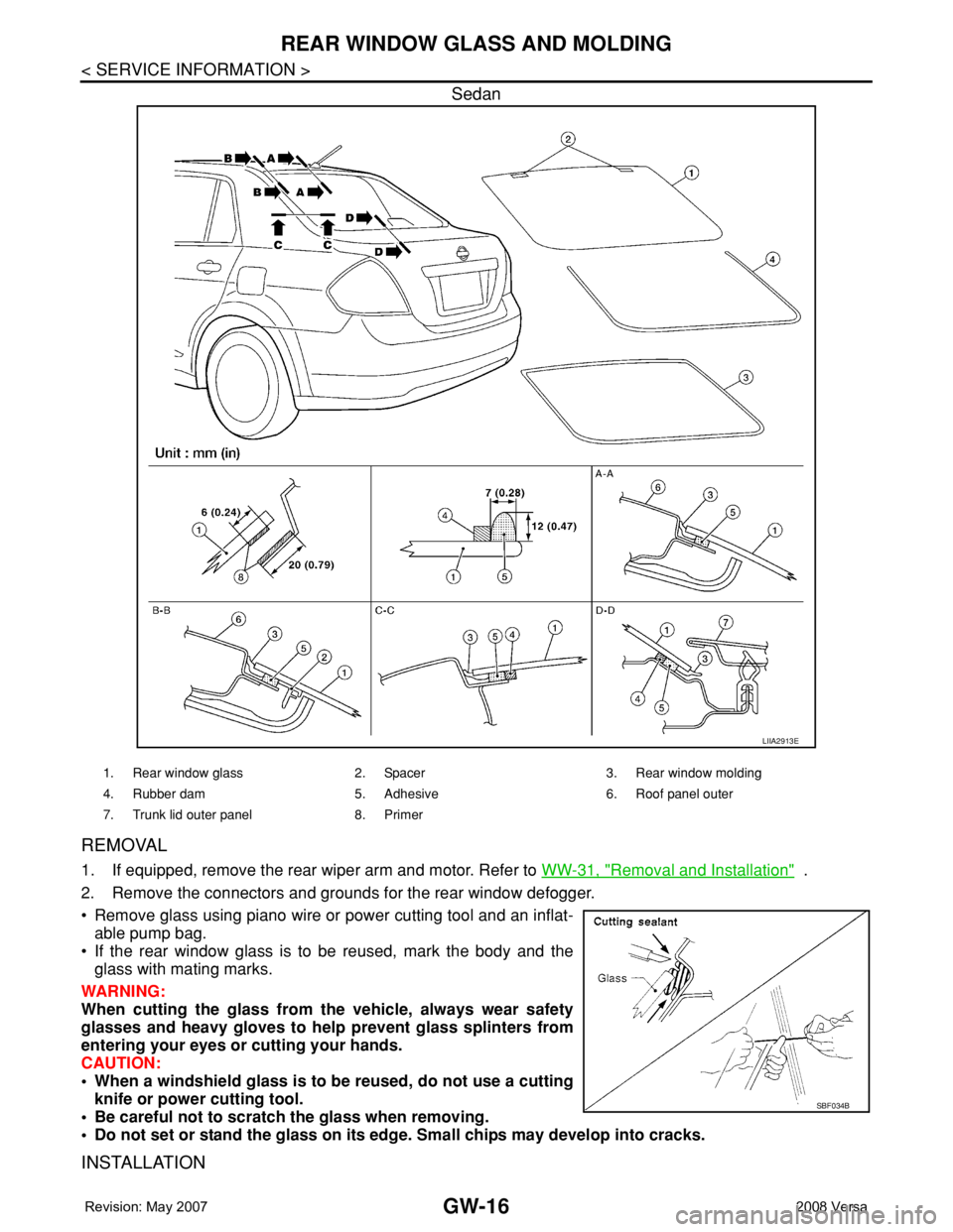
1. Rear window glass 2. Spacer 3. Rear window molding
4. Rubber dam 5. Adhesive 6. Roof panel outer
7. Trunk lid outer panel 8. Primer
SBF034B
Page 2567 of 2771
RSU-8
< SERVICE INFORMATION >
SHOCK ABSORBER
SHOCK ABSORBER
Removal and InstallationINFOID:0000000001703739
REMOVAL
1. Remove rear tires from vehicle using power tool.
2. Remove wheel sensor from wheel hub and bearing assembly and rear suspension beam. Refer to BRC-
32 .
CAUTION:
Do not pull on wheel sensor harness.
3. Remove shock absorber mask from trunk side finisher using a flat-bladed screwdriver. Refer to EI-51
.
CAUTION:
Wrap the tip of a screwdriver with cloth to avoid damaging components.
4. Set jack under rear suspension beam.
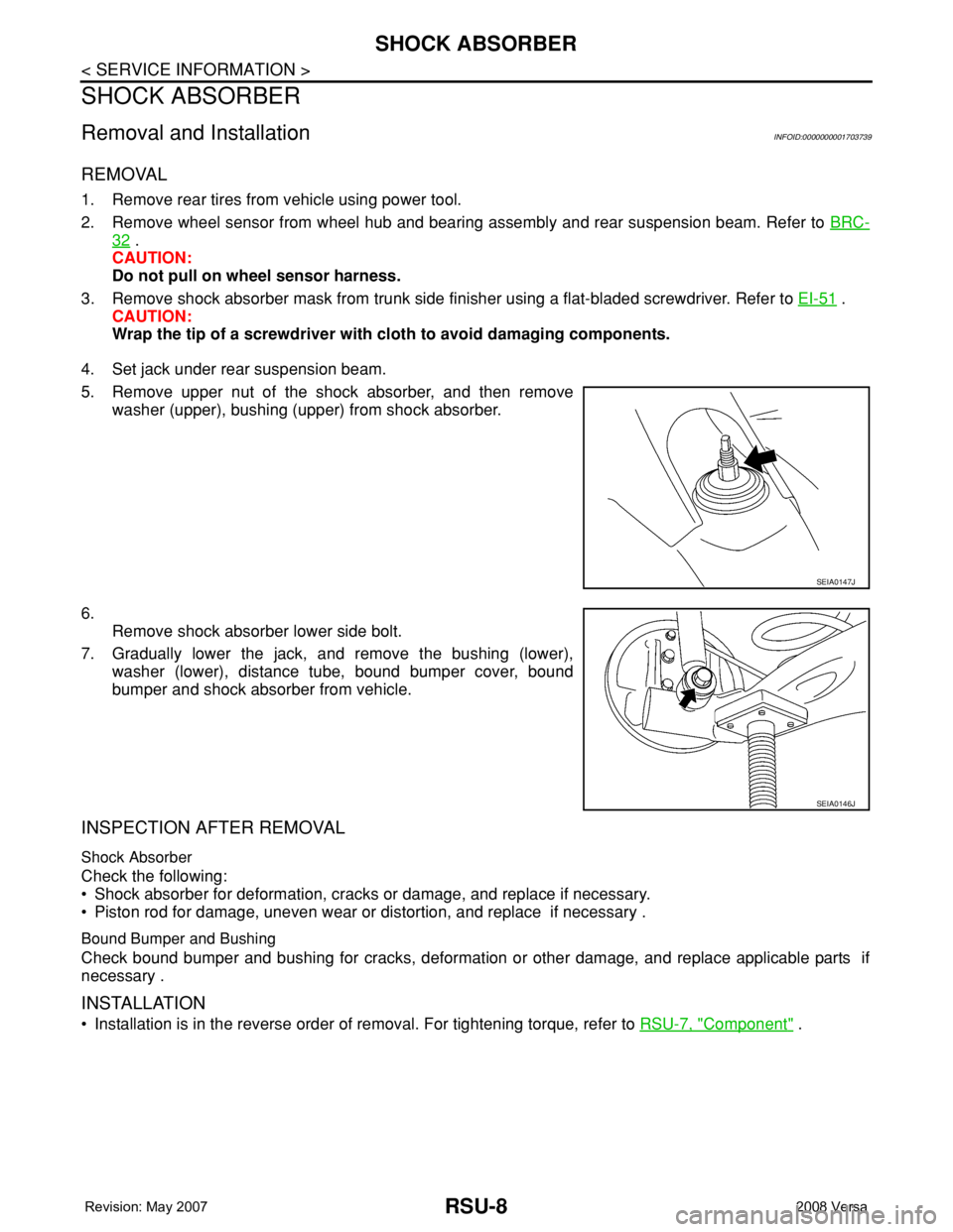
5. Remove upper nut of the shock absorber, and then remove
washer (upper), bushing (upper) from shock absorber.
6.
Remove shock absorber lower side bolt.
7. Gradually lower the jack, and remove the bushing (lower),
washer (lower), distance tube, bound bumper cover, bound
bumper and shock absorber from vehicle.
INSPECTION AFTER REMOVAL
Shock Absorber
Check the following:
• Shock absorber for deformation, cracks or damage, and replace if necessary.
• Piston rod for damage, uneven wear or distortion, and replace if necessary .
Bound Bumper and Bushing
Check bound bumper and bushing for cracks, deformation or other damage, and replace applicable parts if
necessary .
INSTALLATION
• Installation is in the reverse order of removal. For tightening torque, refer to RSU-7, "Component" .
SEIA0147J
SEIA0146J
Page 2713 of 2771
ROAD WHEEL
WT-5
< SERVICE INFORMATION >
C
D
F
G
H
I
J
K
L
MA
B
WT
N
O
P
ROAD WHEEL
InspectionINFOID:0000000001703748
ALUMINUM WHEEL
1. Check tires for wear and improper inflation.
2. Check wheels for deformation, cracks and other damage. If deformed, remove wheel and check wheel
runout.
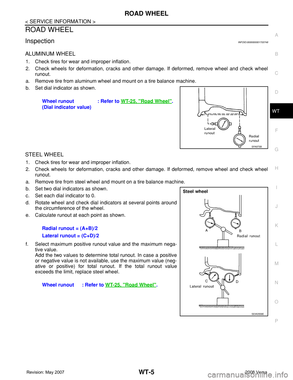
a. Remove tire from aluminum wheel and mount on a tire balance machine.
b. Set dial indicator as shown.
STEEL WHEEL
1. Check tires for wear and improper inflation.
2. Check wheels for deformation, cracks and other damage. If deformed, remove wheel and check wheel
runout.
a. Remove tire from steel wheel and mount on a tire balance machine.
b. Set two dial indicators as shown.
c. Set each dial indicator to 0.
d. Rotate wheel and check dial indicators at several points around
the circumference of the wheel.
e. Calculate runout at each point as shown.
f. Select maximum positive runout value and the maximum nega-
tive value.
Add the two values to determine total runout. In case a positive
or negative value is not available, use the maximum value (neg-
ative or positive) for total runout. If the total runout value
exceeds the limit, replace steel wheel.Wheel runout
(Dial indicator value): Refer to WT-25, "
Road Wheel".
SFA975B
Radial runout = (A+B)/2
Lateral runout = (C+D)/2
Wheel runout : Refer to WT-25, "
Road Wheel".
SEIA0558E