run flat NISSAN LATIO 2008 Service Repair Manual
[x] Cancel search | Manufacturer: NISSAN, Model Year: 2008, Model line: LATIO, Model: NISSAN LATIO 2008Pages: 2771, PDF Size: 60.61 MB
Page 90 of 2771
AT-78
< SERVICE INFORMATION >
TROUBLE DIAGNOSIS
Diagnosis Procedure without CONSULT-III
INFOID:0000000001703194
TCM SELF-DIAGNOSTIC PROCEDURE
Description
If a malfunction occurs in electrical system, turning ignition switch ON will illuminate OD OFF indicator lamp for
2 seconds. To detect a malfunction, entering a self-diagnosis start signal retrieves information on malfunctions
from memory and indicates malfunction by blinking OD OFF indicator lamp.
Diagnostic Procedure
1.CHECK OD OFF INDICATOR LAMP
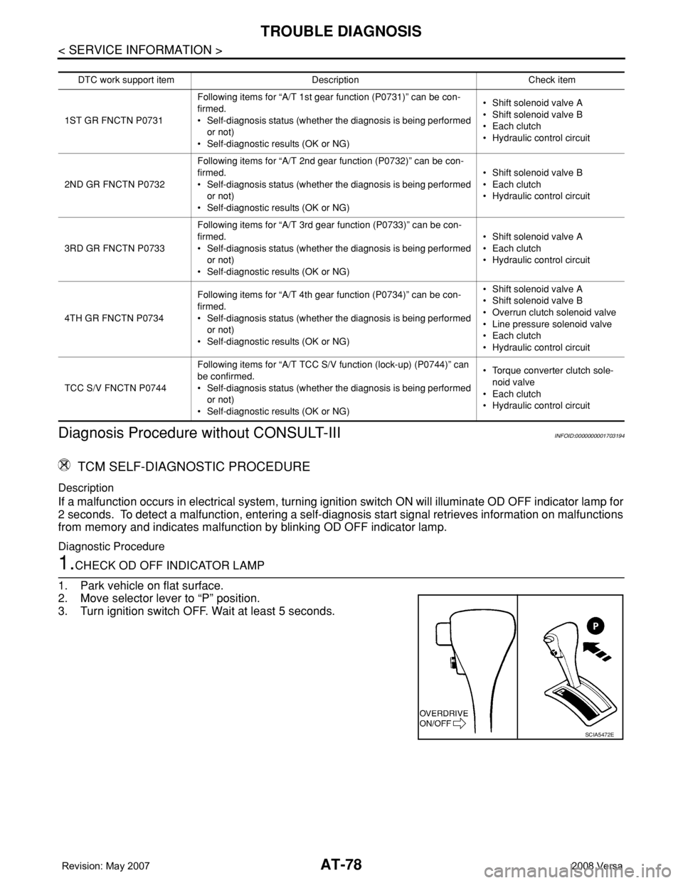
1. Park vehicle on flat surface.
2. Move selector lever to “P” position.
3. Turn ignition switch OFF. Wait at least 5 seconds.
DTC work support itemDescription Check item
1ST GR FNCTN P0731Following items for “A/T 1st gear function (P0731)” can be con-
firmed.
• Self-diagnosis status (whether the diagnosis is being performed
or not)
• Self-diagnostic results (OK or NG)• Shift solenoid valve A
• Shift solenoid valve B
• Each clutch
•Hydraulic control circuit
2ND GR FNCTN P0732Following items for “A/T 2nd gear function (P0732)” can be con-
firmed.
• Self-diagnosis status (whether the diagnosis is being performed
or not)
• Self-diagnostic results (OK or NG)• Shift solenoid valve B
• Each clutch
•Hydraulic control circuit
3RD GR FNCTN P0733Following items for “A/T 3rd gear function (P0733)” can be con-
firmed.
• Self-diagnosis status (whether the diagnosis is being performed
or not)
• Self-diagnostic results (OK or NG)• Shift solenoid valve A
• Each clutch
•Hydraulic control circuit
4TH GR FNCTN P0734Following items for “A/T 4th gear function (P0734)” can be con-
firmed.
• Self-diagnosis status (whether the diagnosis is being performed
or not)
• Self-diagnostic results (OK or NG)• Shift solenoid valve A
• Shift solenoid valve B
• Overrun clutch solenoid valve
• Line pressure solenoid valve
• Each clutch
•Hydraulic control circuit
TCC S/V FNCTN P0744Following items for “A/T TCC S/V function (lock-up) (P0744)” can
be confirmed.
• Self-diagnosis status (whether the diagnosis is being performed
or not)
• Self-diagnostic results (OK or NG)• Torque converter clutch sole-
noid valve
• Each clutch
•Hydraulic control circuit
SCIA5472E
Page 286 of 2771
AT-274
< SERVICE INFORMATION >
REPAIR FOR COMPONENT PARTS
DISASSEMBLY
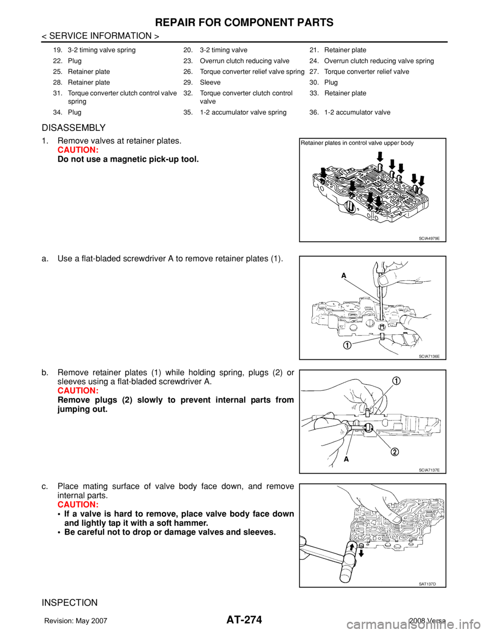
1. Remove valves at retainer plates.
CAUTION:
Do not use a magnetic pick-up tool.
a. Use a flat-bladed screwdriver A to remove retainer plates (1).
b. Remove retainer plates (1) while holding spring, plugs (2) or
sleeves using a flat-bladed screwdriver A.
CAUTION:
Remove plugs (2) slowly to prevent internal parts from
jumping out.
c. Place mating surface of valve body face down, and remove
internal parts.
CAUTION:
• If a valve is hard to remove, place valve body face down
and lightly tap it with a soft hammer.
• Be careful not to drop or damage valves and sleeves.
INSPECTION
19. 3-2 timing valve spring 20. 3-2 timing valve 21. Retainer plate
22. Plug 23. Overrun clutch reducing valve 24. Overrun clutch reducing valve spring
25. Retainer plate 26. Torque converter relief valve spring 27. Torque converter relief valve
28. Retainer plate 29. Sleeve 30. Plug
31. Torque converter clutch control valve
spring32. Torque converter clutch control
valve33. Retainer plate
34. Plug 35. 1-2 accumulator valve spring 36. 1-2 accumulator valve
SCIA4979E
SCIA7136E
SCIA7137E
SAT137D
Page 288 of 2771
AT-276
< SERVICE INFORMATION >
REPAIR FOR COMPONENT PARTS
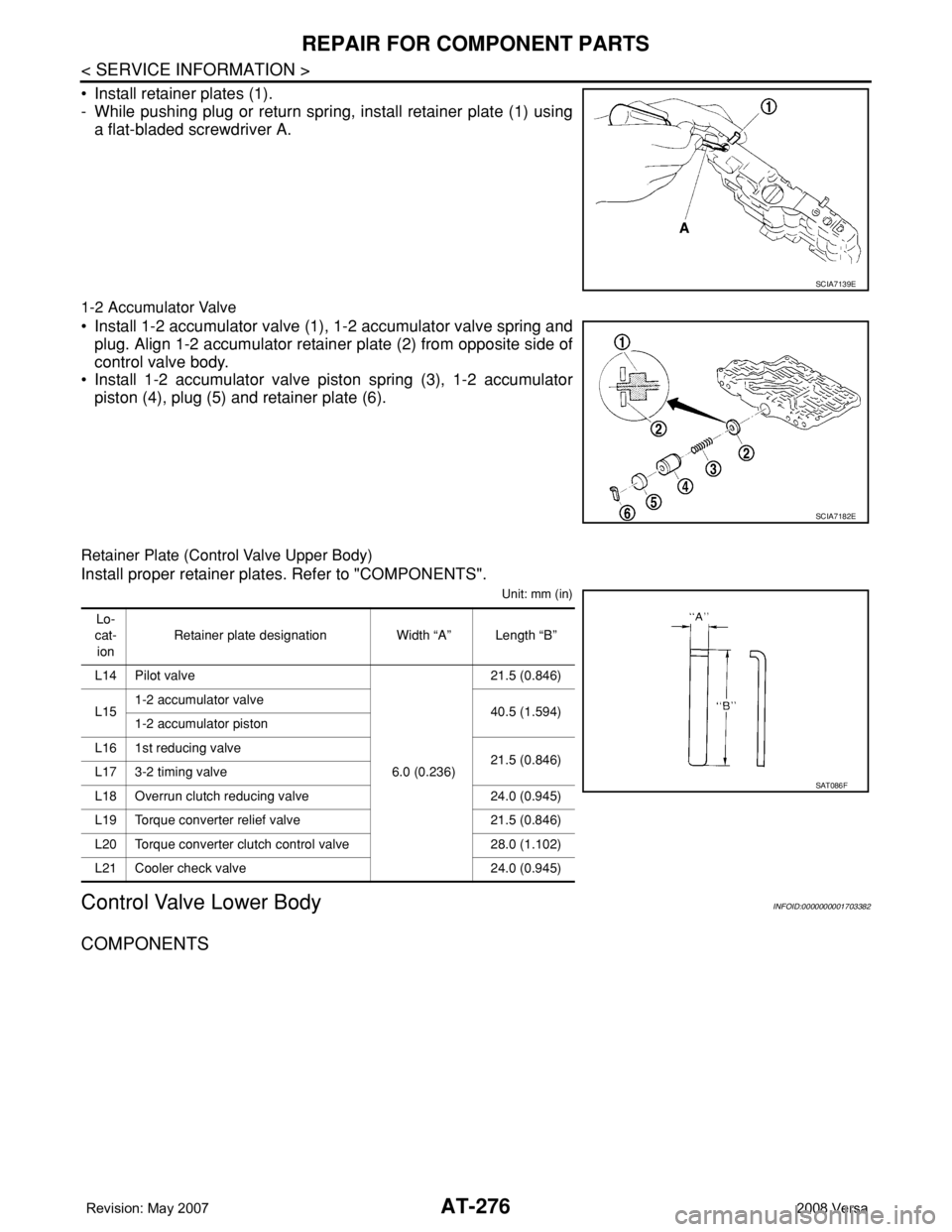
• Install retainer plates (1).
- While pushing plug or return spring, install retainer plate (1) using
a flat-bladed screwdriver A.
1-2 Accumulator Valve
• Install 1-2 accumulator valve (1), 1-2 accumulator valve spring and
plug. Align 1-2 accumulator retainer plate (2) from opposite side of
control valve body.
• Install 1-2 accumulator valve piston spring (3), 1-2 accumulator
piston (4), plug (5) and retainer plate (6).
Retainer Plate (Control Valve Upper Body)
Install proper retainer plates. Refer to "COMPONENTS".
Unit: mm (in)
Control Valve Lower BodyINFOID:0000000001703382
COMPONENTS
SCIA7139E
SCIA7182E
Lo-
cat-
ionRetainer plate designation Width “A” Length “B”
L14 Pilot valve
6.0 (0.236)21.5 (0.846)
L151-2 accumulator valve
40.5 (1.594)
1-2 accumulator piston
L16 1st reducing valve
21.5 (0.846)
L17 3-2 timing valve
L18 Overrun clutch reducing valve 24.0 (0.945)
L19 Torque converter relief valve 21.5 (0.846)
L20 Torque converter clutch control valve 28.0 (1.102)
L21 Cooler check valve 24.0 (0.945)
SAT086F
Page 300 of 2771
AT-288
< SERVICE INFORMATION >
REPAIR FOR COMPONENT PARTS
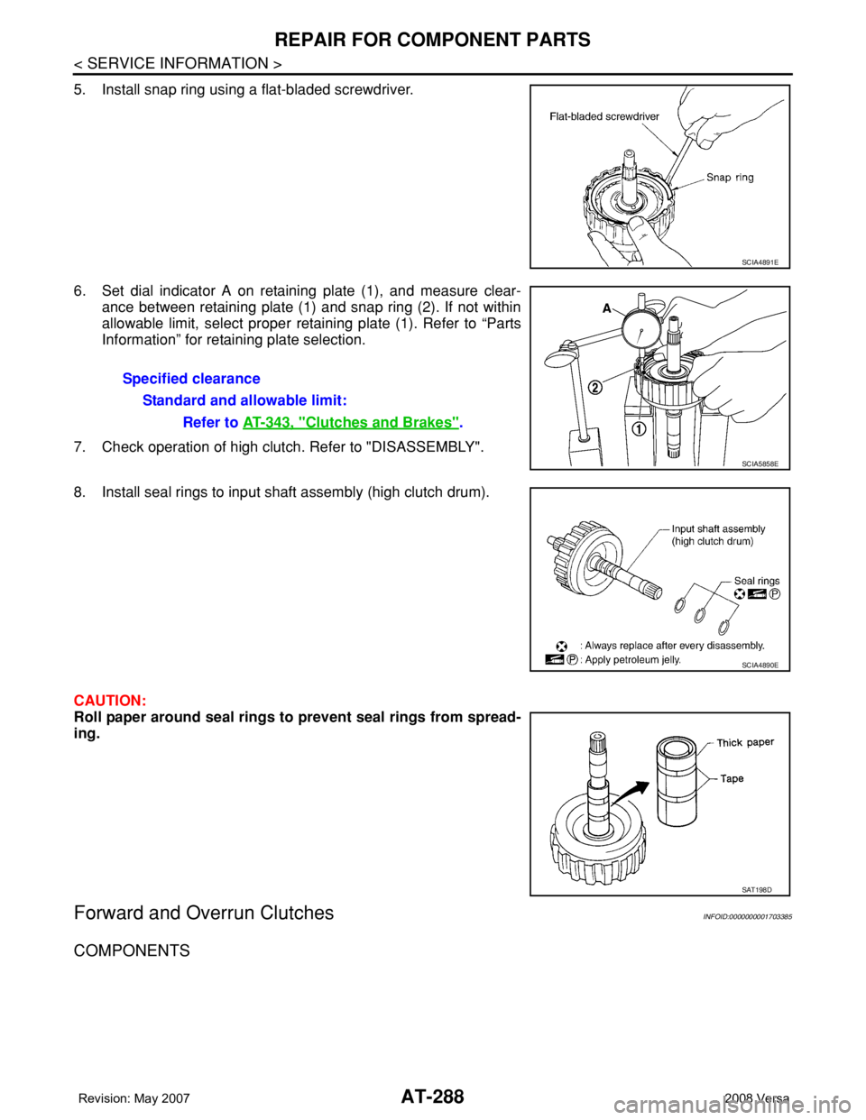
5. Install snap ring using a flat-bladed screwdriver.
6. Set dial indicator A on retaining plate (1), and measure clear-
ance between retaining plate (1) and snap ring (2). If not within
allowable limit, select proper retaining plate (1). Refer to “Parts
Information” for retaining plate selection.
7. Check operation of high clutch. Refer to "DISASSEMBLY".
8. Install seal rings to input shaft assembly (high clutch drum).
CAUTION:
Roll paper around seal rings to prevent seal rings from spread-
ing.
Forward and Overrun ClutchesINFOID:0000000001703385
COMPONENTS
SCIA4891E
Specified clearance
Standard and allowable limit:
Refer to AT-343, "
Clutches and Brakes".
SCIA5858E
SCIA4890E
SAT198D
Page 302 of 2771
AT-290
< SERVICE INFORMATION >
REPAIR FOR COMPONENT PARTS
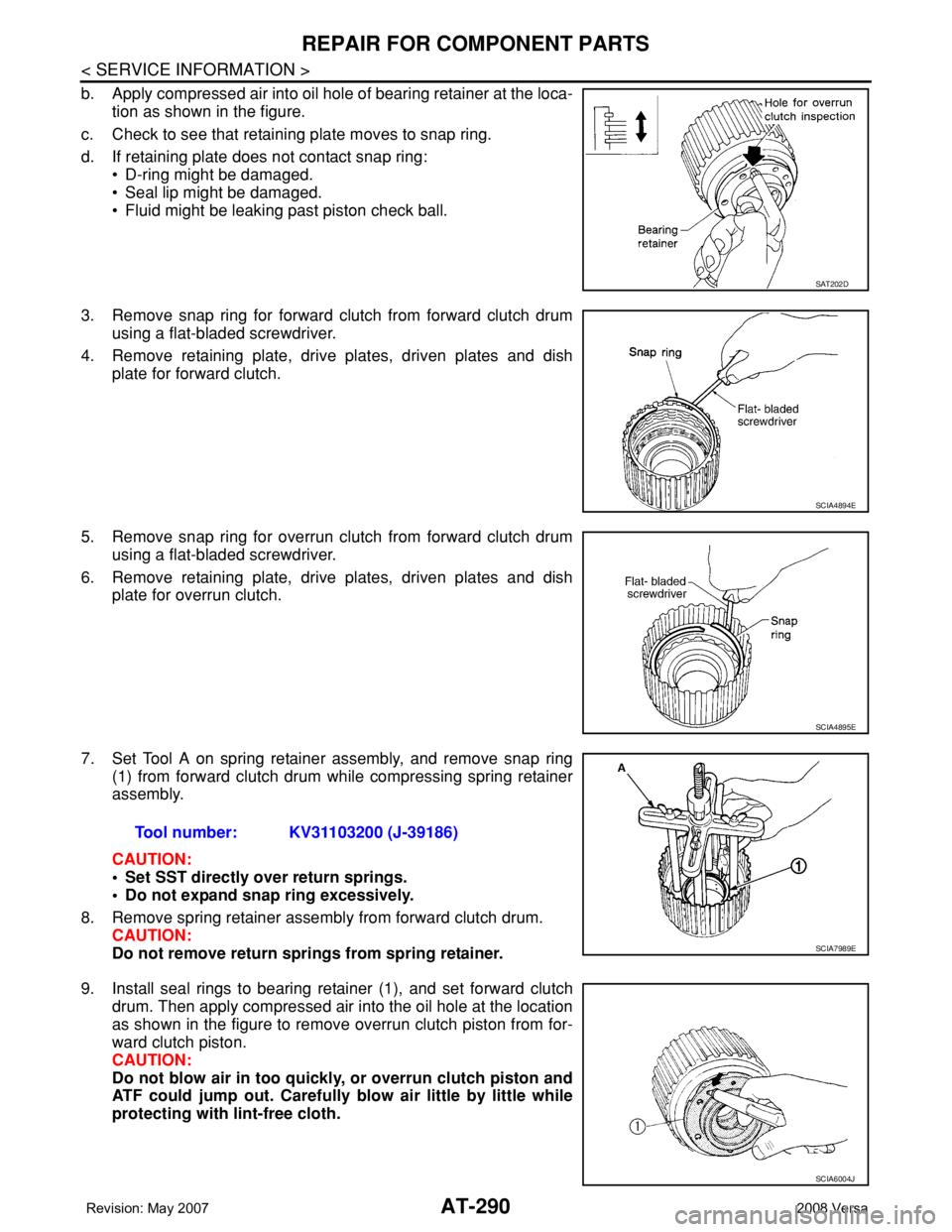
b. Apply compressed air into oil hole of bearing retainer at the loca-
tion as shown in the figure.
c. Check to see that retaining plate moves to snap ring.
d. If retaining plate does not contact snap ring:
• D-ring might be damaged.
• Seal lip might be damaged.
• Fluid might be leaking past piston check ball.
3. Remove snap ring for forward clutch from forward clutch drum
using a flat-bladed screwdriver.
4. Remove retaining plate, drive plates, driven plates and dish
plate for forward clutch.
5. Remove snap ring for overrun clutch from forward clutch drum
using a flat-bladed screwdriver.
6. Remove retaining plate, drive plates, driven plates and dish
plate for overrun clutch.
7. Set Tool A on spring retainer assembly, and remove snap ring
(1) from forward clutch drum while compressing spring retainer
assembly.
CAUTION:
• Set SST directly over return springs.
• Do not expand snap ring excessively.
8. Remove spring retainer assembly from forward clutch drum.
CAUTION:
Do not remove return springs from spring retainer.
9. Install seal rings to bearing retainer (1), and set forward clutch
drum. Then apply compressed air into the oil hole at the location
as shown in the figure to remove overrun clutch piston from for-
ward clutch piston.
CAUTION:
Do not blow air in too quickly, or overrun clutch piston and
ATF could jump out. Carefully blow air little by little while
protecting with lint-free cloth.
SAT202D
SCIA4894E
SCIA4895E
Tool number: KV31103200 (J-39186)
SCIA7989E
SCIA6004J
Page 306 of 2771
AT-294
< SERVICE INFORMATION >
REPAIR FOR COMPONENT PARTS
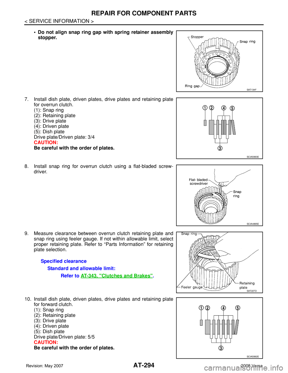
• Do not align snap ring gap with spring retainer assembly
stopper.
7. Install dish plate, driven plates, drive plates and retaining plate
for overrun clutch.
(1): Snap ring
(2): Retaining plate
(3): Drive plate
(4): Driven plate
(5): Dish plate
Drive plate/Driven plate: 3/4
CAUTION:
Be careful with the order of plates.
8. Install snap ring for overrun clutch using a flat-bladed screw-
driver.
9. Measure clearance between overrun clutch retaining plate and
snap ring using feeler gauge. If not within allowable limit, select
proper retaining plate. Refer to “Parts Information” for retaining
plate selection.
10. Install dish plate, driven plates, drive plates and retaining plate
for forward clutch.
(1): Snap ring
(2): Retaining plate
(3): Drive plate
(4): Driven plate
(5): Dish plate
Drive plate/Driven plate: 5/5
CAUTION:
Be careful with the order of plates.
SAT134F
SCIA5993E
SCIA4895E
Specified clearance
Standard and allowable limit:
Refer to AT-343, "
Clutches and Brakes".
SAT227D
SCIA5992E
Page 307 of 2771
REPAIR FOR COMPONENT PARTS
AT-295
< SERVICE INFORMATION >
D
E
F
G
H
I
J
K
L
MA
B
AT
N
O
P
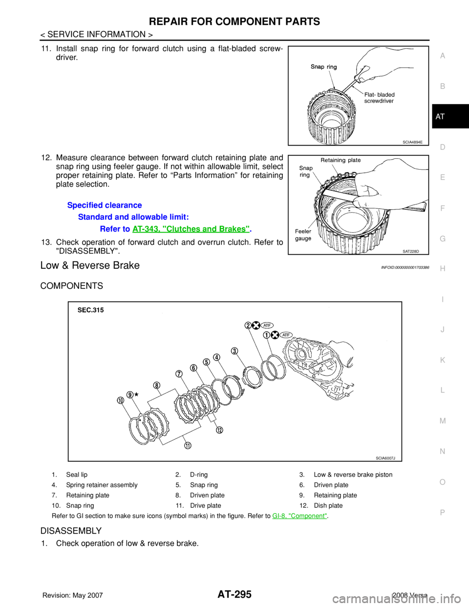
11. Install snap ring for forward clutch using a flat-bladed screw-
driver.
12. Measure clearance between forward clutch retaining plate and
snap ring using feeler gauge. If not within allowable limit, select
proper retaining plate. Refer to “Parts Information” for retaining
plate selection.
13. Check operation of forward clutch and overrun clutch. Refer to
"DISASSEMBLY".
Low & Reverse BrakeINFOID:0000000001703386
COMPONENTS
DISASSEMBLY
1. Check operation of low & reverse brake.
SCIA4894E
Specified clearance
Standard and allowable limit:
Refer to AT-343, "
Clutches and Brakes".
SAT228D
1. Seal lip 2. D-ring 3. Low & reverse brake piston
4. Spring retainer assembly 5. Snap ring 6. Driven plate
7. Retaining plate 8. Driven plate 9. Retaining plate
10. Snap ring 11. Drive plate 12. Dish plate
Refer to GI section to make sure icons (symbol marks) in the figure. Refer to GI-8, "
Component".
SCIA6007J
Page 759 of 2771
BR-28
< SERVICE INFORMATION >
FRONT DISC BRAKE
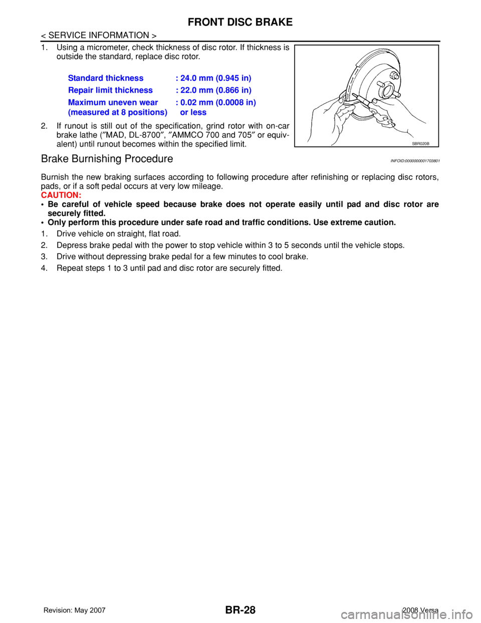
1. Using a micrometer, check thickness of disc rotor. If thickness is
outside the standard, replace disc rotor.
2. If runout is still out of the specification, grind rotor with on-car
brake lathe (″MAD, DL-8700″, ″AMMCO 700 and 705″ or equiv-
alent) until runout becomes within the specified limit.
Brake Burnishing ProcedureINFOID:0000000001703801
Burnish the new braking surfaces according to following procedure after refinishing or replacing disc rotors,
pads, or if a soft pedal occurs at very low mileage.
CAUTION:
• Be careful of vehicle speed because brake does not operate easily until pad and disc rotor are
securely fitted.
• Only perform this procedure under safe road and traffic conditions. Use extreme caution.
1. Drive vehicle on straight, flat road.
2. Depress brake pedal with the power to stop vehicle within 3 to 5 seconds until the vehicle stops.
3. Drive without depressing brake pedal for a few minutes to cool brake.
4. Repeat steps 1 to 3 until pad and disc rotor are securely fitted.Standard thickness : 24.0 mm (0.945 in)
Repair limit thickness : 22.0 mm (0.866 in)
Maximum uneven wear
(measured at 8 positions): 0.02 mm (0.0008 in)
or less
SBR020B
Page 1131 of 2771
ON BOARD DIAGNOSTIC (OBD) SYSTEM
EC-57
< SERVICE INFORMATION >
C
D
E
F
G
H
I
J
K
L
MA
EC
N
P O
• Sea level
• Flat road
• Ambient air temperature: 20 - 30°C (68 - 86°F)
• Diagnosis is performed as quickly as possible under normal conditions.
Under different conditions [For example: ambient air temperature other than 20 - 30°C (68 - 86°F)], diagno-
sis may also be performed.
Pattern 1:
•The engine is started at the engine coolant temperature of −10 to 35°C (14 to 95°F)
(where the voltage between the ECM terminal 38 and ground is 3.0 - 4.3V).
•The engine must be operated at idle speed until the engine coolant temperature is greater than 70°C
(158°F) (where the voltage between the ECM terminal 38 and ground is lower than 1.4V).
•The engine is started at the fuel tank temperature of warmer than 0°C (32°F) (where the voltage
between the ECM terminal 43 and ground is less than 4.1V).
Pattern 2:
• When steady-state driving is performed again even after it is interrupted, each diagnosis can be conducted.
In this case, the time required for diagnosis may be extended.
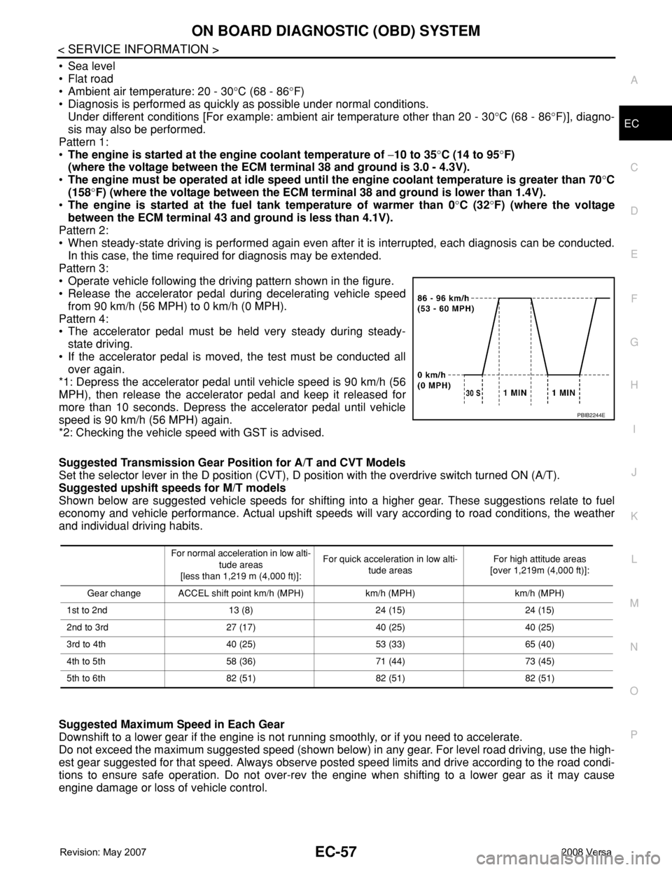
Pattern 3:
• Operate vehicle following the driving pattern shown in the figure.
• Release the accelerator pedal during decelerating vehicle speed
from 90 km/h (56 MPH) to 0 km/h (0 MPH).
Pattern 4:
• The accelerator pedal must be held very steady during steady-
state driving.
• If the accelerator pedal is moved, the test must be conducted all
over again.
*1: Depress the accelerator pedal until vehicle speed is 90 km/h (56
MPH), then release the accelerator pedal and keep it released for
more than 10 seconds. Depress the accelerator pedal until vehicle
speed is 90 km/h (56 MPH) again.
*2: Checking the vehicle speed with GST is advised.
Suggested Transmission Gear Position for A/T and CVT Models
Set the selector lever in the D position (CVT), D position with the overdrive switch turned ON (A/T).
Suggested upshift speeds for M/T models
Shown below are suggested vehicle speeds for shifting into a higher gear. These suggestions relate to fuel
economy and vehicle performance. Actual upshift speeds will vary according to road conditions, the weather
and individual driving habits.
Suggested Maximum Speed in Each Gear
Downshift to a lower gear if the engine is not running smoothly, or if you need to accelerate.
Do not exceed the maximum suggested speed (shown below) in any gear. For level road driving, use the high-
est gear suggested for that speed. Always observe posted speed limits and drive according to the road condi-
tions to ensure safe operation. Do not over-rev the engine when shifting to a lower gear as it may cause
engine damage or loss of vehicle control.
PBIB2244E
For normal acceleration in low alti-
tude areas
[less than 1,219 m (4,000 ft)]:For quick acceleration in low alti-
tude areasFor high attitude areas
[over 1,219m (4,000 ft)]:
Gear change ACCEL shift point km/h (MPH) km/h (MPH) km/h (MPH)
1st to 2nd 13 (8) 24 (15) 24 (15)
2nd to 3rd 27 (17) 40 (25) 40 (25)
3rd to 4th 40 (25) 53 (33) 65 (40)
4th to 5th 58 (36) 71 (44) 73 (45)
5th to 6th 82 (51) 82 (51) 82 (51)
Page 1726 of 2771
CAMSHAFT
EM-49
< SERVICE INFORMATION >
C
D
E
F
G
H
I
J
K
L
MA
EM
N
P O
13. Remove valve lifters.
NOTE:
Identify installed positions, and store them without mixing them up.
INSPECTION AFTER REMOVAL
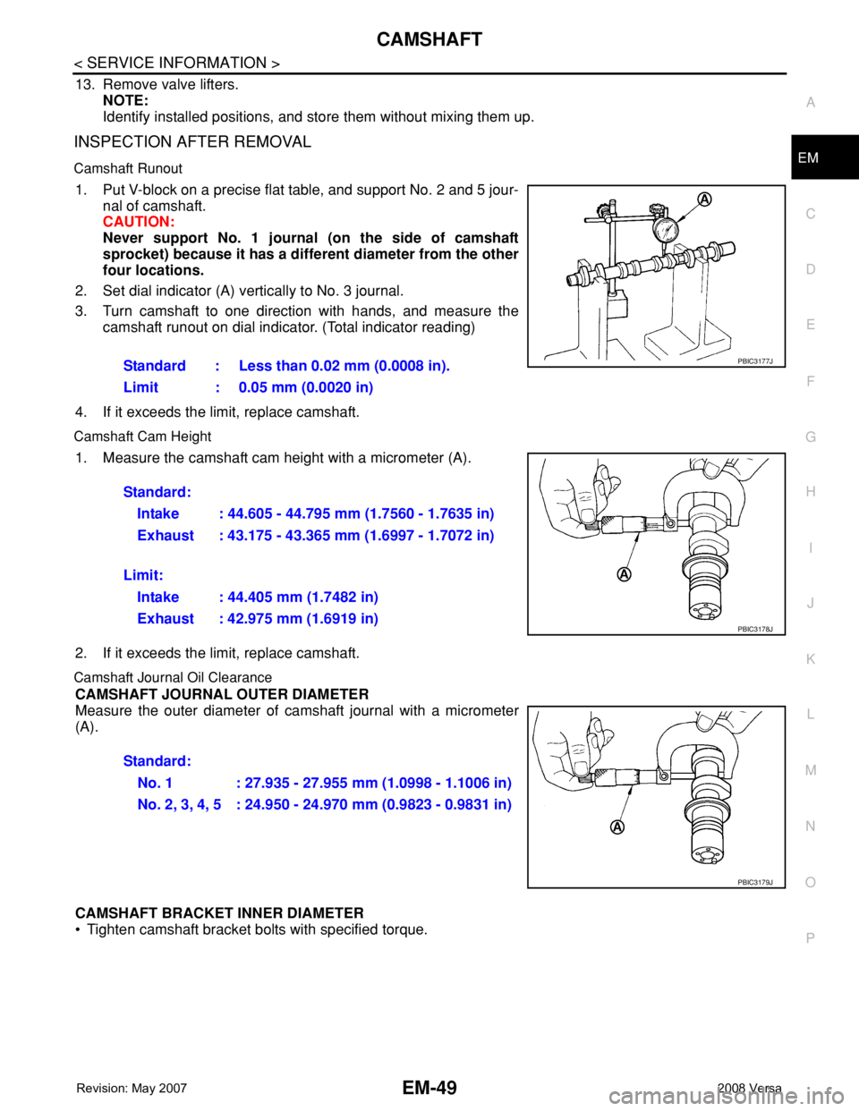
Camshaft Runout
1. Put V-block on a precise flat table, and support No. 2 and 5 jour-
nal of camshaft.
CAUTION:
Never support No. 1 journal (on the side of camshaft
sprocket) because it has a different diameter from the other
four locations.
2. Set dial indicator (A) vertically to No. 3 journal.
3. Turn camshaft to one direction with hands, and measure the
camshaft runout on dial indicator. (Total indicator reading)
4. If it exceeds the limit, replace camshaft.
Camshaft Cam Height
1. Measure the camshaft cam height with a micrometer (A).
2. If it exceeds the limit, replace camshaft.
Camshaft Journal Oil Clearance
CAMSHAFT JOURNAL OUTER DIAMETER
Measure the outer diameter of camshaft journal with a micrometer
(A).
CAMSHAFT BRACKET INNER DIAMETER
• Tighten camshaft bracket bolts with specified torque. Standard : Less than 0.02 mm (0.0008 in).
Limit : 0.05 mm (0.0020 in)
PBIC3177J
Standard:
Intake : 44.605 - 44.795 mm (1.7560 - 1.7635 in)
Exhaust : 43.175 - 43.365 mm (1.6997 - 1.7072 in)
Limit:
Intake : 44.405 mm (1.7482 in)
Exhaust : 42.975 mm (1.6919 in)
PBIC3178J
Standard:
No. 1 : 27.935 - 27.955 mm (1.0998 - 1.1006 in)
No. 2, 3, 4, 5 : 24.950 - 24.970 mm (0.9823 - 0.9831 in)
PBIC3179J