stop start NISSAN LATIO 2008 Service Manual Online
[x] Cancel search | Manufacturer: NISSAN, Model Year: 2008, Model line: LATIO, Model: NISSAN LATIO 2008Pages: 2771, PDF Size: 60.61 MB
Page 1546 of 2771

EC-472
< SERVICE INFORMATION >
DTC P2119 ELECTRIC THROTTLE CONTROL ACTUATOR
DTC P2119 ELECTRIC THROTTLE CONTROL ACTUATOR
Component DescriptionINFOID:0000000001703005
Electric throttle control actuator consists of throttle control motor, throttle position sensor, etc.
The throttle control motor is operated by the ECM and it opens and closes the throttle valve.
The throttle position sensor detects the throttle valve position, and the opening and closing speed of the throt-
tle valve and feeds the voltage signals to the ECM. The ECM judges the current opening angle of the throttle
valve from these signals and the ECM controls the throttle control motor to make the throttle valve opening
angle properly in response to driving condition.
On Board Diagnosis LogicINFOID:0000000001703006
This self-diagnosis has the one trip detection logic.
FAIL-SAFE MODE
When the malfunction is detected, ECM enters fail-safe mode and the MIL lights up.
DTC Confirmation ProcedureINFOID:0000000001703007
NOTE:
•Perform PROCEDURE FOR MALFUNCTION A AND B first. If the DTC cannot be confirmed, perform
PROCEDURE FOR MALFUNCTION C.
• If DTC Confirmation Procedure has been previously conducted, always turn ignition switch OFF and wait at
least 10 seconds before conducting the next test.
PROCEDURE FOR MALFUNCTION A AND B
With CONSULT-II
1. Turn ignition switch ON and wait at least 1 second.
2. Select “DATA MONITOR” mode with CONSULT-II.
3. Set shift lever to D position (A/T, CVT) or 1st position (M/T), and
wait at least 3 seconds.
4. Set shift lever to P position (A/T, CVT) or Neutral position (M/T).
5. Turn ignition switch OFF and wait at least 10 seconds.
6. Turn ignition switch ON and wait at least 1 second.
7. Set shift lever to D position (A/T, CVT) or 1st position (M/T), and
wait at least 3 seconds.
8. Set shift lever to P position (A/T, CVT) or Neutral position (M/T).
9. Turn ignition switch OFF, wait at least 10 seconds, and then turn
ON.
DTC No. Trouble diagnosis name DTC detecting condition Possible cause
P2119
2119Electric throttle control
actuatorA)Electric throttle control actuator does not func-
tion properly due to the return spring malfunc-
tion.
• Electric throttle control actuator
B)Throttle valve opening angle in fail-safe mode is
not in specified range.
C) ECM detects the throttle valve is stuck open.
Detected items Engine operating condition in fail-safe mode
Malfunction AECM controls the electric throttle actuator by regulating the throttle opening around the idle position. The
engine speed will not rise more than 2,000 rpm.
Malfunction B ECM controls the electric throttle control actuator by regulating the throttle opening to 20 degrees or less.
Malfunction CWhile the vehicle is driving, it slows down gradually by fuel cut. After the vehicle stops, the engine stalls.
The engine can restart in N or P position (A/T, CVT), neutral (M/T), and engine speed will not exceed 1,000
rpm or more.
SEF058Y
Page 1575 of 2771
DTC P2A00 A/F SENSOR 1
EC-501
< SERVICE INFORMATION >
C
D
E
F
G
H
I
J
K
L
MA
EC
N
P O
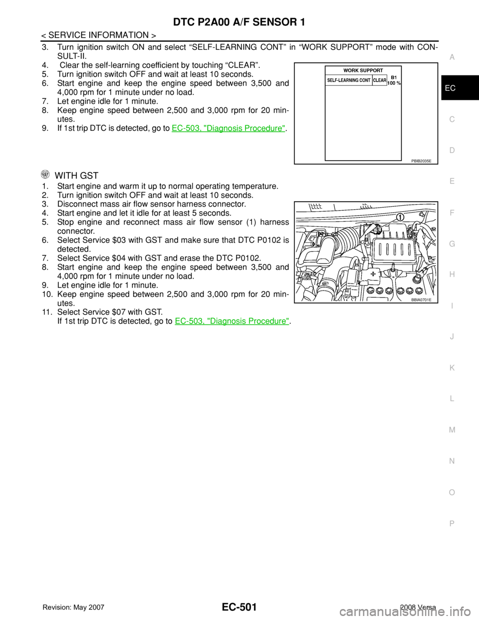
3. Turn ignition switch ON and select “SELF-LEARNING CONT” in “WORK SUPPORT” mode with CON-
SULT-II.
4. Clear the self-learning coefficient by touching “CLEAR”.
5. Turn ignition switch OFF and wait at least 10 seconds.
6. Start engine and keep the engine speed between 3,500 and
4,000 rpm for 1 minute under no load.
7. Let engine idle for 1 minute.
8. Keep engine speed between 2,500 and 3,000 rpm for 20 min-
utes.
9. If 1st trip DTC is detected, go to EC-503, "
Diagnosis Procedure".
WITH GST
1. Start engine and warm it up to normal operating temperature.
2. Turn ignition switch OFF and wait at least 10 seconds.
3. Disconnect mass air flow sensor harness connector.
4. Start engine and let it idle for at least 5 seconds.
5. Stop engine and reconnect mass air flow sensor (1) harness
connector.
6. Select Service $03 with GST and make sure that DTC P0102 is
detected.
7. Select Service $04 with GST and erase the DTC P0102.
8. Start engine and keep the engine speed between 3,500 and
4,000 rpm for 1 minute under no load.
9. Let engine idle for 1 minute.
10. Keep engine speed between 2,500 and 3,000 rpm for 20 min-
utes.
11. Select Service $07 with GST.
If 1st trip DTC is detected, go to EC-503, "
Diagnosis Procedure".
PBIB2035E
BBIA0701E
Page 1578 of 2771
EC-504
< SERVICE INFORMATION >
DTC P2A00 A/F SENSOR 1
3.CHECK FOR INTAKE AIR LEAK
1. Start engine and run it at idle.
2. Listen for an intake air leak after the mass air flow sensor.
OK or NG
OK >> GO TO 4.
NG >> Repair or replace.
4.CLEAR THE SELF-LEARNING DATA
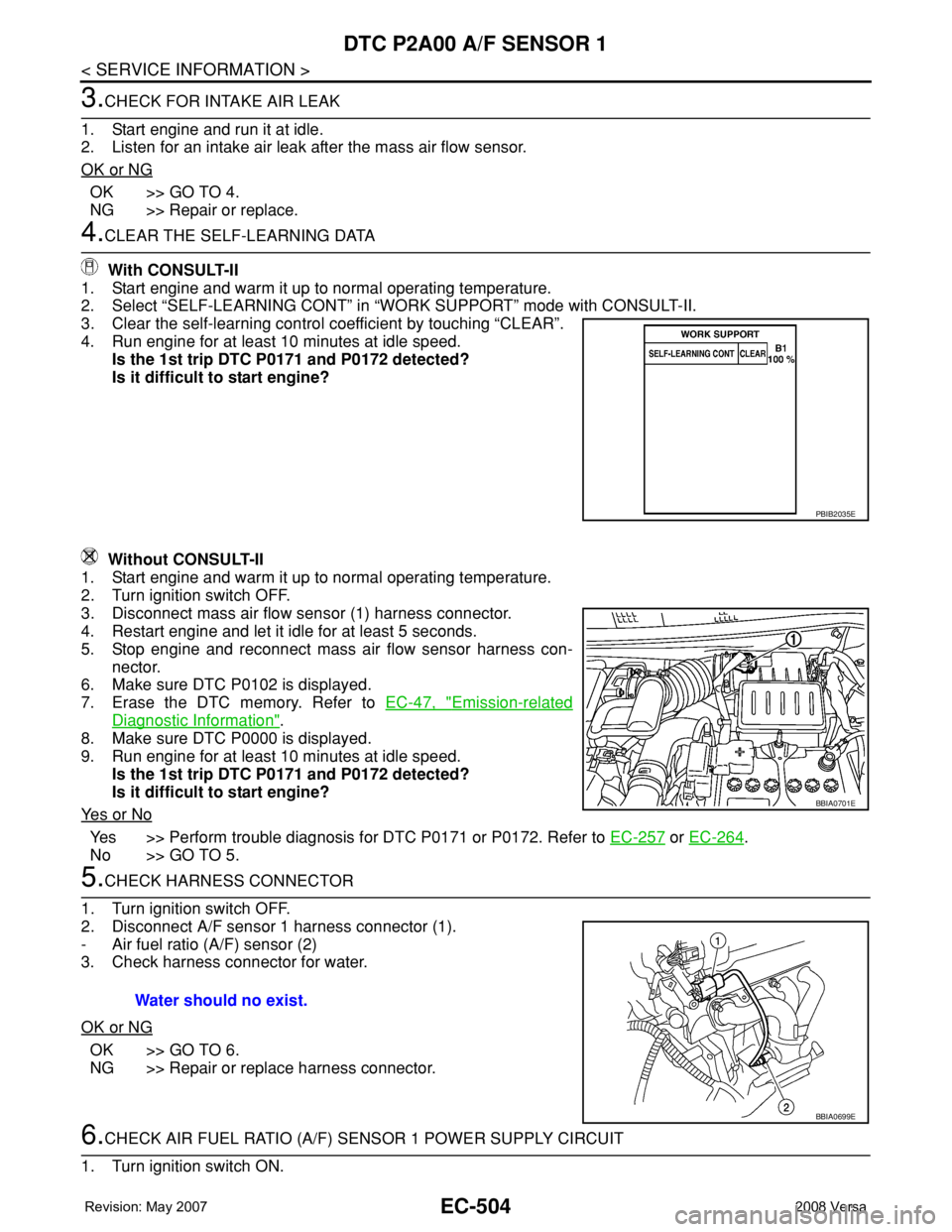
With CONSULT-II
1. Start engine and warm it up to normal operating temperature.
2. Select “SELF-LEARNING CONT” in “WORK SUPPORT” mode with CONSULT-II.
3. Clear the self-learning control coefficient by touching “CLEAR”.
4. Run engine for at least 10 minutes at idle speed.
Is the 1st trip DTC P0171 and P0172 detected?
Is it difficult to start engine?
Without CONSULT-II
1. Start engine and warm it up to normal operating temperature.
2. Turn ignition switch OFF.
3. Disconnect mass air flow sensor (1) harness connector.
4. Restart engine and let it idle for at least 5 seconds.
5. Stop engine and reconnect mass air flow sensor harness con-
nector.
6. Make sure DTC P0102 is displayed.
7. Erase the DTC memory. Refer to EC-47, "
Emission-related
Diagnostic Information".
8. Make sure DTC P0000 is displayed.
9. Run engine for at least 10 minutes at idle speed.
Is the 1st trip DTC P0171 and P0172 detected?
Is it difficult to start engine?
Ye s o r N o
Yes >> Perform trouble diagnosis for DTC P0171 or P0172. Refer to EC-257 or EC-264.
No >> GO TO 5.
5.CHECK HARNESS CONNECTOR
1. Turn ignition switch OFF.
2. Disconnect A/F sensor 1 harness connector (1).
- Air fuel ratio (A/F) sensor (2)
3. Check harness connector for water.
OK or NG
OK >> GO TO 6.
NG >> Repair or replace harness connector.
6.CHECK AIR FUEL RATIO (A/F) SENSOR 1 POWER SUPPLY CIRCUIT
1. Turn ignition switch ON.
PBIB2035E
BBIA0701E
Water should no exist.
BBIA0699E
Page 1580 of 2771
EC-506
< SERVICE INFORMATION >
DTC P2A00 A/F SENSOR 1
• Before installing new air fuel ratio (A/F) sensor, clean exhaust system threads using Heated Oxygen
Sensor Thread Cleaner tool J-43897-18 or J-43897-12 and approved anti-seize lubricant.
>> GO TO 12.
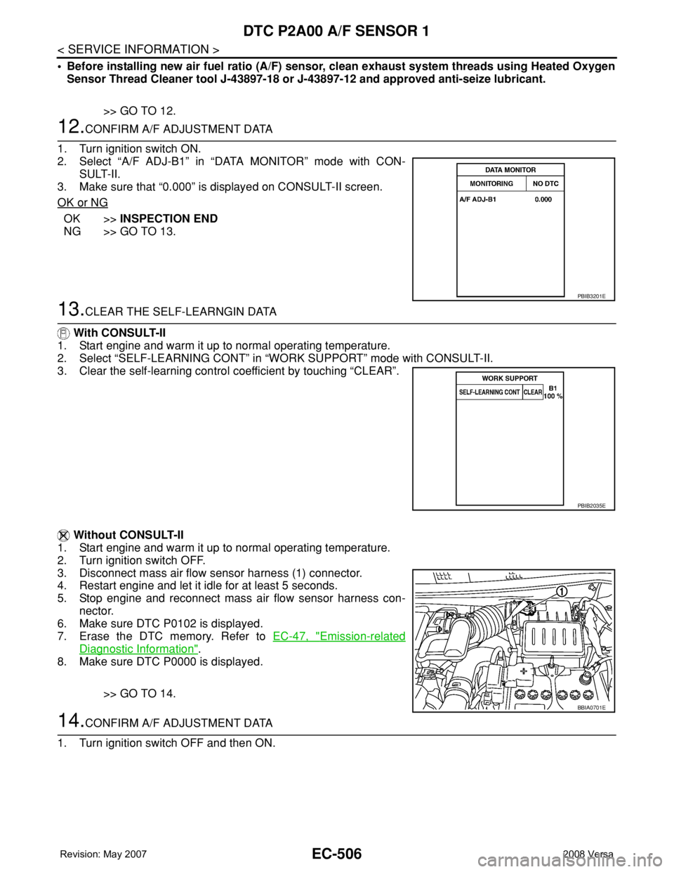
12.CONFIRM A/F ADJUSTMENT DATA
1. Turn ignition switch ON.
2. Select “A/F ADJ-B1” in “DATA MONITOR” mode with CON-
SULT-II.
3. Make sure that “0.000” is displayed on CONSULT-II screen.
OK or NG
OK >>INSPECTION END
NG >> GO TO 13.
13.CLEAR THE SELF-LEARNGIN DATA
With CONSULT-II
1. Start engine and warm it up to normal operating temperature.
2. Select “SELF-LEARNING CONT” in “WORK SUPPORT” mode with CONSULT-II.
3. Clear the self-learning control coefficient by touching “CLEAR”.
Without CONSULT-II
1. Start engine and warm it up to normal operating temperature.
2. Turn ignition switch OFF.
3. Disconnect mass air flow sensor harness (1) connector.
4. Restart engine and let it idle for at least 5 seconds.
5. Stop engine and reconnect mass air flow sensor harness con-
nector.
6. Make sure DTC P0102 is displayed.
7. Erase the DTC memory. Refer to EC-47, "
Emission-related
Diagnostic Information".
8. Make sure DTC P0000 is displayed.
>> GO TO 14.
14.CONFIRM A/F ADJUSTMENT DATA
1. Turn ignition switch OFF and then ON.
PBIB3201E
PBIB2035E
BBIA0701E
Page 1600 of 2771
EC-526
< SERVICE INFORMATION >
FUEL PUMP
FUEL PUMP
DescriptionINFOID:0000000001703065
SYSTEM DESCRIPTION
*: ECM determines the start signal status by the signals of engine speed and battery voltage.
The ECM activates the fuel pump for several seconds after the ignition switch is turned ON to improve engine
startability. If the ECM receives a engine speed signal from the crankshaft position sensor (POS) and cam-
shaft position sensor (PHASE), it knows that the engine is rotating, and causes the pump to operate. If the
engine speed signal is not received when the ignition switch is ON, the engine stalls. The ECM stops pump
operation and prevents battery discharging, thereby improving safety. The ECM does not directly drive the fuel
pump. It controls the ON/OFF fuel pump relay, which in turn controls the fuel pump.
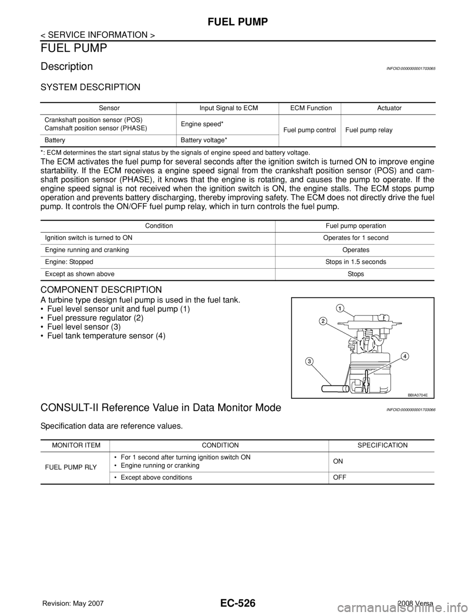
COMPONENT DESCRIPTION
A turbine type design fuel pump is used in the fuel tank.
• Fuel level sensor unit and fuel pump (1)
• Fuel pressure regulator (2)
• Fuel level sensor (3)
• Fuel tank temperature sensor (4)
CONSULT-II Reference Value in Data Monitor ModeINFOID:0000000001703066
Specification data are reference values.
Sensor Input Signal to ECM ECM Function Actuator
Crankshaft position sensor (POS)
Camshaft position sensor (PHASE)Engine speed*
Fuel pump control Fuel pump relay
Battery Battery voltage*
Condition Fuel pump operation
Ignition switch is turned to ON Operates for 1 second
Engine running and crankingOperates
Engine: StoppedStops in 1.5 seconds
Except as shown aboveSt ops
BBIA0704E
MONITOR ITEM CONDITION SPECIFICATION
FUEL PUMP RLY• For 1 second after turning ignition switch ON
• Engine running or crankingON
• Except above conditions OFF
Page 1617 of 2771
REFRIGERANT PRESSURE SENSOR
EC-543
< SERVICE INFORMATION >
C
D
E
F
G
H
I
J
K
L
MA
EC
N
P O
Diagnosis ProcedureINFOID:0000000001703078
1.CHECK REFRIGERANT PRESSURE SENSOR OVERALL FUNCTION
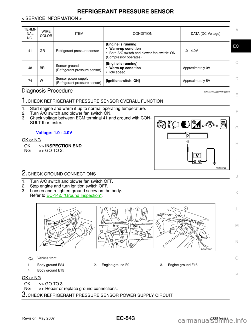
1. Start engine and warm it up to normal operating temperature.
2. Turn A/C switch and blower fan switch ON.
3. Check voltage between ECM terminal 41 and ground with CON-
SULT-II or tester.
OK or NG
OK >>INSPECTION END
NG >> GO TO 2.
2.CHECK GROUND CONNECTIONS
1. Turn A/C switch and blower fan switch OFF.
2. Stop engine and turn ignition switch OFF.
3. Loosen and retighten ground screw on the body.
Refer to EC-142, "
Ground Inspection".
OK or NG
OK >> GO TO 3.
NG >> Repair or replace ground connections.
3.CHECK REFRIGERANT PRESSURE SENSOR POWER SUPPLY CIRCUIT
TERMI-
NAL
NO.WIRE
COLORITEM CONDITION DATA (DC Voltage)
41 GR Refrigerant pressure sensor[Engine is running]
•Warm-up condition
• Both A/C switch and blower fan switch: ON
(Compressor operates)1.0 - 4.0V
48 BRSensor ground
(Refrigerant pressure sensor)[Engine is running]
•Warm-up condition
• Idle speedApproximately 0V
74 WSensor power supply
(Refrigerant pressure sensor)[Ignition switch: ON]Approximately 5V
Voltage: 1.0 - 4.0V
PBIA9574J
:Vehicle front
1. Body ground E24 2. Engine ground F9 3. Engine ground F16
4. Body ground E15
BBIA0698E
Page 1630 of 2771

SQUEAK AND RATTLE TROUBLE DIAGNOSIS
EI-7
< SYMPTOM DIAGNOSIS >
C
D
E
F
G
H
J
K
L
MA
B
EI
N
O
P
The following materials, not found in the kit, can also be used to repair squeaks and rattles.
UHMW (TEFLON) TAPE
Insulates where slight movement is present. Ideal for instrument panel applications.
SILICONE GREASE
Used in place of UHMW tape that will be visible or not fit.
Note: Will only last a few months.
SILICONE SPRAY
Use when grease cannot be applied.
DUCT TAPE
Use to eliminate movement.
CONFIRM THE REPAIR
Confirm that the cause of a noise is repaired by test driving the vehicle. Operate the vehicle under the same
conditions as when the noise originally occurred. Refer to the notes on the Diagnostic Worksheet.
Generic Squeak and Rattle TroubleshootingINFOID:0000000001704215
Refer to Table of Contents for specific component removal and installation information.
INSTRUMENT PANEL
Most incidents are caused by contact and movement between:
1. The cluster lid A and instrument panel
2. Acrylic lens and combination meter housing
3. Instrument panel to front pillar garnish
4. Instrument panel to windshield
5. Instrument panel pins
6. Wiring harnesses behind the combination meter
7. A/C defroster duct and duct joint
These incidents can usually be located by tapping or moving the components to duplicate the noise or by
pressing on the components while driving to stop the noise. Most of these incidents can be repaired by apply-
ing felt cloth tape or silicone spray (in hard to reach areas). Urethane pads can be used to insulate wiring har-
ness.
CAUTION:
Do not use silicone spray to isolate a squeak or rattle. If you saturate the area with silicone, you will
not be able to recheck the repair.
CENTER CONSOLE
Components to pay attention to include:
1. Shifter assembly cover to finisher
2. A/C control unit and cluster lid C
3. Wiring harnesses behind audio and A/C control unit
The instrument panel repair and isolation procedures also apply to the center console.
DOORS
Pay attention to the:
1. Finisher and inner panel making a slapping noise
2. Inside handle escutcheon to door finisher
3. Wiring harnesses tapping
4. Door striker out of alignment causing a popping noise on starts and stops
Tapping or moving the components or pressing on them while driving to duplicate the conditions can isolate
many of these incidents. You can usually insulate the areas with felt cloth tape or insulator foam blocks from
the NISSAN Squeak and Rattle Kit (J-43980) to repair the noise.
TRUNK
Trunk noises are often caused by a loose jack or loose items put into the trunk by the owner.
In addition look for:
1. Trunk lid bumpers out of adjustment
2. Trunk lid striker out of adjustment
Page 1681 of 2771

EM-4
< SERVICE INFORMATION >
PRECAUTIONS
2. Use the Intelligent Key or mechanical key to turn the ignition switch to the ″ACC″ position. At this time, the
steering lock will be released.
3. Disconnect both battery cables. The steering lock will remain released and the steering wheel can be
rotated.
4. Perform the necessary repair operation.
5. When the repair work is completed, return the ignition switch to the ″LOCK″ position before connecting
the battery cables. (At this time, the steering lock mechanism will engage.)
6. Perform a self-diagnosis check of all control units using CONSULT-III.
Precaution for Drain CoolantINFOID:0000000001702463
• Drain coolant when engine is cooled.
Precaution for Disconnecting Fuel PipingINFOID:0000000001702464
• Before starting work, make sure no fire or spark producing items are in the work area.
• Release fuel pressure before disassembly.
• After disconnecting pipes, plug openings to stop fuel leakage.
Precaution for Removal and DisassemblyINFOID:0000000001702465
• When instructed to use special service tools, use the specified tools. Always be careful to work safely, avoid
forceful or uninstructed operations.
• Exercise maximum care to avoid damage to mating or sliding surfaces.
• Cover openings of engine system with tape or the equivalent, if necessary, to seal out foreign materials.
• Mark and arrange disassembly parts in an organized way for easy troubleshooting and assembly.
• When loosening nuts and bolts, as a basic rule, start with the one furthest outside, then the one diagonally
opposite, and so on. If the order of loosening is specified, do exactly as specified. Power tools may be used
where noted in the step.
Precaution for Inspection, Repair and ReplacementINFOID:0000000001702466
• Before repairing or replacing, thoroughly inspect parts. Inspect new replacement parts in the same way, and
replace if necessary.
Precaution for Assembly and InstallationINFOID:0000000001702467
• Use torque wrench to tighten bolts or nuts to specification.
• When tightening nuts and bolts, as a basic rule, equally tighten in several different steps starting with the
ones in center, then ones on inside and outside diagonally in this order. If the order of tightening is specified,
do exactly as specified.
• Replace with new gasket, packing, oil seal or O-ring.
• Thoroughly wash, clean, and air-blow each part. Carefully check oil or coolant passages for any restriction
and blockage.
• Avoid damaging sliding or mating surfaces. Completely remove foreign materials such as cloth lint or dust.
Before assembly, oil sliding surfaces well.
• Release air within route after draining coolant.
• Before starting engine, apply fuel pressure to fuel lines with turning ignition switch ON (with engine stopped).
Then make sure that there are no leaks at fuel line connections.
• After repairing, start engine and increase engine speed to check coolant, fuel, oil, and exhaust systems for
leakage.
Parts Requiring Angular TighteningINFOID:0000000001702468
• Use an angle wrench for the final tightening of the following engine parts:
- Cylinder head bolts
- Camshaft sprocket (INT)
- Main bearing cap bolts
- Connecting rod cap nuts
- Crankshaft pulley bolt (No angle wrench is required as the bolt flange is provided with notches for angular
tightening)
Page 1731 of 2771
EM-54
< SERVICE INFORMATION >
CAMSHAFT
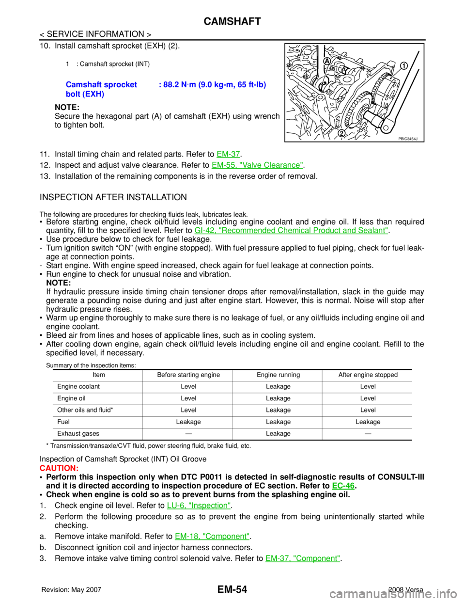
10. Install camshaft sprocket (EXH) (2).
NOTE:
Secure the hexagonal part (A) of camshaft (EXH) using wrench
to tighten bolt.
11. Install timing chain and related parts. Refer to EM-37
.
12. Inspect and adjust valve clearance. Refer to EM-55, "
Valve Clearance".
13. Installation of the remaining components is in the reverse order of removal.
INSPECTION AFTER INSTALLATION
The following are procedures for checking fluids leak, lubricates leak.
• Before starting engine, check oil/fluid levels including engine coolant and engine oil. If less than required
quantity, fill to the specified level. Refer to GI-42, "
Recommended Chemical Product and Sealant".
• Use procedure below to check for fuel leakage.
- Turn ignition switch “ON” (with engine stopped). With fuel pressure applied to fuel piping, check for fuel leak-
age at connection points.
- Start engine. With engine speed increased, check again for fuel leakage at connection points.
• Run engine to check for unusual noise and vibration.
NOTE:
If hydraulic pressure inside timing chain tensioner drops after removal/installation, slack in the guide may
generate a pounding noise during and just after engine start. However, this is normal. Noise will stop after
hydraulic pressure rises.
• Warm up engine thoroughly to make sure there is no leakage of fuel, or any oil/fluids including engine oil and
engine coolant.
• Bleed air from lines and hoses of applicable lines, such as in cooling system.
• After cooling down engine, again check oil/fluid levels including engine oil and engine coolant. Refill to the
specified level, if necessary.
Summary of the inspection items:
* Transmission/transaxle/CVT fluid, power steering fluid, brake fluid, etc.
Inspection of Camshaft Sprocket (INT) Oil Groove
CAUTION:
• Perform this inspection only when DTC P0011 is detected in self-diagnostic results of CONSULT-III
and it is directed according to inspection procedure of EC section. Refer to EC-46
.
• Check when engine is cold so as to prevent burns from the splashing engine oil.
1. Check engine oil level. Refer to LU-6, "
Inspection".
2. Perform the following procedure so as to prevent the engine from being unintentionally started while
checking.
a. Remove intake manifold. Refer to EM-18, "
Component".
b. Disconnect ignition coil and injector harness connectors.
3. Remove intake valve timing control solenoid valve. Refer to EM-37, "
Component".
1 : Camshaft sprocket (INT)
Camshaft sprocket
bolt (EXH): 88.2 N·m (9.0 kg-m, 65 ft-lb)
PBIC3454J
Item Before starting engine Engine running After engine stopped
Engine coolant Level Leakage Level
Engine oil Level Leakage Level
Other oils and fluid* Level Leakage Level
Fuel Leakage Leakage Leakage
Exhaust gases — Leakage —
Page 1739 of 2771
EM-62
< SERVICE INFORMATION >
CYLINDER HEAD
CYLINDER HEAD
On-Vehicle ServiceINFOID:0000000001702501
CHECKING COMPRESSION PRESSURE
1. Warm up engine thoroughly. Then, stop it.
2. Release fuel pressure. Refer to EC-78, "
Fuel Pressure Check".
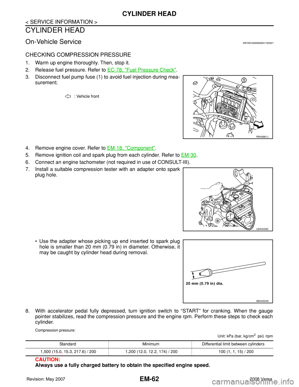
3. Disconnect fuel pump fuse (1) to avoid fuel injection during mea-
surement.
4. Remove engine cover. Refer to EM-18, "
Component".
5. Remove ignition coil and spark plug from each cylinder. Refer to EM-30
.
6. Connect an engine tachometer (not required in use of CONSULT-III).
7. Install a suitable compression tester with an adapter onto spark
plug hole.
• Use the adapter whose picking up end inserted to spark plug
hole is smaller than 20 mm (0.79 in) in diameter. Otherwise, it
may be caught by cylinder head during removal.
8. With accelerator pedal fully depressed, turn ignition switch to “START” for cranking. When the gauge
pointer stabilizes, read the compression pressure and the engine rpm. Perform these steps to check each
cylinder.
Compression pressure:
Unit: kPa (bar, kg/cm2 psi) /rpm
CAUTION:
Always use a fully charged battery to obtain the specified engine speed.
: Vehicle front
PBIA9861J
LBIA0459E
SBIA0533E
Standard Minimum Differential limit between cylinders
1,500 (15.0, 15.3, 217.6) / 200 1,200 (12.0, 12.2, 174) / 200 100 (1, 1, 15) / 200