stop start NISSAN LATIO 2008 Service Workshop Manual
[x] Cancel search | Manufacturer: NISSAN, Model Year: 2008, Model line: LATIO, Model: NISSAN LATIO 2008Pages: 2771, PDF Size: 60.61 MB
Page 1206 of 2771
EC-132
< SERVICE INFORMATION >
TROUBLE DIAGNOSIS - SPECIFICATION VALUE
12.CHECK A/F SENSOR 1 FUNCTION
Perform all DTC Confirmation Procedure related with A/F sensor 1.
• For DTC P0130, refer to EC-206, "
DTC Confirmation Procedure".
• For DTC P0131, refer to EC-213, "
DTC Confirmation Procedure".
• For DTC P0132, refer to EC-219, "
DTC Confirmation Procedure".
• For DTC P0133, refer to EC-225, "
DTC Confirmation Procedure".
• For DTC P2A00, refer to EC-500, "
DTC Confirmation Procedure".
OK or NG
OK >> GO TO 15.
NG >> GO TO 13.
13.CHECK A/F SENSOR 1 CIRCUIT
Perform Diagnostic Procedure according to corresponding DTC.
>> GO TO 14.
14.CHECK “A/F ALPHA-B1”
1. Start engine.
2. Select “A/F ALPHA-B1” in “DATA MONITOR (SPEC)” mode, and make sure that the indication is within
the SP value.
OK or NG
OK >>INSPECTION END
NG >> GO TO 15.
15.DISCONNECT AND RECONNECT ECM HARNESS CONNECTOR
1. Stop the engine.
2. Disconnect ECM harness connector. Check pin terminal and connector for damage, and then reconnect it.
>> GO TO 16.
16.CHECK “A/F ALPHA-B1”
1. Start engine.
2. Select “A/F ALPHA-B1” in “DATA MONITOR (SPEC)” mode, and make sure that the indication is within
the SP value.
OK or NG
OK >>INSPECTION END
NG >> Detect malfunctioning part according to EC-88, "
Symptom Matrix Chart".
17.CHECK “B/FUEL SCHDL”
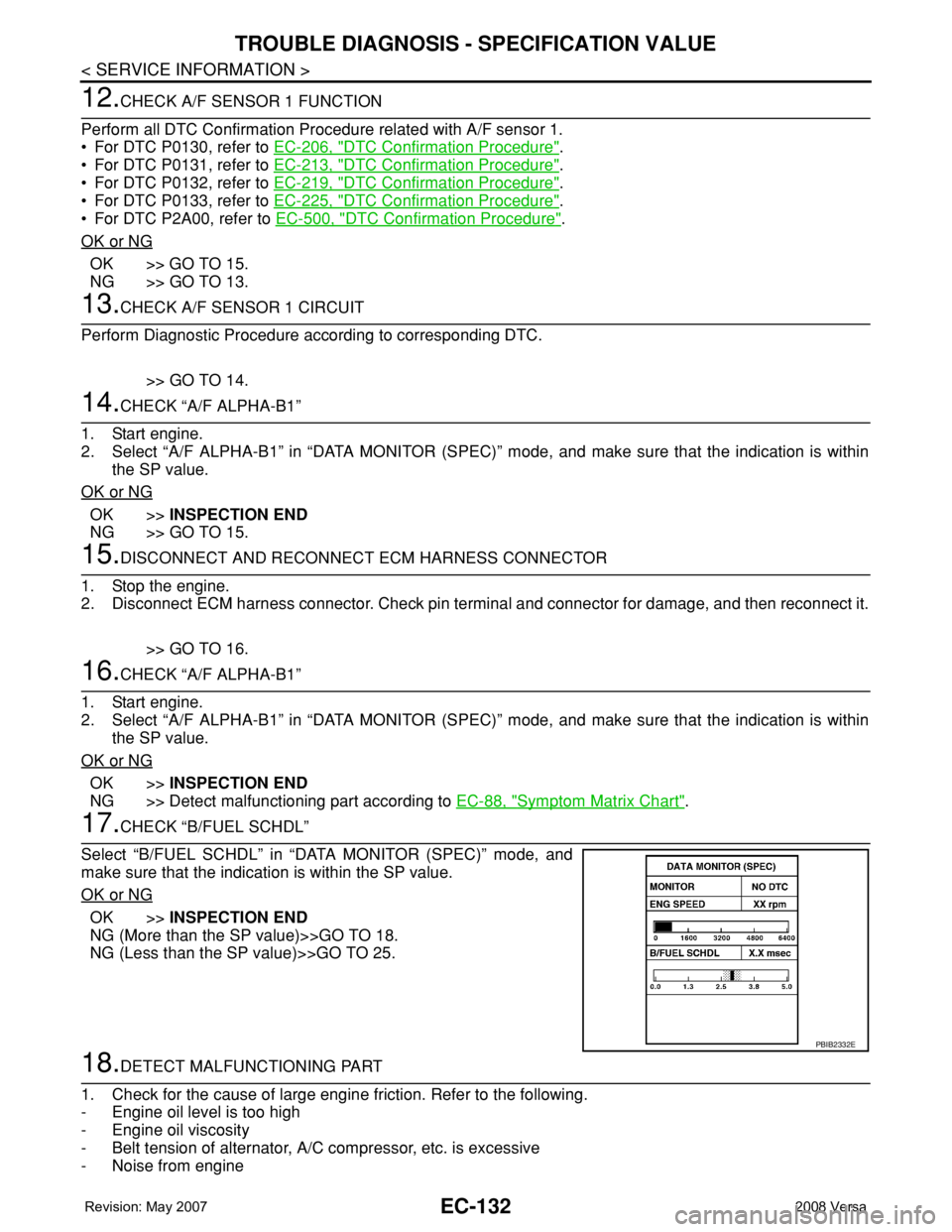
Select “B/FUEL SCHDL” in “DATA MONITOR (SPEC)” mode, and
make sure that the indication is within the SP value.
OK or NG
OK >>INSPECTION END
NG (More than the SP value)>>GO TO 18.
NG (Less than the SP value)>>GO TO 25.
18.DETECT MALFUNCTIONING PART
1. Check for the cause of large engine friction. Refer to the following.
- Engine oil level is too high
- Engine oil viscosity
- Belt tension of alternator, A/C compressor, etc. is excessive
- Noise from engine
PBIB2332E
Page 1207 of 2771
TROUBLE DIAGNOSIS - SPECIFICATION VALUE
EC-133
< SERVICE INFORMATION >
C
D
E
F
G
H
I
J
K
L
MA
EC
N
P O
- Noise from transmission, etc.
2. Check for the cause of insufficient combustion. Refer to the following.
- Valve clearance malfunction
- Intake valve timing control function malfunction
- Camshaft sprocket installation malfunction, etc.
>> Repair or replace malfunctioning part, and then GO TO 30.
19.CHECK INTAKE SYSTEM
Check for the cause of uneven air flow through mass air flow sensor. Refer to the following.
• Crushed air ducts
• Malfunctioning seal of air cleaner element
• Uneven dirt of air cleaner element
• Improper specification of intake air system
OK or NG
OK >> GO TO 21.
NG >> Repair or replace malfunctioning part, and then GO TO 20.
20.CHECK “A/F ALPHA-B1” AND “B/FUEL SCHDL”
Select “A/F ALPHA-B1” and “B/FUEL SCHDL” in “DATA MONITOR (SPEC)” mode, and make sure that the
each indication is within the SP value.
OK or NG
OK >>INSPECTION END
NG (“B/FUEL SCHDL” is more, “A/F ALPHA-B1” is less than the SP value)>>GO TO 21.
21.DISCONNECT AND RECONNECT MASS AIR FLOW SENSOR HARNESS CONNECTOR
1. Stop the engine.
2. Disconnect mass air flow sensor harness connector. Check pin terminal and connector for damage and
then reconnect it again.
>> GO TO 22.
22.CHECK “A/F ALPHA-B1”
1. Start engine.
2. Select “A/F ALPHA-B1” in “DATA MONITOR (SPEC)” mode, and make sure that the indication is within
the SP value.
OK or NG
OK >> 1. Detect malfunctioning part of mass air flow sensor circuit and repair it. Refer to EC-167.
2. GO TO 29.
NG >> GO TO 23.
23.CHECK “MAS A/F SE-B1”
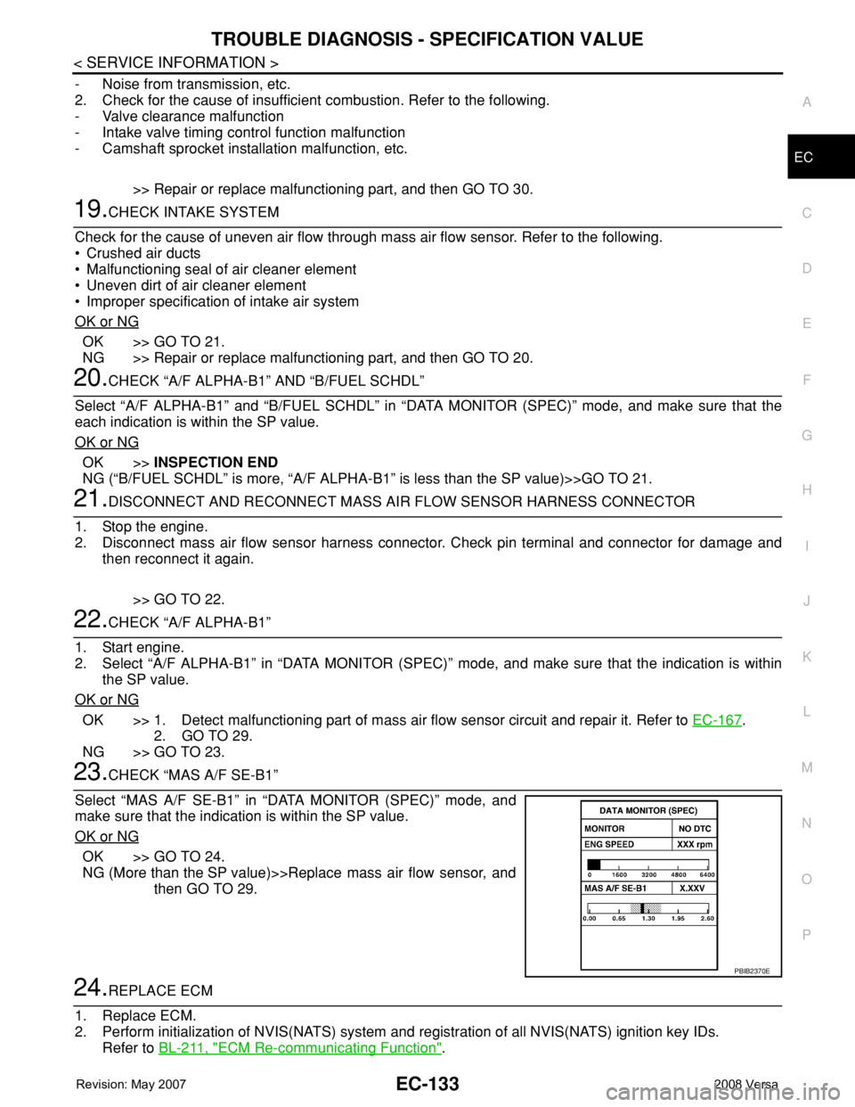
Select “MAS A/F SE-B1” in “DATA MONITOR (SPEC)” mode, and
make sure that the indication is within the SP value.
OK or NG
OK >> GO TO 24.
NG (More than the SP value)>>Replace mass air flow sensor, and
then GO TO 29.
24.REPLACE ECM
1. Replace ECM.
2. Perform initialization of NVIS(NATS) system and registration of all NVIS(NATS) ignition key IDs.
Refer to BL-211, "
ECM Re-communicating Function".
PBIB2370E
Page 1236 of 2771
EC-162
< SERVICE INFORMATION >
DTC P0075 IVT CONTROL SOLENOID VALVE
DTC P0075 IVT CONTROL SOLENOID VALVE
Component DescriptionINFOID:0000000001702640
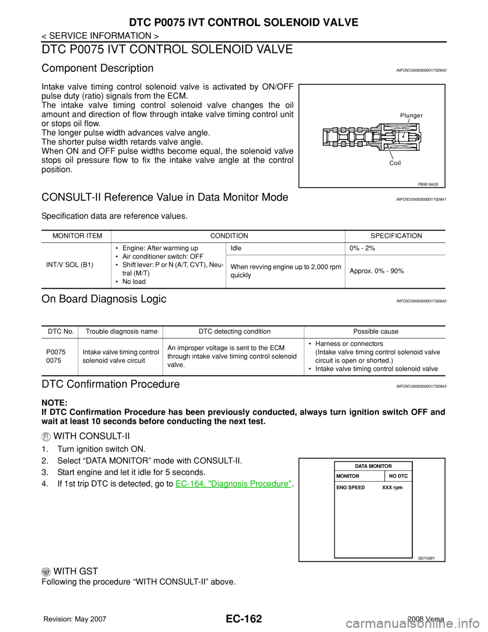
Intake valve timing control solenoid valve is activated by ON/OFF
pulse duty (ratio) signals from the ECM.
The intake valve timing control solenoid valve changes the oil
amount and direction of flow through intake valve timing control unit
or stops oil flow.
The longer pulse width advances valve angle.
The shorter pulse width retards valve angle.
When ON and OFF pulse widths become equal, the solenoid valve
stops oil pressure flow to fix the intake valve angle at the control
position.
CONSULT-II Reference Value in Data Monitor ModeINFOID:0000000001702641
Specification data are reference values.
On Board Diagnosis LogicINFOID:0000000001702642
DTC Confirmation ProcedureINFOID:0000000001702643
NOTE:
If DTC Confirmation Procedure has been previously conducted, always turn ignition switch OFF and
wait at least 10 seconds before conducting the next test.
WITH CONSULT-II
1. Turn ignition switch ON.
2. Select “DATA MONITOR” mode with CONSULT-II.
3. Start engine and let it idle for 5 seconds.
4. If 1st trip DTC is detected, go to EC-164, "
Diagnosis Procedure".
WITH GST
Following the procedure “WITH CONSULT-II” above.
PBIB1842E
MONITOR ITEM CONDITION SPECIFICATION
INT/V SOL (B1)• Engine: After warming up
• Air conditioner switch: OFF
• Shift lever: P or N (A/T, CVT), Neu-
tral (M/T)
•No loadIdle 0% - 2%
When revving engine up to 2,000 rpm
quicklyApprox. 0% - 90%
DTC No. Trouble diagnosis name DTC detecting condition Possible cause
P0075
0075Intake valve timing control
solenoid valve circuitAn improper voltage is sent to the ECM
through intake valve timing control solenoid
valve.• Harness or connectors
(Intake valve timing control solenoid valve
circuit is open or shorted.)
• Intake valve timing control solenoid valve
SEF058Y
Page 1242 of 2771
EC-168
< SERVICE INFORMATION >
DTC P0101 MAF SENSOR
PROCEDURE FOR MALFUNCTION A
NOTE:
If engine will not start or stops soon, wait at least 10 seconds with engine stopped (Ignition switch ON) instead
of running engine at idle speed.
With CONSULT-II
1. Turn ignition switch ON.
2. Select “DATA MONITOR” mode with CONSULT-II.
3. Start engine and warm it up to normal operating temperature.
4. Run engine for at least 10 seconds at idle speed.
5. If 1st trip DTC is detected, go to EC-171, "
Diagnosis Procedure".
With GST
Follow the procedure “With CONSULT-II” above.
PROCEDURE FOR MALFUNCTION B
CAUTION:
Always drive vehicle at a safe speed.
With CONSULT-II
1. Turn ignition switch ON.
2. Start engine and warm it up to normal operating temperature.
If engine cannot be started, go to EC-171, "
Diagnosis Procedure".
3. Select “DATA MONITOR” mode with CONSULT-II.
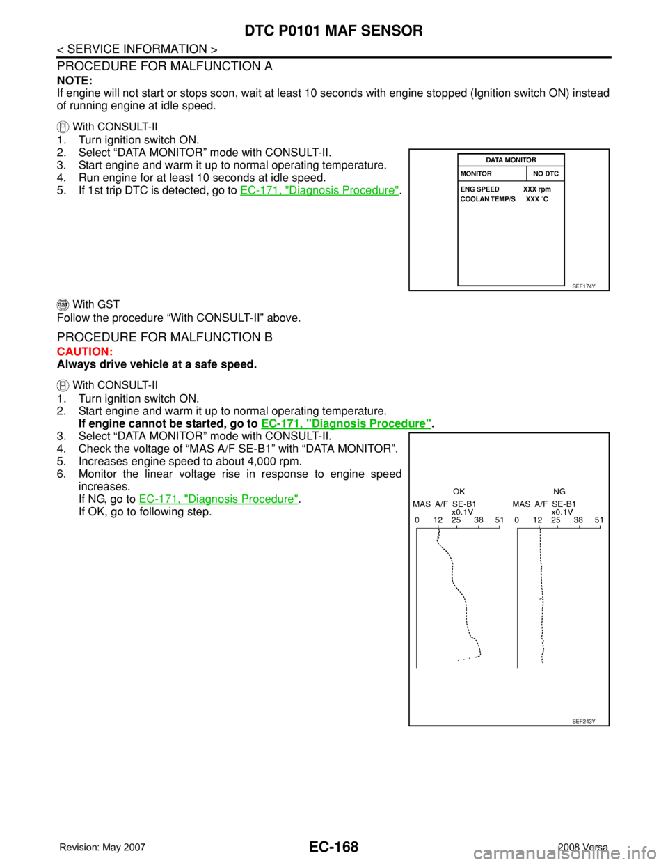
4. Check the voltage of “MAS A/F SE-B1” with “DATA MONITOR”.
5. Increases engine speed to about 4,000 rpm.
6. Monitor the linear voltage rise in response to engine speed
increases.
If NG, go to EC-171, "
Diagnosis Procedure".
If OK, go to following step.
SEF174Y
SEF243Y
Page 1247 of 2771
DTC P0101 MAF SENSOR
EC-173
< SERVICE INFORMATION >
C
D
E
F
G
H
I
J
K
L
MA
EC
N
P O
2. Also check harness for short to ground and short to power.
OK or NG
OK >> GO TO 8.
NG >> Repair open circuit or short to ground or short or short to power in harness or connectors.
8.CHECK INTAKE AIR TEMPERATURE SENSOR
Refer to EC-202, "
Component Inspection".
OK or NG
OK >> GO TO 9.
NG >> Replace intake air temperature sensor.
9.CHECK EVAP CONTROL SYSTEM PRESSURE SENSOR
Refer to EC-353, "
Component Inspection".
OK or NG
OK >> GO TO 10.
NG >> Replace EVAP control system pressure sensor.
10.CHECK MASS AIR FLOW SENSOR
Refer to EC-173, "
Component Inspection".
OK or NG
OK >> GO TO 11.
NG >> Replace mass air flow sensor.
11 .CHECK INTERMITTENT INCIDENT
Perform EC-136
.
>>INSPECTION END
Component InspectionINFOID:0000000001702655
MASS AIR FLOW SENSOR
With CONSULT-II
1. Reconnect all harness connectors disconnected.
2. Start engine and warm it up to normal operating temperature.
3. Connect CONSULT-II and select “DATA MONITOR” mode.
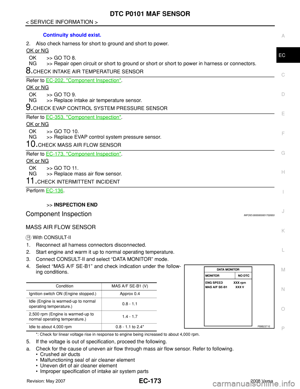
4. Select “MAS A/F SE-B1” and check indication under the follow-
ing conditions.
*: Check for linear voltage rise in response to engine being increased to about 4,000 rpm.
5. If the voltage is out of specification, proceed the following.
a. Check for the cause of uneven air flow through mass air flow sensor. Refer to following.
• Crushed air ducts
• Malfunctioning seal of air cleaner element
• Uneven dirt of air cleaner element
• Improper specification of intake air system partsContinuity should exist.
Condition MAS A/F SE-B1 (V)
Ignition switch ON (Engine stopped.) Approx 0.4
Idle (Engine is warmed-up to normal
operating temperature.)0.8 - 1.1
2,500 rpm (Engine is warmed-up to
normal operating temperature.)1.4 - 1.7
Idle to about 4,000 rpm 0.8 - 1.1 to 2.4*
PBIB2371E
Page 1248 of 2771
EC-174
< SERVICE INFORMATION >
DTC P0101 MAF SENSOR
b. If NG, repair or replace malfunctioning part and perform step 2 to 4 again.
If OK, go to next step.
6. Turn ignition switch OFF.
7. Disconnect mass air flow sensor harness connector and reconnect it again.
8. Perform step 2 to 4 again.
9. If NG, clean or replace mass air flow sensor.
Without CONSULT-II
1. Reconnect all harness connectors disconnected.
2. Start engine and warm it up to normal operating temperature.
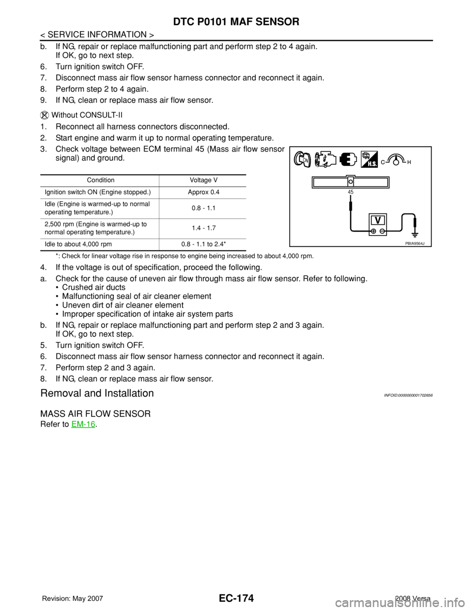
3. Check voltage between ECM terminal 45 (Mass air flow sensor
signal) and ground.
*: Check for linear voltage rise in response to engine being increased to about 4,000 rpm.
4. If the voltage is out of specification, proceed the following.
a. Check for the cause of uneven air flow through mass air flow sensor. Refer to following.
• Crushed air ducts
• Malfunctioning seal of air cleaner element
• Uneven dirt of air cleaner element
• Improper specification of intake air system parts
b. If NG, repair or replace malfunctioning part and perform step 2 and 3 again.
If OK, go to next step.
5. Turn ignition switch OFF.
6. Disconnect mass air flow sensor harness connector and reconnect it again.
7. Perform step 2 and 3 again.
8. If NG, clean or replace mass air flow sensor.
Removal and InstallationINFOID:0000000001702656
MASS AIR FLOW SENSOR
Refer to EM-16.
Condition Voltage V
Ignition switch ON (Engine stopped.) Approx 0.4
Idle (Engine is warmed-up to normal
operating temperature.)0.8 - 1.1
2,500 rpm (Engine is warmed-up to
normal operating temperature.)1.4 - 1.7
Idle to about 4,000 rpm 0.8 - 1.1 to 2.4*
PBIA9564J
Page 1254 of 2771
EC-180
< SERVICE INFORMATION >
DTC P0102, P0103 MAF SENSOR
2. Also check harness for short to ground and short to power.
OK or NG
OK >> GO TO 8.
NG >> Repair open circuit or short to ground or short to power in harness or connectors.
8.CHECK MASS AIR FLOW SENSOR
Refer to EC-180, "
Component Inspection".
OK or NG
OK >> GO TO 9.
NG >> Replace mass air flow sensor.
9.CHECK INTERMITTENT INCIDENT
Refer to EC-136
.
>>INSPECTION END
Component InspectionINFOID:0000000001702663
MASS AIR FLOW SENSOR
With CONSULT-II
1. Reconnect all harness connectors disconnected.
2. Start engine and warm it up to normal operating temperature.
3. Connect CONSULT-II and select “DATA MONITOR” mode.
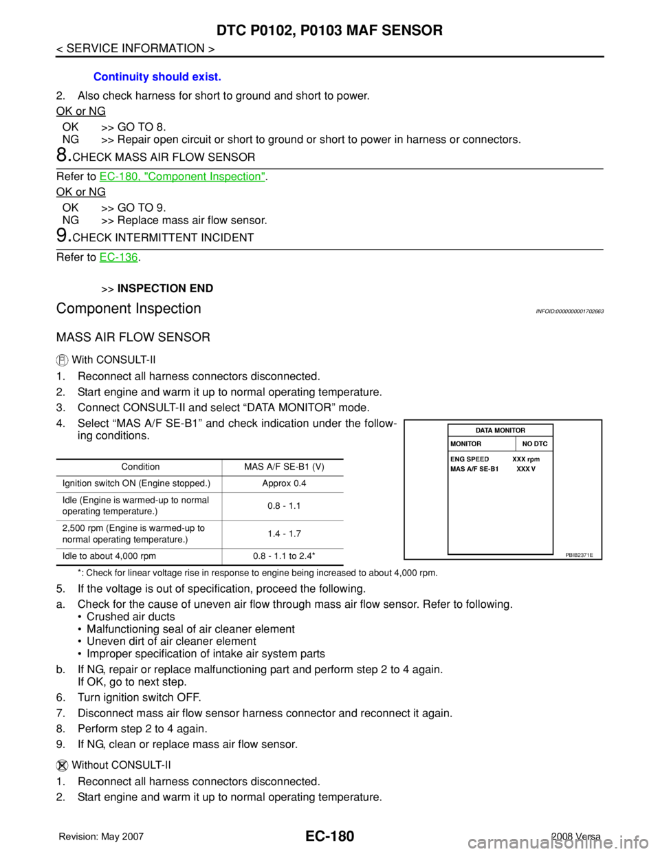
4. Select “MAS A/F SE-B1” and check indication under the follow-
ing conditions.
*: Check for linear voltage rise in response to engine being increased to about 4,000 rpm.
5. If the voltage is out of specification, proceed the following.
a. Check for the cause of uneven air flow through mass air flow sensor. Refer to following.
• Crushed air ducts
• Malfunctioning seal of air cleaner element
• Uneven dirt of air cleaner element
• Improper specification of intake air system parts
b. If NG, repair or replace malfunctioning part and perform step 2 to 4 again.
If OK, go to next step.
6. Turn ignition switch OFF.
7. Disconnect mass air flow sensor harness connector and reconnect it again.
8. Perform step 2 to 4 again.
9. If NG, clean or replace mass air flow sensor.
Without CONSULT-II
1. Reconnect all harness connectors disconnected.
2. Start engine and warm it up to normal operating temperature.Continuity should exist.
Condition MAS A/F SE-B1 (V)
Ignition switch ON (Engine stopped.) Approx 0.4
Idle (Engine is warmed-up to normal
operating temperature.)0.8 - 1.1
2,500 rpm (Engine is warmed-up to
normal operating temperature.)1.4 - 1.7
Idle to about 4,000 rpm 0.8 - 1.1 to 2.4*
PBIB2371E
Page 1273 of 2771
DTC P0125 ECT SENSOR
EC-199
< SERVICE INFORMATION >
C
D
E
F
G
H
I
J
K
L
MA
EC
N
P O
2. Select “DATA MONITOR” mode with CONSULT-II.
3. Check that “COOLAN TEMP/S” is above 10°C (50°F).
If it is above 10°C (50°F), the test result will be OK.
If it is below 10°C (50°F), go to following step.
4. Start engine and run it for 65 minutes at idle speed.
If “COOLAN TEMP/S” increases to more than 10°C (50°F)
within 65 minutes, stop engine because the test result will
be OK.
5. If DTC is detected, go to EC-199, "
Diagnosis Procedure".
WITH GST
Follow the procedure “WITH CONSULT-II” above.
Diagnosis ProcedureINFOID:0000000001702690
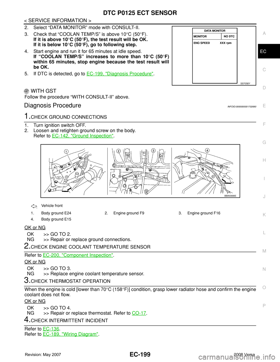
1.CHECK GROUND CONNECTIONS
1. Turn ignition switch OFF.
2. Loosen and retighten ground screw on the body.
Refer to EC-142, "
Ground Inspection".
OK or NG
OK >> GO TO 2.
NG >> Repair or replace ground connections.
2.CHECK ENGINE COOLANT TEMPERATURE SENSOR
Refer to EC-200, "
Component Inspection".
OK or NG
OK >> GO TO 3.
NG >> Replace engine coolant temperature sensor.
3.CHECK THERMOSTAT OPERATION
When the engine is cold [lower than 70°C (158°F)] condition, grasp lower radiator hose and confirm the engine
coolant does not flow.
OK or NG
OK >> GO TO 4.
NG >> Repair or replace thermostat. Refer to CO-17
.
4.CHECK INTERMITTENT INCIDENT
Refer to EC-136
.
Refer to EC-189, "
Wiring Diagram".
SEF058Y
:Vehicle front
1. Body ground E24 2. Engine ground F9 3. Engine ground F16
4. Body ground E15
BBIA0698E
Page 1282 of 2771

EC-208
< SERVICE INFORMATION >
DTC P0130 A/F SENSOR 1
8. Make sure that “TESTING” changes to “COMPLETED”.
If “TESTING” changed to “OUT OF CONDITION”, retry from
step 6.
9. Make sure that “OK” is displayed after touching “SELF-DIAG
RESULT”.
If “NG” is displayed, go to EC-210, "
Diagnosis Procedure".
Overall Function CheckINFOID:0000000001702708
PROCEDURE MALFUNCTION B
Use this procedure to check the overall function of the A/F sensor 1 circuit. During this check, a 1st trip DTC
might not be confirmed.
With GST
1. Start engine and warm it up to normal operating temperature.
2. Drive the vehicle at a speed of 80 km/h (50 MPH) for a few minutes in the suitable gear position.
3. Set shift lever to D position with OD ON (A/T), D position (CVT) or 5th position (M/T), then release the
accelerator pedal fully until the vehicle speed decreases to 50 km/h (30 MPH).
NOTE:
Never apply brake during releasing the accelerator pedal.
4. Repeat steps 2 and 3 for five times.
5. Stop the vehicle and turn ignition switch OFF.
6. Wait at least 10 seconds and restart engine.
7. Repeat steps 2 and 3 for five times.
8. Stop the vehicle and connect GST to the vehicle.
9. Make sure that no 1st trip DTC is displayed.
If the 1st trip DTC is displayed, go to EC-210, "
Diagnosis Procedure".
SEF578Z
Page 1304 of 2771
EC-230
< SERVICE INFORMATION >
DTC P0133 A/F SENSOR 1
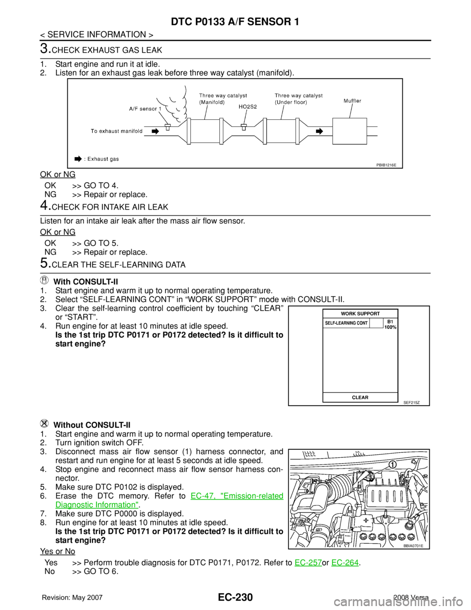
3.CHECK EXHAUST GAS LEAK
1. Start engine and run it at idle.
2. Listen for an exhaust gas leak before three way catalyst (manifold).
OK or NG
OK >> GO TO 4.
NG >> Repair or replace.
4.CHECK FOR INTAKE AIR LEAK
Listen for an intake air leak after the mass air flow sensor.
OK or NG
OK >> GO TO 5.
NG >> Repair or replace.
5.CLEAR THE SELF-LEARNING DATA
With CONSULT-II
1. Start engine and warm it up to normal operating temperature.
2. Select “SELF-LEARNING CONT” in “WORK SUPPORT” mode with CONSULT-II.
3. Clear the self-learning control coefficient by touching “CLEAR”
or “START”.
4. Run engine for at least 10 minutes at idle speed.
Is the 1st trip DTC P0171 or P0172 detected? Is it difficult to
start engine?
Without CONSULT-II
1. Start engine and warm it up to normal operating temperature.
2. Turn ignition switch OFF.
3. Disconnect mass air flow sensor (1) harness connector, and
restart and run engine for at least 5 seconds at idle speed.
4. Stop engine and reconnect mass air flow sensor harness con-
nector.
5. Make sure DTC P0102 is displayed.
6. Erase the DTC memory. Refer to EC-47, "
Emission-related
Diagnostic Information".
7. Make sure DTC P0000 is displayed.
8. Run engine for at least 10 minutes at idle speed.
Is the 1st trip DTC P0171 or P0172 detected? Is it difficult to
start engine?
Ye s o r N o
Yes >> Perform trouble diagnosis for DTC P0171, P0172. Refer to EC-257or EC-264.
No >> GO TO 6.
PBIB1216E
SEF215Z
BBIA0701E