coolant level NISSAN LATIO 2008 Service Repair Manual
[x] Cancel search | Manufacturer: NISSAN, Model Year: 2008, Model line: LATIO, Model: NISSAN LATIO 2008Pages: 2771, PDF Size: 60.61 MB
Page 825 of 2771
CO-8
< SERVICE INFORMATION >
ENGINE COOLANT
ENGINE COOLANT
InspectionINFOID:0000000001702529
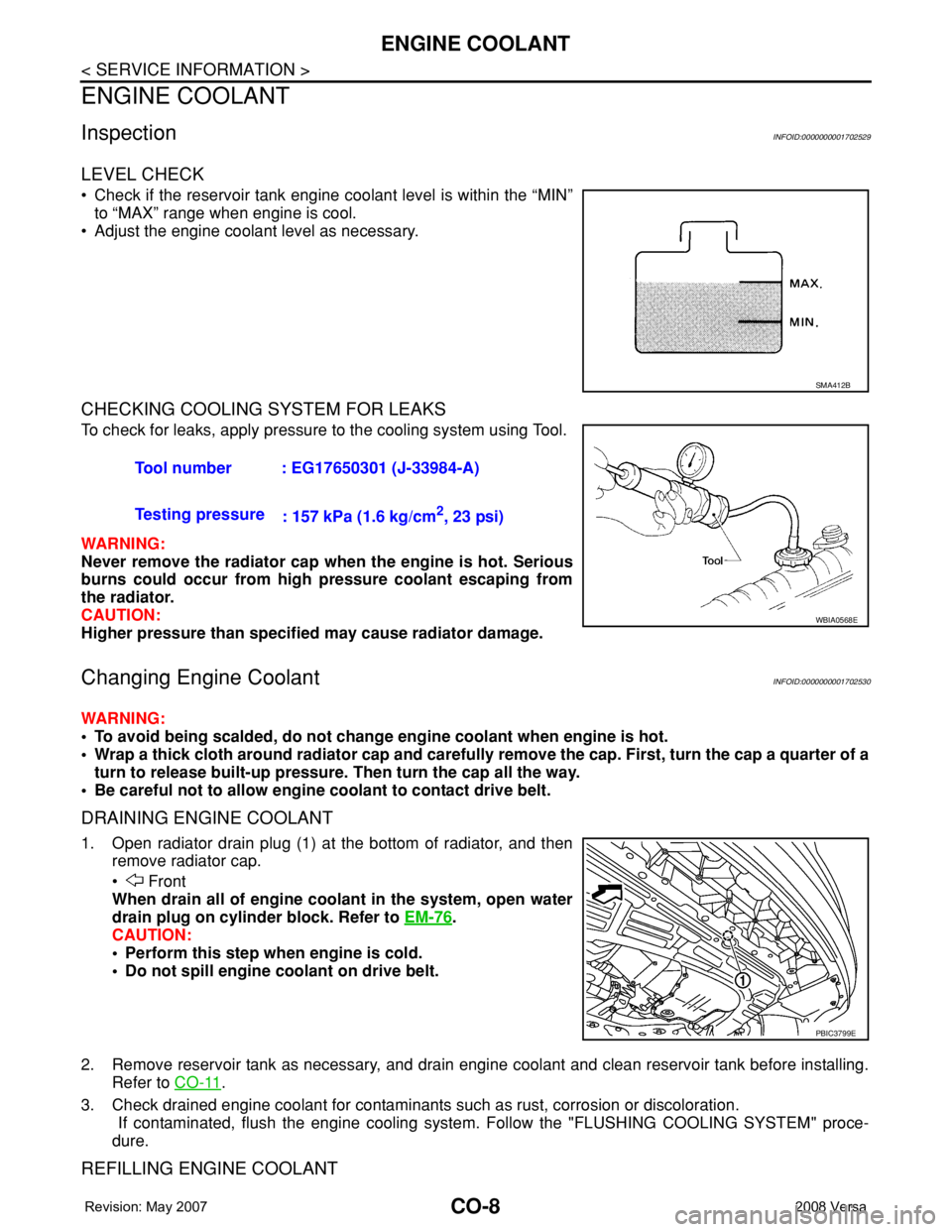
LEVEL CHECK
• Check if the reservoir tank engine coolant level is within the “MIN”
to “MAX” range when engine is cool.
• Adjust the engine coolant level as necessary.
CHECKING COOLING SYSTEM FOR LEAKS
To check for leaks, apply pressure to the cooling system using Tool.
WARNING:
Never remove the radiator cap when the engine is hot. Serious
burns could occur from high pressure coolant escaping from
the radiator.
CAUTION:
Higher pressure than specified may cause radiator damage.
Changing Engine CoolantINFOID:0000000001702530
WARNING:
• To avoid being scalded, do not change engine coolant when engine is hot.
• Wrap a thick cloth around radiator cap and carefully remove the cap. First, turn the cap a quarter of a
turn to release built-up pressure. Then turn the cap all the way.
• Be careful not to allow engine coolant to contact drive belt.
DRAINING ENGINE COOLANT
1. Open radiator drain plug (1) at the bottom of radiator, and then
remove radiator cap.
• Front
When drain all of engine coolant in the system, open water
drain plug on cylinder block. Refer to EM-76
.
CAUTION:
• Perform this step when engine is cold.
• Do not spill engine coolant on drive belt.
2. Remove reservoir tank as necessary, and drain engine coolant and clean reservoir tank before installing.
Refer to CO-11
.
3. Check drained engine coolant for contaminants such as rust, corrosion or discoloration.
If contaminated, flush the engine cooling system. Follow the "FLUSHING COOLING SYSTEM" proce-
dure.
REFILLING ENGINE COOLANT
SMA412B
Tool number : EG17650301 (J-33984-A)
Testing pressure
: 157 kPa (1.6 kg/cm
2, 23 psi)
WBIA0568E
PBIC3799E
Page 826 of 2771
ENGINE COOLANT
CO-9
< SERVICE INFORMATION >
C
D
E
F
G
H
I
J
K
L
MA
CO
N
P O
1. Install reservoir tank if removed. Refer to CO-11.
2. Install radiator drain plug.
•If water drain plug on cylinder block is removed, close and tighten it. Refer to EM-76
.
CAUTION:
Be sure to clean radiator drain plug and install with new O-ring. Refer to CO-11, "
Component".
3. Make sure that each hose clamp has been firmly tightened.
4. Remove air duct assembly. Refer to EM-16
.
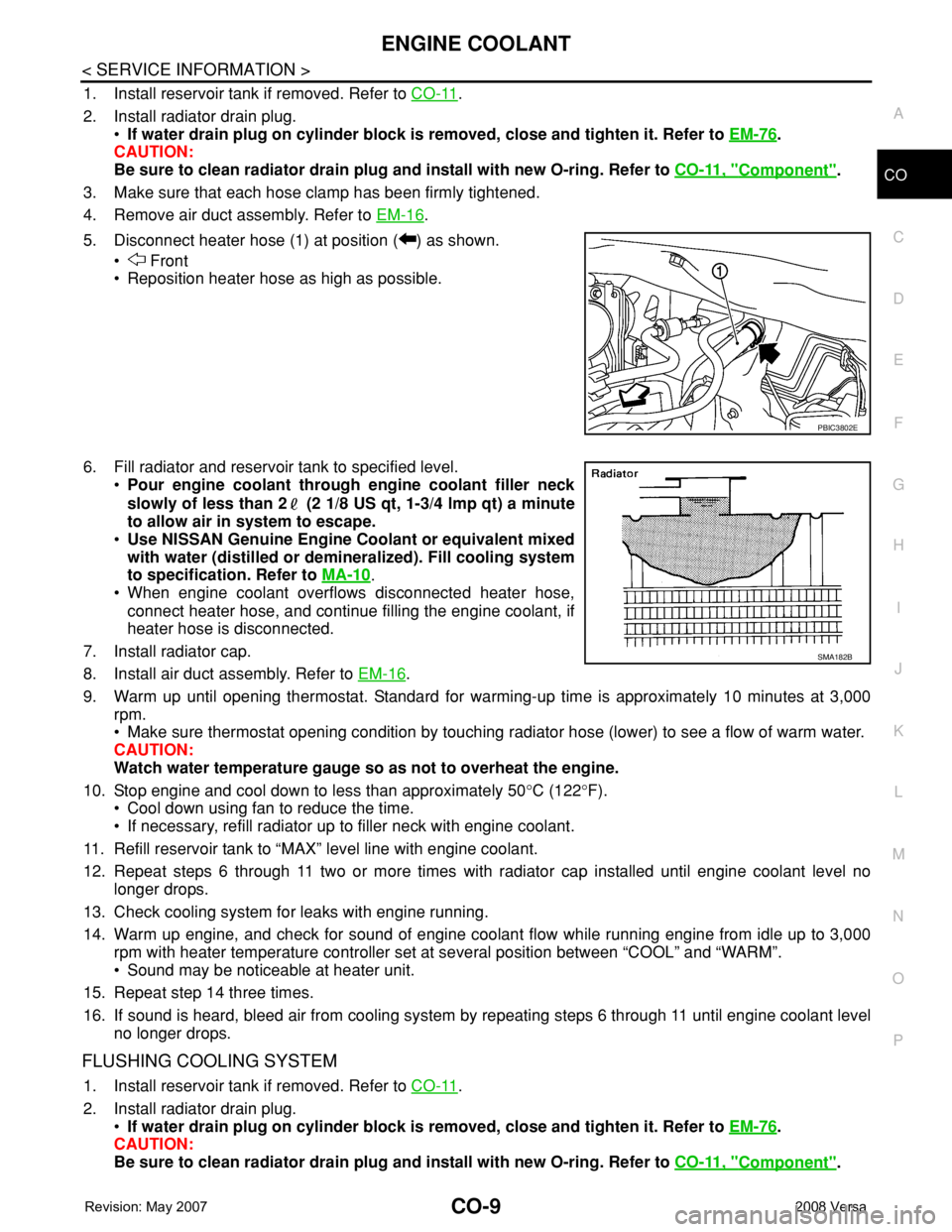
5. Disconnect heater hose (1) at position ( ) as shown.
• Front
• Reposition heater hose as high as possible.
6. Fill radiator and reservoir tank to specified level.
•Pour engine coolant through engine coolant filler neck
slowly of less than 2 (2 1/8 US qt, 1-3/4 lmp qt) a minute
to allow air in system to escape.
•Use NISSAN Genuine Engine Coolant or equivalent mixed
with water (distilled or demineralized). Fill cooling system
to specification. Refer to MA-10
.
• When engine coolant overflows disconnected heater hose,
connect heater hose, and continue filling the engine coolant, if
heater hose is disconnected.
7. Install radiator cap.
8. Install air duct assembly. Refer to EM-16
.
9. Warm up until opening thermostat. Standard for warming-up time is approximately 10 minutes at 3,000
rpm.
• Make sure thermostat opening condition by touching radiator hose (lower) to see a flow of warm water.
CAUTION:
Watch water temperature gauge so as not to overheat the engine.
10. Stop engine and cool down to less than approximately 50°C (122°F).
• Cool down using fan to reduce the time.
• If necessary, refill radiator up to filler neck with engine coolant.
11. Refill reservoir tank to “MAX” level line with engine coolant.
12. Repeat steps 6 through 11 two or more times with radiator cap installed until engine coolant level no
longer drops.
13. Check cooling system for leaks with engine running.
14. Warm up engine, and check for sound of engine coolant flow while running engine from idle up to 3,000
rpm with heater temperature controller set at several position between “COOL” and “WARM”.
• Sound may be noticeable at heater unit.
15. Repeat step 14 three times.
16. If sound is heard, bleed air from cooling system by repeating steps 6 through 11 until engine coolant level
no longer drops.
FLUSHING COOLING SYSTEM
1. Install reservoir tank if removed. Refer to CO-11.
2. Install radiator drain plug.
•If water drain plug on cylinder block is removed, close and tighten it. Refer to EM-76
.
CAUTION:
Be sure to clean radiator drain plug and install with new O-ring. Refer to CO-11, "
Component".
PBIC3802E
SMA182B
Page 839 of 2771

CO-22
< SERVICE INFORMATION >
SERVICE DATA AND SPECIFICATIONS (SDS)
SERVICE DATA AND SPECIFICATIONS (SDS)
Standard and LimitINFOID:0000000001702545
CAPACITY
Unit: (US qt, lmp qt)
THERMOSTAT
WATER CONTROL VALVE
RADIATOR
Unit: kPa (bar, kg/cm2, psi)
Engine coolant capacity (with reservoir tank at “MAX” level) Approx. 6.8 (7 1/4, 6.0)
Valve opening temperature 80.5 - 83.5°C (177 - 182°F)
Maximum valve lift 8 mm/ 95°C (0.315 in/ 203°F)
Valve closing temperature 77°C (171°F)
Valve opening temperature 93.5 - 96.5°C (200 - 206°F)
Maximum valve lift 8 mm/ 108°C (0.315 in/ 226°F)
Valve closing temperature 90°C (194°F)
Cap relief pressureStandard 78 - 98 (0.78 - 0.98, 0.8 - 1.0, 11- 14)
Limit 59 (0.59, 0.6, 9)
Leakage test pressure 157 (1.57, 1.6, 23)
Page 1032 of 2771
COMBINATION METERS
DI-11
< SERVICE INFORMATION >
C
D
E
F
G
H
I
J
L
MA
B
DI
N
O
P
Self-Diagnosis Mode of Combination MeterINFOID:0000000001704497
SELF-DIAGNOSIS MODE FUNCTION
• Self-diagnosis can check for continuity between meter control circuit and each meter (speedometer, tachom-
eter and fuel gauge).
• Self-diagnosis can check for odo/trip meter and A/T indicator (with A/T) or CVT indicator (with CVT) seg-
ment, low-fuel level warning lamp, low water temperature indicator lamp, and high water temperature warn-
ing lamp.
OPERATION PROCEDURE
1. Turn the ignition switch ON, and switch the odo/trip meter to “trip A” or “trip B”.
NOTE:
13 B Illumination control switch (-) — — Refer to LT- 1 0 5 , "System Description" .
17 GWasher fluid level switch
(Canada models)ONWasher fluid level low 0
Washer fluid level normal Battery voltage
21
BGround — — 0 22
23
24 V Fuel level sensor ground (-) ON — 0
26 BVehicle speed sensor ground
(without ABS or CVT)ON — 0
27 G Battery power supply OFF — Battery voltage
28 SB Ignition switch ON or START ON — Battery voltage
29 GR Seat belt buckle switch RH ONUnfastened (ON) 0
Fastened (OFF) Battery voltage
30 G Stop lamp switch ONBrake pedal depressed Battery voltage
Brake pedal released 0
31 V A/T N-range input (with A/T) ONTransmission gear selector lever
in N positionBattery voltage
Transmission gear selector lever
other than N position0
32 W A/T P-range input (with A/T) ONTransmission gear selector lever
in P positionBattery voltage
Transmission gear selector lever
other than P position0
33 Y A/T PN output (with A/T) ONTransmission gear selector lever
in P or N position0
Transmission gear selector lever
other than P or N positionBattery voltage
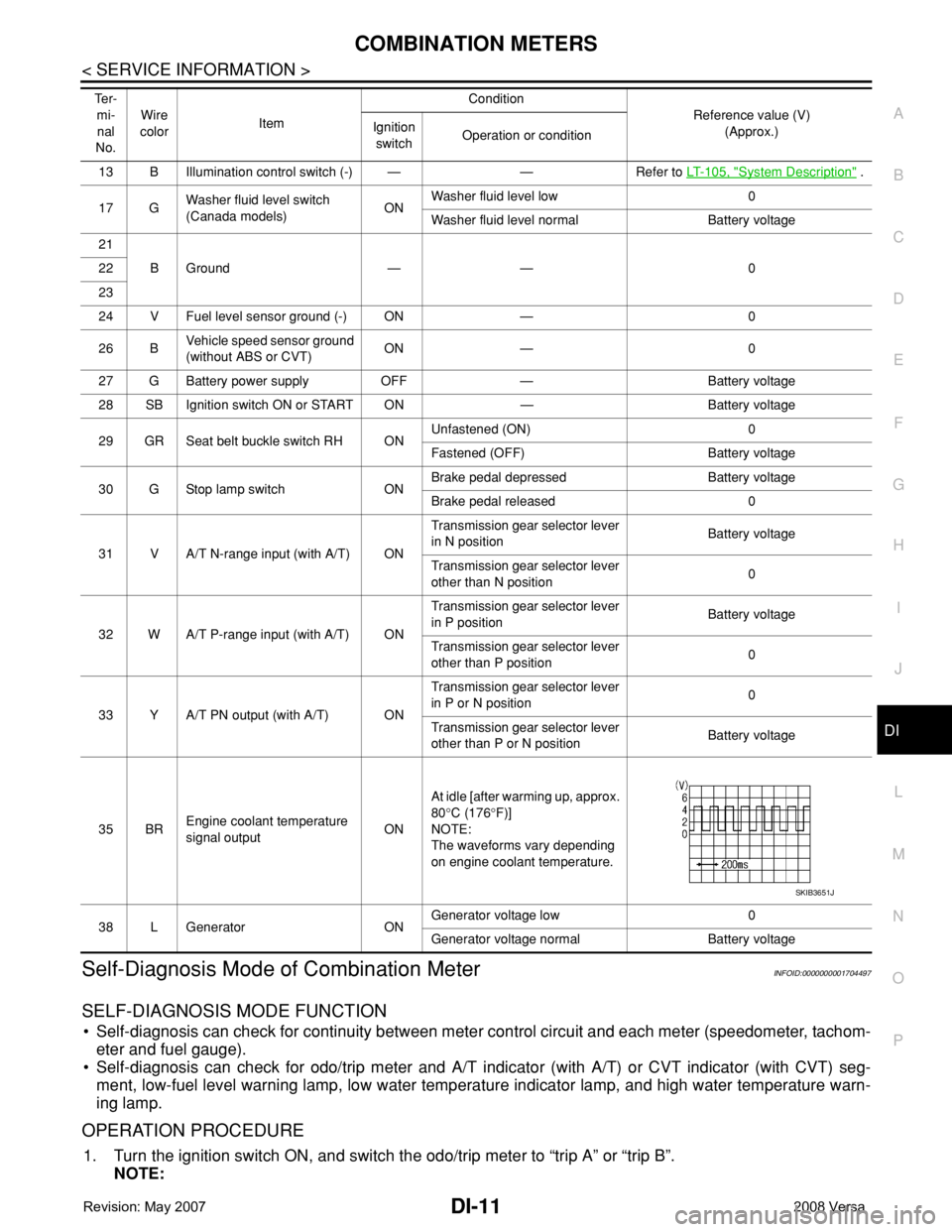
35 BREngine coolant temperature
signal outputONAt idle [after warming up, approx.
80°C (176°F)]
NOTE:
The waveforms vary depending
on engine coolant temperature.
38 L Generator ONGenerator voltage low 0
Generator voltage normal Battery voltage Te r -
mi-
nal
No.Wire
colorItemCondition
Reference value (V)
(Approx.) Ignition
switchOperation or condition
SKIB3651J
Page 1131 of 2771
ON BOARD DIAGNOSTIC (OBD) SYSTEM
EC-57
< SERVICE INFORMATION >
C
D
E
F
G
H
I
J
K
L
MA
EC
N
P O
• Sea level
• Flat road
• Ambient air temperature: 20 - 30°C (68 - 86°F)
• Diagnosis is performed as quickly as possible under normal conditions.
Under different conditions [For example: ambient air temperature other than 20 - 30°C (68 - 86°F)], diagno-
sis may also be performed.
Pattern 1:
•The engine is started at the engine coolant temperature of −10 to 35°C (14 to 95°F)
(where the voltage between the ECM terminal 38 and ground is 3.0 - 4.3V).
•The engine must be operated at idle speed until the engine coolant temperature is greater than 70°C
(158°F) (where the voltage between the ECM terminal 38 and ground is lower than 1.4V).
•The engine is started at the fuel tank temperature of warmer than 0°C (32°F) (where the voltage
between the ECM terminal 43 and ground is less than 4.1V).
Pattern 2:
• When steady-state driving is performed again even after it is interrupted, each diagnosis can be conducted.
In this case, the time required for diagnosis may be extended.
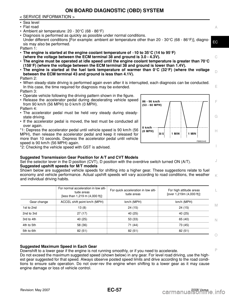
Pattern 3:
• Operate vehicle following the driving pattern shown in the figure.
• Release the accelerator pedal during decelerating vehicle speed
from 90 km/h (56 MPH) to 0 km/h (0 MPH).
Pattern 4:
• The accelerator pedal must be held very steady during steady-
state driving.
• If the accelerator pedal is moved, the test must be conducted all
over again.
*1: Depress the accelerator pedal until vehicle speed is 90 km/h (56
MPH), then release the accelerator pedal and keep it released for
more than 10 seconds. Depress the accelerator pedal until vehicle
speed is 90 km/h (56 MPH) again.
*2: Checking the vehicle speed with GST is advised.
Suggested Transmission Gear Position for A/T and CVT Models
Set the selector lever in the D position (CVT), D position with the overdrive switch turned ON (A/T).
Suggested upshift speeds for M/T models
Shown below are suggested vehicle speeds for shifting into a higher gear. These suggestions relate to fuel
economy and vehicle performance. Actual upshift speeds will vary according to road conditions, the weather
and individual driving habits.
Suggested Maximum Speed in Each Gear
Downshift to a lower gear if the engine is not running smoothly, or if you need to accelerate.
Do not exceed the maximum suggested speed (shown below) in any gear. For level road driving, use the high-
est gear suggested for that speed. Always observe posted speed limits and drive according to the road condi-
tions to ensure safe operation. Do not over-rev the engine when shifting to a lower gear as it may cause
engine damage or loss of vehicle control.
PBIB2244E
For normal acceleration in low alti-
tude areas
[less than 1,219 m (4,000 ft)]:For quick acceleration in low alti-
tude areasFor high attitude areas
[over 1,219m (4,000 ft)]:
Gear change ACCEL shift point km/h (MPH) km/h (MPH) km/h (MPH)
1st to 2nd 13 (8) 24 (15) 24 (15)
2nd to 3rd 27 (17) 40 (25) 40 (25)
3rd to 4th 40 (25) 53 (33) 65 (40)
4th to 5th 58 (36) 71 (44) 73 (45)
5th to 6th 82 (51) 82 (51) 82 (51)
Page 1161 of 2771

TROUBLE DIAGNOSIS
EC-87
< SERVICE INFORMATION >
C
D
E
F
G
H
I
J
K
L
MA
EC
N
P O
Fail-Safe ChartINFOID:0000000001702588
When the DTC listed below is detected, the ECM enters fail-safe mode and the MIL lights up.
Priority Detected items (DTC)
1 • U1000 U1001 CAN communication line
• U1010 CAN communication
• P0101 P0102 P0103 Mass air flow sensor
• P0112 P0113 P0127 Intake air temperature sensor
• P0117 P0118 P0125 Engine coolant temperature sensor
• P0122 P0123 P0222 P0223 P1225 P1226 P2135 Throttle position sensor
• P0128 Thermostat function
• P0181 P0182 P0183 Fuel tank temperature sensor
• P0327 P0328 Knock sensor
• P0335 Crankshaft position sensor (POS)
• P0340 Camshaft position sensor (PHASE)
• P0460 P0461 P0462 P0463 Fuel level sensor
• P0500 Vehicle speed sensor
• P0605 ECM
• P0643 Sensor power supply
• P0705 P0850 Park/neutral position (PNP) switch
• P1610 - P1615 NATS
• P2122 P2123 P2127 P2128 P2138 Accelerator pedal position sensor
2 • P0031 P0032 Air fuel ratio (A/F) sensor 1 heater
• P0037 P0038 Heated oxygen sensor 2 heater
• P0075 Intake valve timing control solenoid valve
• P0130 P0131 P0132 P0133 P2A00 Air fuel ratio (A/F) sensor 1
• P0137 P0138 P0139 Heated oxygen sensor 2
• P0441 EVAP control system purge flow monitoring
• P0443 P0444 P0445 EVAP canister purge volume control solenoid valve
• P0447 P0448 EVAP canister vent control valve
• P0451 P0452 P0453 EVAP control system pressure sensor
• P1217 Engine over temperature (OVERHEAT)
• P1805 Brake switch
• P2100 P2103 Throttle control motor relay
• P2101 Electric throttle control function
• P2118 Throttle control motor
3 • P0011 Intake valve timing control
• P0171 P0172 Fuel injection system function
• P0300 - P0304 Misfire
• P0420 Three way catalyst function
• P0442 P0456 EVAP control system (SMALL LEAK, VERY SMALL LEAK)
• P0455 EVAP control system (GROSS LEAK)
• P0506 P0507 Idle speed control system
• P0710 P0715 P0720 P0725 P0731 P0732 P0733 P0734 P0740 P0744 P0745 P0746 P0750 P0755 P0776 P0778
P0840 P0845 P1705 P1740 P1760 P1777 P1778 A/T or CVT related sensors, solenoid valves and switches
• P1148 Closed loop control
• P1421 Cold start control
• P1564 ASCD steering switch
• P1572 ASCD brake switch
• P1574 ASCD vehicle speed sensor
• P1715 Turbine revolution sensor (A/T), Primary speed sensor (CVT)
• P2119 Electric throttle control actuator
DTC No. Detected items Engine operating condition in fail-safe mode
P0102
P0103Mass air flow sensor circuit Engine speed will not rise more than 2,400 rpm due to the fuel cut.
Page 1166 of 2771

EC-92
< SERVICE INFORMATION >
TROUBLE DIAGNOSIS
1 - 6: The numbers refer to the order of inspection.Cooling Radiator/Hose/Radiator filler cap
55555 55 45CO-11
Thermostat 5CO-17
Water pumpCO-16
Water galleryCO-7
Cooling fan
5CO-14
Coolant level (Low)/Contaminat-
ed coolantCO-8
NVIS (NISSAN Vehicle Immobilizer System-
NATS)11BL-210
SYMPTOM
Reference
page
HARD/NO START/RESTART (EXCP. HA)
ENGINE STALL
HESITATION/SURGING/FLAT SPOT
SPARK KNOCK/DETONATION
LACK OF POWER/POOR ACCELERATION
HIGH IDLE/LOW IDLE
ROUGH IDLE/HUNTING
IDLING VIBRATION
SLOW/NO RETURN TO IDLE
OVERHEATS/WATER TEMPERATURE HIGH
EXCESSIVE FUEL CONSUMPTION
EXCESSIVE OIL CONSUMPTION
BATTERY DEAD (UNDER CHARGE)
Warranty symptom code AA AB AC AD AE AF AG AH AJ AK AL AM HA
Page 1184 of 2771

EC-110
< SERVICE INFORMATION >
TROUBLE DIAGNOSIS
ItemDIAGNOSTIC TEST MODE
WORK
SUP-
PORTSELF-DIAGNOSTIC
RESULTS
DATA
MONI-
TORDATA
MONI-
TOR
(SPEC)ACTIVE
TESTDTC & SRT
CONFIRMATION
DTC*
1 FREEZE
FRAME
DATA*
2
SRT
STATUSDTC
WORK
SUP-
PORT
ENGINE CONTROL COMPONENT PARTS
INPUT
Crankshaft position sensor (POS)××××
Camshaft position sensor (PHASE)××××
Mass air flow sensor×××
Engine coolant temperature sensor×××××
Air fuel ratio (A/F) sensor 1×××××
Heated oxygen sensor 2×××××
Wheel sensor××××
Accelerator pedal position sensor×××
Throttle position sensor× ×××
Fuel tank temperature sensor××××
EVAP control system pressure sen-
sor×××
Intake air temperature sensor××××
Knock sensor×
Refrigerant pressure sensor××
Closed throttle position switch (Ac-
celerator pedal position sensor sig-
nal)××
Air conditioner switch××
Park/neutral position (PNP) switch×××
Stop lamp switch×××
Battery voltage××
Load signal ××
Fuel level sensor×××
ASCD steering switch×××
ASCD brake switch×××
ASCD clutch switch×××
EPS control unit××
Page 1344 of 2771
EC-270
< SERVICE INFORMATION >
DTC P0181 FTT SENSOR
DTC P0181 FTT SENSOR
Component DescriptionINFOID:0000000001702768
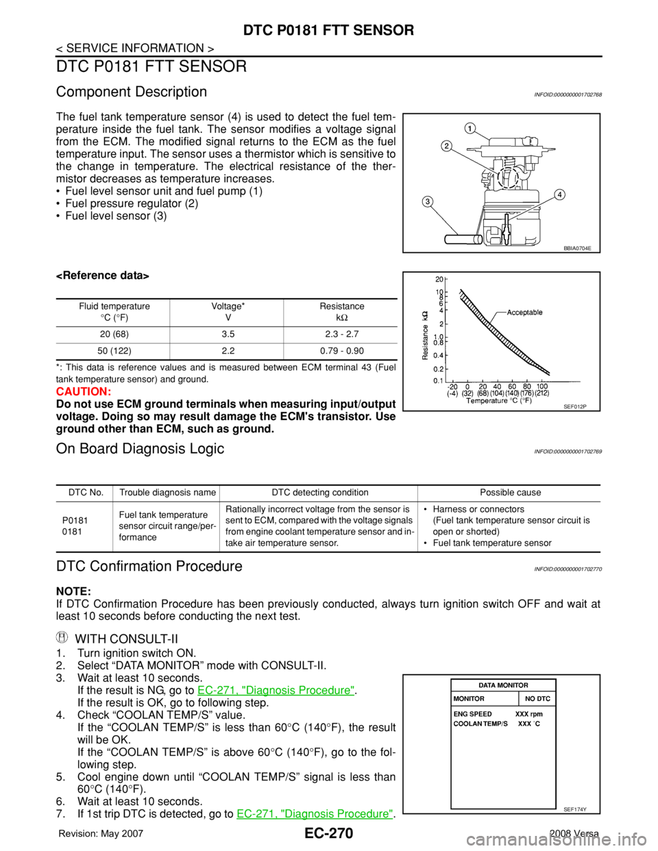
The fuel tank temperature sensor (4) is used to detect the fuel tem-
perature inside the fuel tank. The sensor modifies a voltage signal
from the ECM. The modified signal returns to the ECM as the fuel
temperature input. The sensor uses a thermistor which is sensitive to
the change in temperature. The electrical resistance of the ther-
mistor decreases as temperature increases.
• Fuel level sensor unit and fuel pump (1)
• Fuel pressure regulator (2)
• Fuel level sensor (3)
*: This data is reference values and is measured between ECM terminal 43 (Fuel
tank temperature sensor) and ground.
CAUTION:
Do not use ECM ground terminals when measuring input/output
voltage. Doing so may result damage the ECM's transistor. Use
ground other than ECM, such as ground.
On Board Diagnosis LogicINFOID:0000000001702769
DTC Confirmation ProcedureINFOID:0000000001702770
NOTE:
If DTC Confirmation Procedure has been previously conducted, always turn ignition switch OFF and wait at
least 10 seconds before conducting the next test.
WITH CONSULT-II
1. Turn ignition switch ON.
2. Select “DATA MONITOR” mode with CONSULT-II.
3. Wait at least 10 seconds.
If the result is NG, go to EC-271, "
Diagnosis Procedure".
If the result is OK, go to following step.
4. Check “COOLAN TEMP/S” value.
If the “COOLAN TEMP/S” is less than 60°C (140°F), the result
will be OK.
If the “COOLAN TEMP/S” is above 60°C (140°F), go to the fol-
lowing step.
5. Cool engine down until “COOLAN TEMP/S” signal is less than
60°C (140°F).
6. Wait at least 10 seconds.
7. If 1st trip DTC is detected, go to EC-271, "
Diagnosis Procedure".
BBIA0704E
Fluid temperature
°C (°F)Voltage*
VResistance
kΩ
20 (68) 3.5 2.3 - 2.7
50 (122) 2.2 0.79 - 0.90
SEF012P
DTC No. Trouble diagnosis name DTC detecting condition Possible cause
P0181
0181Fuel tank temperature
sensor circuit range/per-
formanceRationally incorrect voltage from the sensor is
sent to ECM, compared with the voltage signals
from engine coolant temperature sensor and in-
take air temperature sensor.• Harness or connectors
(Fuel tank temperature sensor circuit is
open or shorted)
• Fuel tank temperature sensor
SEF174Y
Page 1487 of 2771
DTC P1217 ENGINE OVER TEMPERATURE
EC-413
< SERVICE INFORMATION >
C
D
E
F
G
H
I
J
K
L
MA
EC
N
P O Cooling Fan Relay Operation
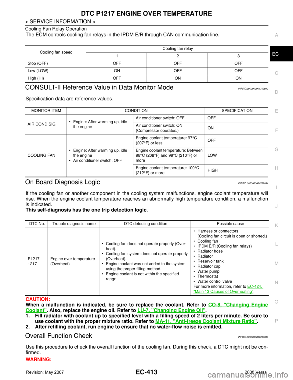
The ECM controls cooling fan relays in the IPDM E/R through CAN communication line.
CONSULT-II Reference Value in Data Monitor ModeINFOID:0000000001702930
Specification data are reference values.
On Board Diagnosis LogicINFOID:0000000001702931
If the cooling fan or another component in the cooling system malfunctions, engine coolant temperature will
rise. When the engine coolant temperature reaches an abnormally high temperature condition, a malfunction
is indicated.
This self-diagnosis has the one trip detection logic.
CAUTION:
When a malfunction is indicated, be sure to replace the coolant. Refer to CO-8, "
Changing Engine
Coolant". Also, replace the engine oil. Refer to LU-7, "Changing Engine Oil".
1. Fill radiator with coolant up to specified level with a filling speed of 2 liters per minute. Be sure to
use coolant with the proper mixture ratio. Refer to MA-11, "
Anti-freeze Coolant Mixture Ratio".
2. After refilling coolant, run engine to ensure that no water-flow noise is emitted.
Overall Function CheckINFOID:0000000001702932
Use this procedure to check the overall function of the cooling fan. During this check, a DTC might not be con-
firmed.
WARNING:
Cooling fan speedCooling fan relay
123
Stop (OFF) OFF OFF OFF
Low (LOW) ON OFF OFF
High (HI) OFF ON ON
MONITOR ITEM CONDITION SPECIFICATION
AIR COND SIG• Engine: After warming up, idle
the engineAir conditioner switch: OFF OFF
Air conditioner switch: ON
(Compressor operates.)ON
COOLING FAN• Engine: After warming up, idle
the engine
• Air conditioner switch: OFFEngine coolant temperature: 97°C
(207°F) or lessOFF
Engine coolant temperature: Between
98°C (208°F) and 99°C (210°F) or
moreLOW
Engine coolant temperature: 100°C
(212°F) or moreHIGH
DTC No. Trouble diagnosis name DTC detecting condition Possible cause
P1217
1217Engine over temperature
(Overheat)• Cooling fan does not operate properly (Over-
heat).
• Cooling fan system does not operate properly
(Overheat).
• Engine coolant was not added to the system
using the proper filling method.
• Engine coolant is not within the specified
range.• Harness or connectors
(Cooling fan circuit is open or shorted.)
• Cooling fan
• IPDM E/R (Cooling fan relays)
•Radiator hose
•Radiator
• Reservoir tank
•Radiator cap
• Water pump
•Thermostat
• Water control valve
For more information, refer to EC-424,
"Main 13 Causes of Overheating".