coolant reservoir NISSAN LATIO 2008 Service Repair Manual
[x] Cancel search | Manufacturer: NISSAN, Model Year: 2008, Model line: LATIO, Model: NISSAN LATIO 2008Pages: 2771, PDF Size: 60.61 MB
Page 822 of 2771

OVERHEATING CAUSE ANALYSIS
CO-5
< SERVICE INFORMATION >
C
D
E
F
G
H
I
J
K
L
MA
CO
N
P O
OVERHEATING CAUSE ANALYSIS
Troubleshooting ChartINFOID:0000000001702527
Symptom Check items
Cooling sys-
tem parts
malfunctionPoor heat transferWater pump malfunction Worn or loose drive belt
— Thermostat stuck closed Thermostat
Damaged finsDust contamination or pa-
per clogging
Physical damage
Clogged radiator cooling
tubeExcess foreign material
(rust, dirt, sand, etc.)
Reduced air flowCooling fan does not oper-
ate
Fan assembly— High resistance to fan rota-
tion
Damaged fan blades
Damaged radiator shroud — —
Improper engine coolant
mixture ratio—
—
Engine coolant viscosity—
Poor engine coolant quality — —
Insufficient engine coolantEngine coolant leaksCooling hoseLoose clamp
Cracked hose
Water pump Poor sealing
Radiator capLoose
Poor sealing
RadiatorO-ring for damage, deterio-
ration or improper fitting
Cracked radiator tank
Cracked radiator core
Reservoir tank Cracked reservoir tank
Overflowing reservoir tankExhaust gas leaks into cool-
ing systemCylinder head deterioration
Cylinder head gasket deteri-
oration
Page 825 of 2771

CO-8
< SERVICE INFORMATION >
ENGINE COOLANT
ENGINE COOLANT
InspectionINFOID:0000000001702529
LEVEL CHECK
• Check if the reservoir tank engine coolant level is within the “MIN”
to “MAX” range when engine is cool.
• Adjust the engine coolant level as necessary.
CHECKING COOLING SYSTEM FOR LEAKS
To check for leaks, apply pressure to the cooling system using Tool.
WARNING:
Never remove the radiator cap when the engine is hot. Serious
burns could occur from high pressure coolant escaping from
the radiator.
CAUTION:
Higher pressure than specified may cause radiator damage.
Changing Engine CoolantINFOID:0000000001702530
WARNING:
• To avoid being scalded, do not change engine coolant when engine is hot.
• Wrap a thick cloth around radiator cap and carefully remove the cap. First, turn the cap a quarter of a
turn to release built-up pressure. Then turn the cap all the way.
• Be careful not to allow engine coolant to contact drive belt.
DRAINING ENGINE COOLANT
1. Open radiator drain plug (1) at the bottom of radiator, and then
remove radiator cap.
• Front
When drain all of engine coolant in the system, open water
drain plug on cylinder block. Refer to EM-76
.
CAUTION:
• Perform this step when engine is cold.
• Do not spill engine coolant on drive belt.
2. Remove reservoir tank as necessary, and drain engine coolant and clean reservoir tank before installing.
Refer to CO-11
.
3. Check drained engine coolant for contaminants such as rust, corrosion or discoloration.
If contaminated, flush the engine cooling system. Follow the "FLUSHING COOLING SYSTEM" proce-
dure.
REFILLING ENGINE COOLANT
SMA412B
Tool number : EG17650301 (J-33984-A)
Testing pressure
: 157 kPa (1.6 kg/cm
2, 23 psi)
WBIA0568E
PBIC3799E
Page 826 of 2771

ENGINE COOLANT
CO-9
< SERVICE INFORMATION >
C
D
E
F
G
H
I
J
K
L
MA
CO
N
P O
1. Install reservoir tank if removed. Refer to CO-11.
2. Install radiator drain plug.
•If water drain plug on cylinder block is removed, close and tighten it. Refer to EM-76
.
CAUTION:
Be sure to clean radiator drain plug and install with new O-ring. Refer to CO-11, "
Component".
3. Make sure that each hose clamp has been firmly tightened.
4. Remove air duct assembly. Refer to EM-16
.
5. Disconnect heater hose (1) at position ( ) as shown.
• Front
• Reposition heater hose as high as possible.
6. Fill radiator and reservoir tank to specified level.
•Pour engine coolant through engine coolant filler neck
slowly of less than 2 (2 1/8 US qt, 1-3/4 lmp qt) a minute
to allow air in system to escape.
•Use NISSAN Genuine Engine Coolant or equivalent mixed
with water (distilled or demineralized). Fill cooling system
to specification. Refer to MA-10
.
• When engine coolant overflows disconnected heater hose,
connect heater hose, and continue filling the engine coolant, if
heater hose is disconnected.
7. Install radiator cap.
8. Install air duct assembly. Refer to EM-16
.
9. Warm up until opening thermostat. Standard for warming-up time is approximately 10 minutes at 3,000
rpm.
• Make sure thermostat opening condition by touching radiator hose (lower) to see a flow of warm water.
CAUTION:
Watch water temperature gauge so as not to overheat the engine.
10. Stop engine and cool down to less than approximately 50°C (122°F).
• Cool down using fan to reduce the time.
• If necessary, refill radiator up to filler neck with engine coolant.
11. Refill reservoir tank to “MAX” level line with engine coolant.
12. Repeat steps 6 through 11 two or more times with radiator cap installed until engine coolant level no
longer drops.
13. Check cooling system for leaks with engine running.
14. Warm up engine, and check for sound of engine coolant flow while running engine from idle up to 3,000
rpm with heater temperature controller set at several position between “COOL” and “WARM”.
• Sound may be noticeable at heater unit.
15. Repeat step 14 three times.
16. If sound is heard, bleed air from cooling system by repeating steps 6 through 11 until engine coolant level
no longer drops.
FLUSHING COOLING SYSTEM
1. Install reservoir tank if removed. Refer to CO-11.
2. Install radiator drain plug.
•If water drain plug on cylinder block is removed, close and tighten it. Refer to EM-76
.
CAUTION:
Be sure to clean radiator drain plug and install with new O-ring. Refer to CO-11, "
Component".
PBIC3802E
SMA182B
Page 827 of 2771

CO-10
< SERVICE INFORMATION >
ENGINE COOLANT
3. Fill radiator and reservoir tank with water and reinstall radiator cap.
4. Run engine and warm it up to normal operating temperature.
5. Rev engine two or three times under no-load.
6. Stop engine and wait until it cools down.
7. Drain water from the cooling system. Refer to CO-8, "
Changing Engine Coolant".
8. Repeat steps 1 through 7 until clear water begins to drain from radiator.
Page 829 of 2771

CO-12
< SERVICE INFORMATION >
RADIATOR
Do not remove radiator cap when the engine is hot. Serious burns could occur from high-pressure
engine coolant escaping from radiator. Wrap a thick cloth around the cap. Slowly turn it a quarter of a
turn to release built-up pressure. Carefully remove radiator cap by turning it all the way.
REMOVAL
1. Drain engine coolant from radiator. Refer to CO-8, "Changing Engine Coolant".
CAUTION:
• Perform this step when engine is cold.
• Do not spill engine coolant on drive belt.
2. Remove air duct (inlet). Refer to EM-16
.
3. Remove reservoir tank as follows:
a. Disconnect reservoir tank hose.
b. Release the tab (A) in the direction shown by the arrow ( ).
c. Lift up while removing the reservoir tank hose, and remove it.
4. Disconnect harness connector from fan motors, and move harness to aside.
5. Disconnect CVT or A/T fluid cooler hoses if equipped.
• Install plug to avoid leakage of CVT or A/T fluid if equipped.
6. Remove radiator hoses (upper and lower).
7. Remove radiator core support cover. Refer toBL-19
.
8. Remove radiator core support (upper) bolts, bolts of stationary
part on the radiator core support side and clip. Lift radiator from
radiator (upper) mount part of radiator core support (upper) (2).
9. Move radiator assembly (1) to the rearward direction of vehicle,
and then lift it upward to remove.
CAUTION:
Do not damage or scratch A/C condenser if equipped and
radiator core when removing.
INSTALLATION
Installation is the reverse order of removal.
CAUTION:
Do not damage or scratch A/C condenser if equipped and radiator core when removing.
INSPECTION AFTER INSTALLATION
• Check for leaks of engine coolant. Refer to CO-8, "Inspection".
• Start and warm up engine. Visually check if there is no leaks of engine coolant and CVT or A/T fluid if
equipped. Refer to CVT-13
or AT- 1 5.
PBIC3800E
PBIC3805E
Page 832 of 2771

COOLING FAN
CO-15
< SERVICE INFORMATION >
C
D
E
F
G
H
I
J
K
L
MA
CO
N
P O
Removal and InstallationINFOID:0000000001702537
REMOVAL
1. Drain engine coolant from radiator. Refer to CO-8, "Changing Engine Coolant".
CAUTION:
• Perform this step when engine is cold.
• Do not spill engine coolant on drive belt.
2. Remove air duct (inlet). Refer to EM-16, "
Component".
3. Remove reservoir tank. Refer to CO-11, "
Component".
4. Disconnect radiator hose (upper) at radiator side. Refer to CO-11, "
Component".
5. Disconnect harness connectors from fan motor, and move harness to aside.
6. Remove cooling fan assembly.
CAUTION:
Be careful not to damage or scratch the radiator core.
INSTALLATION
Installation is the reverse order of removal.
• Cooling fans are controlled by ECM. For details, refer to EC-412
.
CAUTION:
Be careful not to damage or scratch the radiator core.
DISASSEMBLY AND ASSEMBLYINFOID:0000000001702538
Disassembly
1. Remove cooling fan from fan motor.
2. Remove fan motor from fan shroud.
Inspection After Disassembly
Inspect cooling fan for crack or unusual bend.
• If anything is found, replace cooling fan.
Assembly
Assembly is the reverse order of disassembly.
Page 839 of 2771

SERVICE DATA AND SPECIFICATIONS (SDS)
Standard and LimitINFOID:0000000001702545
CAPACITY
Unit: (US qt, lmp qt)
THERMOSTAT
WATER CO")
CO-22
< SERVICE INFORMATION >
SERVICE DATA AND SPECIFICATIONS (SDS)
SERVICE DATA AND SPECIFICATIONS (SDS)
Standard and LimitINFOID:0000000001702545
CAPACITY
Unit: (US qt, lmp qt)
THERMOSTAT
WATER CONTROL VALVE
RADIATOR
Unit: kPa (bar, kg/cm2, psi)
Engine coolant capacity (with reservoir tank at “MAX” level) Approx. 6.8 (7 1/4, 6.0)
Valve opening temperature 80.5 - 83.5°C (177 - 182°F)
Maximum valve lift 8 mm/ 95°C (0.315 in/ 203°F)
Valve closing temperature 77°C (171°F)
Valve opening temperature 93.5 - 96.5°C (200 - 206°F)
Maximum valve lift 8 mm/ 108°C (0.315 in/ 226°F)
Valve closing temperature 90°C (194°F)
Cap relief pressureStandard 78 - 98 (0.78 - 0.98, 0.8 - 1.0, 11- 14)
Limit 59 (0.59, 0.6, 9)
Leakage test pressure 157 (1.57, 1.6, 23)
Page 1487 of 2771

DTC P1217 ENGINE OVER TEMPERATURE
EC-413
< SERVICE INFORMATION >
C
D
E
F
G
H
I
J
K
L
MA
EC
N
P O Cooling Fan Relay Operation
The ECM controls cooling fan relays in the IPDM E/R through CAN communication line.
CONSULT-II Reference Value in Data Monitor ModeINFOID:0000000001702930
Specification data are reference values.
On Board Diagnosis LogicINFOID:0000000001702931
If the cooling fan or another component in the cooling system malfunctions, engine coolant temperature will
rise. When the engine coolant temperature reaches an abnormally high temperature condition, a malfunction
is indicated.
This self-diagnosis has the one trip detection logic.
CAUTION:
When a malfunction is indicated, be sure to replace the coolant. Refer to CO-8, "
Changing Engine
Coolant". Also, replace the engine oil. Refer to LU-7, "Changing Engine Oil".
1. Fill radiator with coolant up to specified level with a filling speed of 2 liters per minute. Be sure to
use coolant with the proper mixture ratio. Refer to MA-11, "
Anti-freeze Coolant Mixture Ratio".
2. After refilling coolant, run engine to ensure that no water-flow noise is emitted.
Overall Function CheckINFOID:0000000001702932
Use this procedure to check the overall function of the cooling fan. During this check, a DTC might not be con-
firmed.
WARNING:
Cooling fan speedCooling fan relay
123
Stop (OFF) OFF OFF OFF
Low (LOW) ON OFF OFF
High (HI) OFF ON ON
MONITOR ITEM CONDITION SPECIFICATION
AIR COND SIG• Engine: After warming up, idle
the engineAir conditioner switch: OFF OFF
Air conditioner switch: ON
(Compressor operates.)ON
COOLING FAN• Engine: After warming up, idle
the engine
• Air conditioner switch: OFFEngine coolant temperature: 97°C
(207°F) or lessOFF
Engine coolant temperature: Between
98°C (208°F) and 99°C (210°F) or
moreLOW
Engine coolant temperature: 100°C
(212°F) or moreHIGH
DTC No. Trouble diagnosis name DTC detecting condition Possible cause
P1217
1217Engine over temperature
(Overheat)• Cooling fan does not operate properly (Over-
heat).
• Cooling fan system does not operate properly
(Overheat).
• Engine coolant was not added to the system
using the proper filling method.
• Engine coolant is not within the specified
range.• Harness or connectors
(Cooling fan circuit is open or shorted.)
• Cooling fan
• IPDM E/R (Cooling fan relays)
•Radiator hose
•Radiator
• Reservoir tank
•Radiator cap
• Water pump
•Thermostat
• Water control valve
For more information, refer to EC-424,
"Main 13 Causes of Overheating".
Page 1488 of 2771

EC-414
< SERVICE INFORMATION >
DTC P1217 ENGINE OVER TEMPERATURE
Never remove the radiator cap when the engine is hot. Serious burns could be caused by high pres-
sure fluid escaping from the reservoir tank or the radiator.
Wrap a thick cloth around cap. Carefully remove the cap by turning it a quarter turn to allow built-up
pressure to escape. Then turn the cap all the way off.
WITH CONSULT-II
1. Check the coolant level in the reservoir tank and radiator.
Allow engine to cool before checking coolant level.
If the coolant level in the reservoir tank and/or radiator is below
the proper range, skip the following steps and go to EC-417,
"Diagnosis Procedure" or EC-417, "Diagnosis Procedure".
2. Confirm whether customer filled the coolant or not. If customer
filled the coolant, skip the following steps and go to EC-417,
"Diagnosis Procedure" or EC-417, "Diagnosis Procedure".
3. Turn ignition switch ON.
4. Perform “COOLING FAN” in “ACTIVE TEST” mode with CON-
SULT-II.
5. If the results are NG, go to EC-417, "
Diagnosis Procedure" or
EC-417, "
Diagnosis Procedure".
WITH GST
Models with A/C
1. Check the coolant level in the reservoir tank and radiator.
Allow engine to cool before checking coolant level.
If the coolant level in the reservoir tank and/or radiator is below
the proper range, skip the following steps and go to EC-417,
"Diagnosis Procedure".
2. Confirm whether customer filled the coolant or not. If customer
filled the coolant, skip the following steps and go to EC-417,
"Diagnosis Procedure".
3. Start engine.
CAUTION:
Be careful not to overheat engine.
4. Set temperature control switch to full cold position.
5. Turn air conditioner switch ON.
6. Turn blower fan switch ON.
7. Run engine at idle for a few minutes with air conditioner operating.
CAUTION:
Be careful not to overheat engine.
SEF621W
SEF646X
SEF621W
Page 1489 of 2771
DTC P1217 ENGINE OVER TEMPERATURE
EC-415
< SERVICE INFORMATION >
C
D
E
F
G
H
I
J
K
L
MA
EC
N
P O
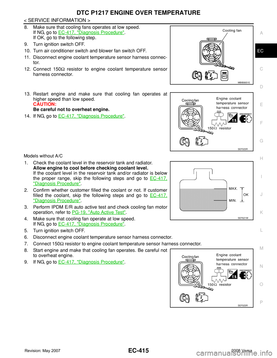
8. Make sure that cooling fans operates at low speed.
If NG, go to EC-417, "
Diagnosis Procedure".
If OK, go to the following step.
9. Turn ignition switch OFF.
10. Turn air conditioner switch and blower fan switch OFF.
11. Disconnect engine coolant temperature sensor harness connec-
tor.
12. Connect 150Ω resistor to engine coolant temperature sensor
harness connector.
13. Restart engine and make sure that cooling fan operates at
higher speed than low speed.
CAUTION:
Be careful not to overheat engine.
14. If NG, go to EC-417, "
Diagnosis Procedure".
Models without A/C
1. Check the coolant level in the reservoir tank and radiator.
Allow engine to cool before checking coolant level.
If the coolant level in the reservoir tank and/or radiator is below
the proper range, skip the following steps and go to EC-417,
"Diagnosis Procedure".
2. Confirm whether customer filled the coolant or not. If customer
filled the coolant, skip the following steps and go to EC-417,
"Diagnosis Procedure".
3. Perform IPDM E/R auto active test and check cooling fan motor
operation, refer to PG-19, "
Auto Active Test".
4. Make sure that cooling fan operate at low speed.
If NG, go to EC-417, "
Diagnosis Procedure".
5. Turn ignition switch OFF.
6. Disconnect engine coolant temperature sensor harness connector.
7. Connect 150Ω resistor to engine coolant temperature sensor harness connector.
8. Start engine and make that cooling fan operates. Be careful not
to overheat engine.
9. If NG, go to EC-417, "
Diagnosis Procedure".
MBIB0651E
SEF023R
SEF621W
SEF023R